
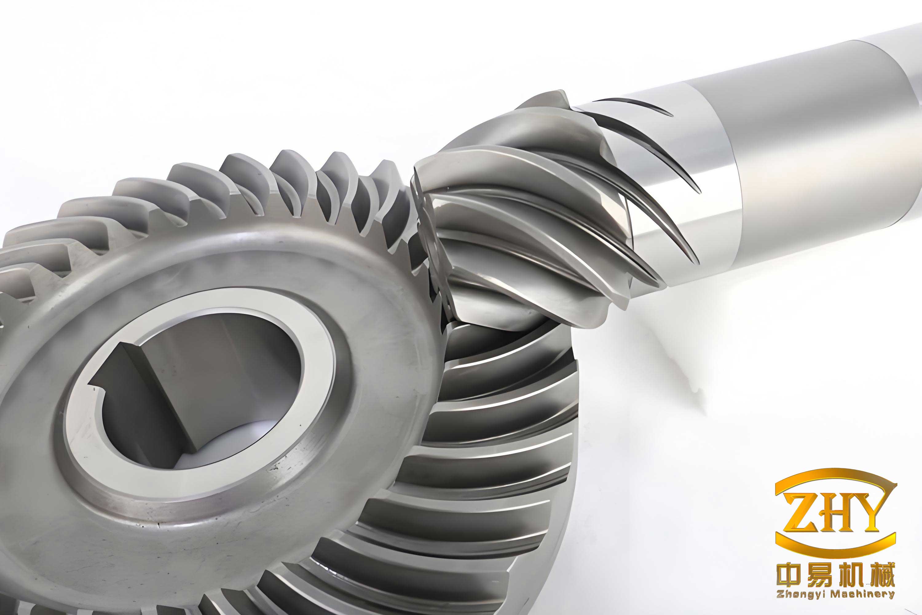
In this article, I will delve into the intricate relationship between misalignment and tooth contact patterns in spiral bevel gears, a critical component in power transmission systems for aerospace, automotive, and machinery applications. The performance of spiral bevel gears heavily relies on the quality of their meshing, characterized by the tooth contact pattern and transmission error. However, in real-world operating conditions, various factors such as assembly errors, deformations of housings, bearings, and shafts, manufacturing inaccuracies, and thermal effects introduce misalignments that shift the contact pattern away from its ideal position. This shift can degrade gear strength, increase vibration, and reduce overall efficiency. Therefore, I aim to present a comprehensive methodology for identifying equivalent misalignments based on observed contact pattern deviations and redesigning the pinion tooth surface to restore optimal meshing under actual conditions. The focus will be on the spiral bevel gear, a gear type known for its smooth operation and high load capacity, and I will emphasize its geometry and behavior throughout the discussion.
To set the stage, I will first explain the fundamental concepts of misalignment in spiral bevel gear assemblies. According to standard specifications, the primary misalignment factors include pinion axial displacement \(\Delta P\), gear axial displacement \(\Delta G\), offset \(\Delta E\) (deviation in shaft distance), and shaft angle error \(\Delta \Sigma\). These misalignments alter the relative positioning of the pinion and gear, leading to changes in the tooth contact pattern. In my analysis, I consider a spiral bevel gear pair where the pinion and gear are represented in their respective coordinate systems. Let me define the coordinate systems: \(S_1\) and \(S_2\) are attached to the pinion and gear, respectively, \(S_h\) is a fixed reference frame, and an auxiliary frame \(S_c\) helps describe misalignments. The transformation matrices between these frames incorporate the misalignment parameters and rotation angles \(\phi_1\) and \(\phi_2\) for the pinion and gear.
The position vectors and unit normals of the pinion and gear tooth surfaces, denoted as \(\mathbf{r}^{(1)}\), \(\mathbf{n}^{(1)}\) for the pinion and \(\mathbf{r}^{(2)}\), \(\mathbf{n}^{(2)}\) for the gear, are expressed in the fixed frame \(S_h\) using homogeneous transformation matrices. For the pinion:
$$
\mathbf{r}_h^{(1)} = \mathbf{M}_{h1}(\phi_1, \Delta P) \mathbf{r}_1^{(1)}(\theta_p, \phi_p), \quad \mathbf{n}_h^{(1)} = \mathbf{M}_{h1}(\phi_1, \Delta P) \mathbf{n}_1^{(1)}(\theta_p, \phi_p),
$$
and for the gear:
$$
\mathbf{r}_h^{(2)} = \mathbf{M}_{hc}(\Delta E, \Delta \Sigma) \mathbf{M}_{c2}(\phi_2, \Delta G) \mathbf{r}_2^{(2)}(\theta_g, \phi_g), \quad \mathbf{n}_h^{(2)} = \mathbf{M}_{hc}(\Delta E, \Delta \Sigma) \mathbf{M}_{c2}(\phi_2, \Delta G) \mathbf{n}_2^{(2)}(\theta_g, \phi_g),
$$
where \(\theta_i, \phi_i\) (with \(i = p, g\)) are the surface parameters. The transformation matrices are defined as follows:
$$
\mathbf{M}_{h1} = \begin{bmatrix}
1 & 0 & 0 & \Delta P \\
0 & \cos \phi_1 & -\sin \phi_1 & 0 \\
0 & \sin \phi_1 & \cos \phi_1 & 0 \\
0 & 0 & 0 & 1
\end{bmatrix}, \quad \mathbf{M}_{c2} = \begin{bmatrix}
1 & 0 & 0 & \Delta G \\
0 & -\cos \phi_2 & -\sin \phi_2 & 0 \\
0 & \sin \phi_2 & -\cos \phi_2 & 0 \\
0 & 0 & 0 & 1
\end{bmatrix},
$$
and
$$
\mathbf{M}_{hc} = \begin{bmatrix}
\cos(\Sigma + \Delta \Sigma) & 0 & \sin(\Sigma + \Delta \Sigma) & 0 \\
0 & 1 & 0 & \Delta E \\
-\sin(\Sigma + \Delta \Sigma) & 0 & \cos(\Sigma + \Delta \Sigma) & 0 \\
0 & 0 & 0 & 1
\end{bmatrix},
$$
with \(\Sigma\) being the nominal shaft angle. The tooth contact analysis (TCA) equations require continuous tangency between the pinion and gear surfaces in \(S_h\):
$$
\mathbf{r}_h^{(1)} = \mathbf{r}_h^{(2)}, \quad \mathbf{n}_h^{(1)} = \mathbf{n}_h^{(2)}.
$$
Given the misalignment vector \(\mathbf{D} = [\Delta P, \Delta G, \Delta E, \Delta \Sigma]^T\), and treating \(\phi_1\) as the input, I can solve these equations to obtain contact points along the tooth surface. By varying \(\phi_1\) in steps, the contact path is determined. At each contact point, the relative curvature of the surfaces is computed, and based on an elastic deformation limit (e.g., 0.00635 mm), the contact ellipse is calculated. The tooth contact pattern is then formed by a series of these ellipses. This geometric contact analysis model for spiral bevel gears allows me to simulate how misalignments affect the meshing behavior.
Now, I will address a key insight: the multiplicity of solutions in misalignment identification. Different combinations of misalignments can produce identical tooth contact patterns. This occurs because the meshing state of a spiral bevel gear pair depends on the relative position vector between any two points on the pinion and gear surfaces in the fixed frame. If two different misalignment sets yield the same relative vector—termed the “spatial equivalent vector”—the contact patterns will be indistinguishable. This equivalence simplifies the misalignment identification problem: instead of seeking the true misalignment values, which may be difficult to determine due to complex structural deformations and errors, I can aim to find an equivalent misalignment set that matches the observed contact pattern. This approach reduces the complexity, as I no longer need to analyze the root causes of pattern shifts from mechanical or thermal perspectives.
To identify the equivalent misalignment, I must first quantify the tooth contact pattern from physical resources like impression films or photos. I extract digital features of the pattern, including the center coordinates \((x, y)\), area \(s\), and orientation angle \(\alpha\). The center represents the overall position, the area relates to load capacity, and the orientation angle indicates the direction of contact movement along the tooth surface. For a given misalignment vector \(\mathbf{D}\), the contact path curve \(l_d\) is obtained from TCA simulation. It is discretized into points \(\mathbf{p}_i = \mathbf{p}_i(\mathbf{D})\) with normals \(\mathbf{n}_i = \mathbf{n}_i(\mathbf{D})\) for \(i = 1, \ldots, m\). The actual contact path curve \(l_t\) from the observed pattern is also discretized as \(\mathbf{p}_i^*\). The deviation between \(l_d\) and \(l_t\) is computed by solving for the perpendicular distance \(h_i\) from \(\mathbf{p}_i^*\) to \(l_d\), expressed as:
$$
\mathbf{p}_i^* = \mathbf{p}_i + \mathbf{n}_i h_i.
$$
I then formulate an optimization problem to minimize the sum of squared deviations between the two curves. The objective function is:
$$
\min f(\mathbf{D}) = C_p \mathbf{h}_p(\mathbf{D})^T \mathbf{h}_p(\mathbf{D}) + C_g \mathbf{h}_g(\mathbf{D})^T \mathbf{h}_g(\mathbf{D}),
$$
where \(\mathbf{h}_p\) and \(\mathbf{h}_g\) are deviation vectors for the pinion and gear contact paths, respectively, and \(C_p\) and \(C_g\) are weighting factors (both set to 0.5 in my example). Due to the multiplicity of solutions, I constrain the misalignment components to reasonable ranges: displacement components between \(-1.0\) and \(+1.0\) mm, and angle components between \(-1.0^\circ\) and \(+1.0^\circ\). To handle the optimization, I fix one component (e.g., \(\Delta G\)) as a constant and treat the others as variables. This least-squares approach ensures that the identified equivalent misalignment closely matches the observed contact pattern of the spiral bevel gear.
Once the equivalent misalignment \(\mathbf{D}_e\) is identified, I proceed to redesign the pinion tooth surface to compensate for the misalignment effects. The goal is to adjust the pinion’s machine settings so that under the actual misaligned conditions, the spiral bevel gear pair maintains a favorable contact pattern and transmission error. I employ the local synthesis method, which designs the pinion surface based on predefined second-order contact parameters at a reference point. However, I modify the method to account for misalignments by incorporating the transformation matrices that include \(\mathbf{D}_e\). Specifically, the position vector, unit normal, and principal directions of the gear surface at the reference point are transformed from coordinate system \(S_2\) to \(S_h\) using \(\mathbf{M}_{hc}\) and \(\mathbf{M}_{c2}\), and then to \(S_1\) using the inverse transformation \(\mathbf{M}_{1h}\), where:
$$
\mathbf{M}_{1h} = \begin{bmatrix}
1 & 0 & 0 & -\Delta P \\
0 & \cos \phi_1 & \sin \phi_1 & 0 \\
0 & -\sin \phi_1 & \cos \phi_1 & 0 \\
0 & 0 & 0 & 1
\end{bmatrix}.
$$
This ensures that the local contact conditions, such as the derivative of the gear ratio function \(m_{21}’\), the tangent direction of the contact path \(\eta_2\), and the semi-major axis length \(a\) of the contact ellipse, are computed with misalignment considered. Based on these parameters, I recalculate the pinion machine settings, including tool radius, cutter profile angle, radial distance, and modified roll coefficients, to generate a new pinion tooth surface that aligns with the desired meshing performance for the spiral bevel gear.
To demonstrate the methodology, I present a numerical example involving a spiral bevel gear pair. The gear is generated by a face-milling method, and the pinion is produced by a modified roll method. The basic design parameters are summarized in the table below.
| Gear | Number of Teeth | Module (mm) | Normal Pressure Angle (°) | Mid-Spiral Angle (°) | Hand | Shaft Angle (°) | Pitch Cone Angle (°) |
|---|---|---|---|---|---|---|---|
| Pinion | 27 | 3.85 | 20 | 30 | Left | 87 | 19.6739 |
| Gear | 74 | 3.85 | 20 | 30 | Right | 87 | 67.3261 |
Additional parameters include face cone angles, root cone angles, outer cone distances, face widths, addendum, dedendum, and clearance. The machine settings for the gear and the initially designed pinion are provided in the following tables.
| Cutter Diameter (mm) | Point Width (mm) | Tool Profile Angle (°) | Radial Distance (mm) | Angular Distance (°) | Ratio of Roll | Vertical Setting (mm) | Axial Setting (mm) | Blank Offset (mm) | Blank Inclination Angle (°) |
|---|---|---|---|---|---|---|---|---|---|
| 190.5 | 2.286 | 20.75 | 119.6878 | 43.5673 | 1.0835 | 0 | 0 | -1.7409 | 66.0053 |
| Tool Tip Radius (mm) | Profile Angle (°) | Radial Distance (mm) | Angular Distance (°) | Ratio of Roll | Vertical Setting (mm) | Axial Setting (mm) | Blank Offset (mm) | Blank Inclination Angle (°) | Second-Order Modification Coefficient | Third-Order Modification Coefficient |
|---|---|---|---|---|---|---|---|---|---|---|
| 93.5392 | 19.5 | 113.6233 | 43.3212 | 2.8455 | -5.0308 | -3.0133 | 0.3774 | 18.8971 | 0.0216 | 0.0179 |
I define three misalignment vectors: the standard installation \(\mathbf{D}_0 = [0, 0, 0, 0]^T\), an actual misalignment \(\mathbf{D}_t = [0.05, 0.05, 0.05, 0.05]^T\) (with units: mm for displacements, degrees for angles), and an equivalent misalignment \(\mathbf{D}_e\) to be identified. For identification, I fix \(\Delta G = -0.05\) mm as a constant and optimize the other components. The results are:
| Misalignment Component | \(\Delta P\) (mm) | \(\Delta G\) (mm) | \(\Delta E\) (mm) | \(\Delta \Sigma\) (°) |
|---|---|---|---|---|
| \(\mathbf{D}_0\) | 0 | 0 | 0 | 0 |
| \(\mathbf{D}_t\) | 0.05 | 0.05 | 0.05 | 0.05 |
| \(\mathbf{D}_e\) | -0.001 | -0.050 | 0.014 | 0.097 |
Performing TCA for these misalignments, I obtain tooth contact patterns and transmission error curves. Under \(\mathbf{D}_0\), the contact pattern is centered on the tooth surface with a design contact ratio of 2.5 and a transmission error amplitude of 8 arcseconds. For \(\mathbf{D}_t\) and \(\mathbf{D}_e\), the patterns show similar shifts toward the toe end, with nearly identical shapes, orientations, and areas. The numerical features of the patterns are extracted as follows:
| Sequence | Pinion Center \(x_p\) (mm) | Pinion Center \(y_p\) (mm) | Pinion Area \(s_p\) (mm²) | Pinion Angle \(\alpha_p\) (°) | Gear Center \(x_g\) (mm) | Gear Center \(y_g\) (mm) | Gear Area \(s_g\) (mm²) | Gear Angle \(\alpha_g\) (°) |
|---|---|---|---|---|---|---|---|---|
| 1 (D₀) | 133.751 | 1.189 | 212.047 | 15.873 | 134.476 | -0.726 | 191.352 | 14.400 |
| 2 (Dₜ) | 129.251 | 1.242 | 198.813 | 15.794 | 129.927 | -0.628 | 176.913 | 14.179 |
| 3 (Dₑ) | 129.239 | 1.243 | 197.769 | 15.785 | 129.909 | -0.630 | 175.757 | 14.196 |
The close match between sequences 2 and 3 confirms the accuracy of the misalignment identification for this spiral bevel gear pair. Next, I redesign the pinion surface using local synthesis based on both \(\mathbf{D}_t\) and \(\mathbf{D}_e\). The preset parameters \(m_{21}’\) and \(a\) are kept unchanged, while \(\eta_2\) is slightly adjusted to maintain the design contact ratio, and the reference point height is tuned for symmetric transmission error. The new machine settings for the pinion are:
| Parameter Set | Tool Tip Radius (mm) | Profile Angle (°) | Radial Distance (mm) | Angular Distance (°) | Ratio of Roll | Vertical Setting (mm) | Axial Setting (mm) | Blank Offset (mm) | Blank Inclination Angle (°) | Second-Order Coefficient | Third-Order Coefficient |
|---|---|---|---|---|---|---|---|---|---|---|---|
| \(\mathbf{M}_{p-D_t}\) (from Dₜ) | 93.4306 | 19.5 | 112.8638 | 43.3172 | 2.8272 | -5.5115 | -3.4952 | 0.5334 | 18.8971 | 0.0216 | 0.0215 |
| \(\mathbf{M}_{p-D_e}\) (from Dₑ) | 93.3926 | 19.5 | 113.1983 | 43.3374 | 2.8356 | -5.2446 | -3.2604 | 0.4574 | 18.8971 | 0.0221 | 0.0201 |
Although these settings differ numerically, the resulting pinion tooth surfaces are geometrically very similar. I compute the deviation between the surfaces generated by \(\mathbf{M}_{p-D_e}\) and \(\mathbf{M}_{p-D_t}\), finding a maximum difference of only 1 μm. This minor discrepancy arises because the absolute positions of the gear pair in the fixed frame differ under \(\mathbf{D}_t\) and \(\mathbf{D}_e\), but the relative positioning—which dictates the local surface geometry—is nearly identical due to their equivalence. Thus, for practical spiral bevel gear redesign, it suffices to use an equivalent misalignment without needing the true values.
To validate the redesign, I simulate the meshing of the new pinion surfaces under the actual misalignment \(\mathbf{D}_t\). The contact patterns and transmission errors are shown to closely resemble those under standard installation. The numerical features for the redesigned surfaces are:
| Sequence | Pinion Center \(x_p\) (mm) | Pinion Center \(y_p\) (mm) | Pinion Area \(s_p\) (mm²) | Pinion Angle \(\alpha_p\) (°) | Gear Center \(x_g\) (mm) | Gear Center \(y_g\) (mm) | Gear Area \(s_g\) (mm²) | Gear Angle \(\alpha_g\) (°) |
|---|---|---|---|---|---|---|---|---|
| 4 (M_{p-D_t} under Dₜ) | 133.728 | 1.256 | 211.749 | 14.872 | 134.479 | -0.633 | 190.317 | 13.440 |
| 5 (M_{p-D_e} under Dₜ) | 133.806 | 1.262 | 213.701 | 14.814 | 134.556 | -0.639 | 191.965 | 13.387 |
The contact ratios are 2.500 and 2.506, respectively, indicating restored meshing quality. The transmission error curves remain symmetric with low amplitude, demonstrating that the spiral bevel gear pair now operates favorably despite the presence of misalignment.
In conclusion, I have presented a systematic approach for handling misalignment in spiral bevel gears. The key points are: first, multiple misalignment combinations can yield identical tooth contact patterns due to spatial equivalence, simplifying identification to finding an equivalent set; second, for fully equivalent misalignments, redesigning the pinion surface via local synthesis produces slightly different machine settings but nearly identical tooth geometries, with deviations on the order of micrometers; third, by extracting digital features of the contact pattern and optimizing to match the contact path curves, I can accurately identify equivalent misalignments; and fourth, applying this methodology to a spiral bevel gear example confirms its effectiveness, as redesigned pinion surfaces restore optimal contact patterns and transmission errors under actual misaligned conditions. This work underscores the importance of considering misalignment in the design and adjustment of spiral bevel gears to ensure reliable performance in real-world applications. Future research could explore dynamic effects or incorporate more complex error sources to further enhance the robustness of spiral bevel gear systems.