
In the field of power transmission, spiral bevel gears play a critical role due to their ability to transmit motion between intersecting shafts with high efficiency and load capacity. Traditional manufacturing methods for spiral bevel gears rely on dedicated gear milling or grinding machines, which impose limitations in terms of flexibility, cost, and efficiency, especially for large-scale or high-hardness gears. The advent of high-speed machining and multi-axis machining centers has opened new possibilities for gear production, offering advantages such as reduced equipment investment, shorter lead times, and the ability to use universal tools. However, existing tooth surface modification and contact analysis techniques are tailored to specialized gear machines, relying on a limited set of adjustable parameters. This paper addresses this gap by proposing a novel tooth surface modification method for spiral bevel gears that is compatible with machining centers. I will develop a quantitative modification approach based on conjugate theory, integrate it with digital surface fitting using NURBS, and validate it through tooth contact analysis (TCA) and experimental cutting on a machining center. The goal is to establish a foundation for high-quality gear manufacturing on versatile platforms, enabling precise control over meshing performance for spiral bevel gears.
The core innovation lies in decoupling the modification process from dedicated machinery. Instead of relying on machine-specific adjustments, I derive a target pinion tooth surface by applying controlled deviations to the fully conjugate surface, which is obtained from the gear’s formed tooth surface. This method allows for flexible and quantitative modification, overcoming the constraints of traditional techniques. Throughout this discussion, I will emphasize the application to spiral bevel gears, as their complex geometry and performance requirements make them an ideal test case for advanced manufacturing approaches. By leveraging the capabilities of machining centers, we can achieve efficient and precise gear production, even for large modules or hardened materials, thus revolutionizing the manufacturing landscape for spiral bevel gears.
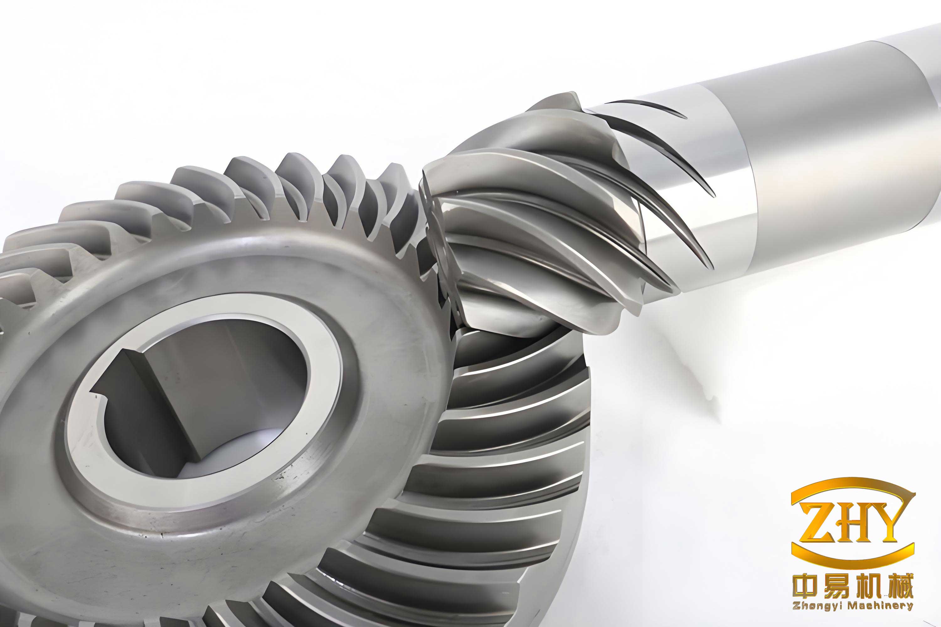
To understand the modification methodology, we must first establish the mathematical foundation for the tooth surfaces of spiral bevel gears. The process begins with the gear (often referred to as the “wheel” or “large gear”), which is assumed to be manufactured using a forming method on a machining center. This approach typically employs a conical finger-type milling cutter, where the tool path follows an arc to generate both sides of a tooth slot in a single pass, enhancing efficiency. The cutter surface, which corresponds to the gear tooth surface, can be described in the cutter coordinate system \( S_e \). The position vector \( \mathbf{r}_e \) and unit normal vector \( \mathbf{n}_e \) of the cutter surface are given by:
$$ \mathbf{r}_e = \begin{bmatrix} (r_G – u_G \sin \alpha_2) \cos \theta_G \\ (r_G – u_G \sin \alpha_2) \sin \theta_G \\ -u_G \cos \alpha_2 \end{bmatrix}, $$
$$ \mathbf{n}_e = \begin{bmatrix} -\cos \alpha_2 \cos \theta_G \\ -\cos \alpha_2 \sin \theta_G \\ \sin \alpha_2 \end{bmatrix}, $$
where \( r_G \) is the cutter tip radius, \( u_G \) and \( \theta_G \) are surface parameters, and \( \alpha_2 \) is the cutter profile angle. These equations represent the geometry of the tool, which directly imparts its form onto the gear tooth surface during machining. By transforming this surface into the gear coordinate system \( S_2 \) through a series of coordinate transformations involving machine settings such as radial distance \( S_{r2} \), angular position \( q_2 \), machine root angle \( \gamma_2 \), and horizontal offset \( X_{g2} \), we obtain the theoretical gear tooth surface:
$$ \mathbf{r}_2(u_G, \theta_G) = \mathbf{M}_{2m} \mathbf{M}_{mg} \mathbf{M}_{ge} \mathbf{r}_e, $$
$$ \mathbf{n}_2(u_G, \theta_G) = \mathbf{L}_{2m} \mathbf{L}_{mg} \mathbf{L}_{ge} \mathbf{n}_e, $$
where \( \mathbf{M}_{ij} \) and \( \mathbf{L}_{ij} \) are transformation matrices and their rotational submatrices, respectively. This gear surface serves as the reference for generating the conjugate pinion surface. For spiral bevel gears, the pinion must mesh perfectly with the gear under ideal conditions, which is achieved through conjugate theory. By establishing the meshing coordinate system and applying the condition of continuous tangency, the fully conjugate pinion tooth surface \( \mathbf{r}_1(u_G, \theta_G) \) and its unit normal \( \mathbf{n}_1(u_G, \theta_G) \) can be derived as:
$$ \mathbf{r}_1(u_G, \theta_G) = \mathbf{M}_{1h} \mathbf{M}_{hd} \mathbf{M}_{d2} \mathbf{r}_2(u_G, \theta_G), $$
$$ \mathbf{n}_1(u_G, \theta_G) = \mathbf{L}_{1h} \mathbf{L}_{hd} \mathbf{L}_{d2} \mathbf{n}_2(u_G, \theta_G), $$
where the matrices account for the relative position and orientation between the gear and pinion during meshing. However, this fully conjugate surface results in line contact, which is highly sensitive to misalignments and errors in manufacturing or assembly. To enhance robustness and control the contact pattern, modification of the pinion tooth surface is necessary. The key is to introduce controlled deviations from the conjugate surface, transforming it into a point-contact configuration that is more tolerant to variations.
The modification process begins by discretizing the conjugate pinion surface. I adopt a grid pattern similar to industry standards, such as those used by Gleason, with 9 points along the lengthwise direction and 5 points along the profile direction, resulting in 45 discrete points. Each point \( P_i(x_i, y_i, z_i) \) on the pinion surface corresponds to coordinates \( (X_{Li}, R_{Li}) \) in the rotational projection plane, related by:
$$ x_i(u_G, \theta_G) = X_{Li}, $$
$$ y_i^2(u_G, \theta_G) + z_i^2(u_G, \theta_G) = R_{Li}^2. $$
Solving these nonlinear equations yields the position vectors and normals for the discrete points on the conjugate pinion surface. Next, I apply modification by defining a target pinion surface \( \Sigma_m \) with position vector \( \mathbf{r}_m(u, \theta) \). The deviation between the target surface and the conjugate surface \( \Sigma_1 \) along the normal direction is given by the difference surface equation:
$$ \delta(u, \theta) = [\mathbf{r}_m(u, \theta) – \mathbf{r}_1(u, \theta)] \cdot \mathbf{n}_1(u, \theta). $$
This deviation can be approximated using a second-order polynomial to quantitatively control the modification:
$$ \delta = a_0 + a_1 x + a_2 y + a_3 x^2 + a_4 y^2 + a_5 x y, $$
where \( x \) and \( y \) represent coordinates in the lengthwise and profile directions, respectively, in a local modification coordinate system. The coefficients \( a_0 \) to \( a_5 \) have specific geometric interpretations: \( a_0 \) accounts for positional shifts along the normal, \( a_1 \) and \( a_2 \) influence spiral angle and pressure angle variations, and \( a_3 \), \( a_4 \), and \( a_5 \) control curvature modifications. By selecting appropriate coefficients, we can tailor the tooth surface of spiral bevel gears to achieve desired contact characteristics, such as a centered contact pattern or reduced sensitivity to errors. The target pinion surface is then constructed as:
$$ \mathbf{r}_m(u, \theta) = \mathbf{r}_1(u, \theta) + \delta \, \mathbf{n}_1(u, \theta). $$
To implement this, I establish a modification coordinate system \( S(O, X, Y, Z) \) with its origin at the intersection of the pinion pitch cone and the mid-face width. The \( X \)-axis aligns with the lengthwise direction, and the \( Y \)-axis with the profile direction. Given a modification reference point with offsets \( \Delta x \) and \( \Delta y \), the grid coordinates \( (X_{Li}, R_{Li}) \) are transformed to \( (X_i, Y_i) \) in \( S \) using:
$$ X_i = X_{Li} \cos \delta_1 + R_{Li} \sin \delta_1 – R_m + \Delta x, $$
$$ Y_i = -X_{Li} \sin \delta_1 + R_{Li} \cos \delta_1 + \Delta y, $$
where \( \delta_1 \) is the pinion pitch angle and \( R_m \) is the mean cone distance. Substituting \( (X_i, Y_i) \) into the polynomial for \( \delta \) and assigning coefficients yields the modification amount at each grid point. Adding these amounts along the normal vectors of the conjugate surface generates discrete data points for the target pinion surface of the spiral bevel gear. This quantitative approach allows for precise control over the tooth geometry, enabling optimization for specific performance criteria.
With the modified discrete points, the next step is to construct a continuous digital representation of the pinion tooth surface. I employ non-uniform rational B-spline (NURBS) surfaces, which are widely used in CAD systems for their flexibility and accuracy. A bicubic NURBS surface is defined as:
$$ \mathbf{P}(u, v) = \frac{\sum_{i=1}^n \sum_{j=1}^m B_{i,3}(u) B_{j,3}(v) w_{ij} \mathbf{V}_{ij}}{\sum_{i=1}^n \sum_{j=1}^m B_{i,3}(u) B_{j,3}(v) w_{ij}}, $$
where \( \mathbf{V}_{ij} \) are control points, \( w_{ij} \) are weights, and \( B_{i,3}(u) \) and \( B_{j,3}(v) \) are cubic B-spline basis functions in the \( u \) and \( v \) parametric directions, respectively. The fitting process involves two stages: first, computing control points for NURBS curves along the \( u \)-direction using the discrete points as data points; second, using these control points as data points to compute the surface control mesh in the \( v \)-direction. This results in a smooth, analytically representable digital pinion surface \( \mathbf{R}_1(u_1, v_1) \), where \( u_1 \) and \( v_1 \) are surface parameters. The accuracy of NURBS fitting is sufficient for gear applications, as it can capture subtle modifications without significant error. Moreover, derivatives of the surface can be computed to obtain principal directions and curvatures, which are essential for subsequent contact analysis. This digital model forms the basis for simulating the meshing behavior of the spiral bevel gear pair.
To evaluate the performance of the modified spiral bevel gear, tooth contact analysis (TCA) is conducted. TCA simulates the meshing of the digital pinion surface \( \mathbf{R}_1(u_1, v_1) \) with the theoretical gear surface \( \mathbf{r}_2(u_G, \theta_G) \). Both surfaces are transformed into a fixed coordinate system \( S_h \) attached to the gear housing. For a given pinion rotation angle \( \phi_1 \), the conditions for continuous tangency require that at the contact point, the position vectors and unit normals coincide:
$$ \mathbf{R}_h^{(1)}(u_1, v_1, \phi_1) = \mathbf{r}_h^{(2)}(u_G, \theta_G, \phi_2), $$
$$ \mathbf{n}_h^{(1)}(u_1, v_1, \phi_1) = \mathbf{n}_h^{(2)}(u_G, \theta_G, \phi_2), $$
where \( \phi_2 \) is the gear rotation angle. These vector equations yield five independent scalar equations with six unknowns: \( u_1, v_1, u_G, \theta_G, \phi_2 \), and \( \phi_1 \). By treating \( \phi_1 \) as the input and solving the system numerically, we obtain the instantaneous contact point for each position. Varying \( \phi_1 \) over a range corresponding to one mesh cycle generates the path of contact on the tooth surface. Additionally, the transmission error, which is a critical indicator of meshing smoothness for spiral bevel gears, is calculated as:
$$ \Delta \phi(\phi_1) = (\phi_2 – \phi_2^0) – (\phi_1 – \phi_1^0) \frac{z_1}{z_2}, $$
where \( \phi_1^0 \) and \( \phi_2^0 \) are initial angles, and \( z_1 \) and \( z_2 \) are the numbers of teeth on the pinion and gear, respectively. A small, parabolic transmission error curve is desirable for low noise and vibration. Furthermore, assuming elastic deformation under load, the instantaneous contact ellipse at each point can be determined based on surface curvatures. The set of contact ellipses forms the contact pattern, which should be centered on the tooth flank with appropriate size and orientation for spiral bevel gears. Through TCA, the effect of modification coefficients can be assessed, allowing iterative refinement to achieve optimal contact characteristics.
To illustrate the application of this methodology, I present a detailed example for a spiral bevel gear pair. The gear blank parameters are listed in Table 1, and the gear machining parameters are provided in Table 2. These parameters define the geometry and manufacturing setup for the spiral bevel gear, ensuring consistency in the analysis.
| Parameter | Pinion | Gear |
|---|---|---|
| Hand of Spiral | Left | Right |
| Number of Teeth | 8 | 37 |
| Whole Depth (mm) | 19.668 | 19.668 |
| Addendum (mm) | 14.135 | 3.575 |
| Dedendum (mm) | 5.533 | 16.093 |
| Pitch Angle (°) | 12.20 | 77.799 |
| Face Angle (°) | 16.62 | 79.321 |
| Root Angle (°) | 10.67 | 73.379 |
| Face Width (mm) | 60 | 60 |
| Mean Cone Distance (mm) | 178.202 | 178.202 |
| Spiral Angle (°) | 35 | 35 |
| Pressure Angle (°) | 20 | 20 |
| Shaft Angle (°) | 90 | 90 |
| Machining Parameter | Value |
|---|---|
| Radial Distance (mm) | 153.9826 |
| Angular Position (°) | 51.3485 |
| Machine Root Angle (°) | 73.91667 |
| Axial Offset (mm) | -1.82 |
| Blank Offset (mm) | 0 |
| Outside Blade Profile Angle (°) | -20 |
| Inside Blade Profile Angle (°) | 20 |
| Cutter Offset (mm) | 7.0 |
| Cutter Radius (mm) | 152.4 |
For the pinion concave side, I apply modification using the coefficients in Table 3. These coefficients are chosen to introduce slight curvature changes, aiming for a favorable contact pattern. The modification amounts are computed and superimposed on the conjugate pinion surface, resulting in the target discrete points. The deviation between the target and conjugate surfaces is visualized as a contour plot, showing maximum modification at the toe and heel regions near the root and tip, which is typical for spiral bevel gears to avoid edge contact.
| Coefficient | a0 | a1 | a2 | a3 | a4 | a5 |
|---|---|---|---|---|---|---|
| Value | 0 | 0 | 0 | 0.0002 | 0.0013 | 0 |
After fitting the digital pinion surface with NURBS, TCA is performed. The results include the transmission error curve and the contact pattern on the gear convex side. The transmission error exhibits a parabolic shape with minimal fluctuation, indicating smooth meshing. The contact pattern is centered on the tooth flank with a size appropriate for the load distribution, demonstrating the effectiveness of the modification for spiral bevel gears. This simulation confirms that the selected coefficients yield desirable meshing characteristics, validating the modification design process.
To experimentally verify the method, I conducted cutting trials on a DMG DMU40 five-axis machining center. The digital pinion model, derived from the modified discrete points, was imported into CAD/CAM software (e.g., Siemens NX) to generate tool paths. The machining sequence involved roughing with a 12 mm diameter finger-type end mill, semi-finishing with a 6 mm diameter finger mill, and finishing with a 4 mm diameter ball-end mill. This tool selection leverages the flexibility of machining centers, allowing for efficient material removal and precise surface generation for spiral bevel gears. The cutting parameters, such as feed rate and spindle speed, were optimized based on tool material and gear steel hardness. The total machining time for the pinion was approximately 20 minutes for roughing, plus additional time for semi-finishing and finishing, highlighting the efficiency compared to traditional dedicated gear cutters.
After machining, the pinion was paired with the gear (manufactured separately using forming method) for rolling contact tests. The gear was coated with a thin layer of marking compound, and the pair was run under light load in a testing machine. The resulting contact pattern on the gear tooth was photographed and compared with the TCA simulation. The experimental contact pattern closely matched the predicted one in terms of location, size, and shape, confirming the accuracy of the digital model and the modification approach for spiral bevel gears. Minor discrepancies could be attributed to factors like machine tool accuracy, tool wear, or assembly errors, but the overall agreement validates the feasibility of implementing tooth surface modification on machining centers.
The success of this experiment underscores several advantages of using machining centers for spiral bevel gear production. First, the use of standard cutting tools (e.g., end mills and ball-end mills) reduces tooling costs compared to specialized gear cutters. Second, the flexibility of CNC programming allows for rapid prototyping and adjustment of modification parameters without physical tool changes. Third, the integration of CAD/CAM and digital surface modeling enables precise control over tooth geometry, facilitating high-quality gear manufacturing. Moreover, this approach can be extended to hard machining (e.g., using carbide tools) for case-hardened spiral bevel gears, potentially eliminating the need for separate grinding operations.
In conclusion, I have developed a comprehensive methodology for tooth surface modification of spiral bevel gears based on machining center cutting. The core contributions include: (1) a quantitative modification technique using a second-order difference surface equation applied to the conjugate pinion surface, enabling controlled deviations for improved meshing performance; (2) digital surface reconstruction via NURBS fitting, providing an accurate model for analysis and manufacturing; and (3) validation through TCA simulations and experimental cutting on a five-axis machining center. The results demonstrate that the proposed method effectively generates desirable contact patterns and transmission error characteristics for spiral bevel gears, bridging the gap between advanced manufacturing platforms and gear quality control.
This research paves the way for broader adoption of machining centers in gear production, particularly for spiral bevel gears used in aerospace, automotive, and industrial applications. Future work could focus on optimizing modification coefficients for dynamic load conditions, integrating real-time monitoring during machining, and extending the method to other gear types such as hypoid gears. By leveraging the capabilities of modern CNC systems, we can achieve a paradigm shift in gear manufacturing—toward more flexible, cost-effective, and high-precision production of spiral bevel gears.