
In the field of hydraulic systems, the demand for pumps capable of operating under high-speed and high-pressure conditions has significantly increased, particularly in aerospace, power generation, and advanced manufacturing applications. Among various pump types, the spiral gear pump, characterized by its helical or circular arc gear profile, offers distinct advantages such as low flow pulsation, reduced noise, and the absence of trapped fluid phenomena compared to traditional involute gear pumps. However, we have observed that under extreme operational conditions, these spiral gear pumps experience a severe imbalance in radial forces, leading to accelerated wear of sliding bearings, increased temperature rise, and leakage, ultimately compromising efficiency and lifespan. This study aims to address this critical issue by developing a novel radial force compensation method specifically for high-speed high-pressure spiral gear pumps.
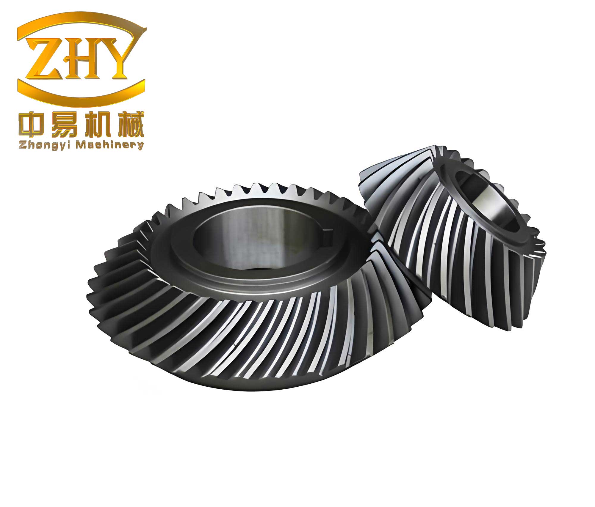
The fundamental working principle of a spiral gear pump involves the meshing of two helical gears with a unique tooth profile, often a combination of circular arcs and sinusoidal curves. This design ensures continuous engagement and fluid displacement with minimal pulsation. The term “spiral gear” here refers to the helical nature of the gears, which provides axial overlap and smooth operation. Despite these benefits, the inherent fluid pressure distribution and gear meshing actions generate substantial radial loads on the gear shafts. At elevated speeds and pressures, these loads become disproportionately large, posing a significant challenge for conventional bearing systems. Our investigation focuses on quantifying these forces and designing a compensatory mechanism integrated into the sliding bearings.
To systematically analyze the problem, we first established a comprehensive mathematical model for the forces acting on the gear shaft in a spiral gear pump. The total radial force (\(F_r\)) is a vector sum of two primary components: the hydraulic radial force (\(F_P\)) generated by the pressure difference between the inlet and outlet chambers acting on the gear tooth surfaces, and the force (\(F_N\)) arising from the gear meshing torque. For a spiral gear pump, the hydraulic force can be derived by considering the pressure distribution over the gear circumference. Assuming the pressure varies linearly from the low-pressure suction side to the high-pressure discharge side, the components of \(F_P\) in the x and y directions are given by:
$$F_{Px} = \Delta p \cdot b \cdot r \cdot \frac{\cos \theta_2 – \cos \theta_1}{\theta_2 – \theta_1}$$
$$F_{Py} = \Delta p \cdot b \cdot r \cdot \left(1 – \frac{\sin \theta_2 – \sin \theta_1}{\theta_2 – \theta_1}\right)$$
where \(\Delta p\) is the pressure difference between the discharge and suction ports, \(b\) is the gear width, \(r\) is the average radius (\(r = (r_a + r_b)/2\)), with \(r_a\) and \(r_b\) being the tip and root circle radii, respectively. \(\theta_1\) and \(\theta_2\) are the angles defining the low and high-pressure zones relative to the gear center. The resultant hydraulic radial force is \(F_P = \sqrt{F_{Px}^2 + F_{Py}^2}\). The meshing force \(F_N\) is calculated from the transmitted torque \(T\), the base circle radius \(R_b\), and the pressure angle \(\alpha\):
$$F_N = \frac{T}{R_b}$$
with its components being \(F_{Nx} = F_N \sin \alpha\) and \(F_{Ny} = F_N \cos \alpha\). The total radial force on the driven gear shaft, which typically experiences a larger load due to the acute angle between force vectors, is:
$$F_{r2} = \sqrt{F_P^2 + F_N^2 + 2 F_N F_P \cos \alpha}$$
For the driving gear, the force is \(F_{r1} = \sqrt{F_P^2 + F_N^2 – 2 F_N F_P \cos \alpha}\). Our calculations indicate that in a typical high-pressure scenario of 25 MPa and high speed of 10,000 rpm, the radial force on the driven shaft of a spiral gear pump can exceed several thousand Newtons, necessitating an effective compensation strategy.
Conventional methods, such as using balanced gear designs or optimizing pump casing geometry, often fall short under these extreme conditions due to complexity or manufacturing constraints. Therefore, we propose an innovative sliding bearing design that actively compensates for the unbalanced radial force. The core idea is to utilize the high-pressure oil from the pump’s discharge chamber itself to generate a counteracting force. This is achieved by introducing dedicated hydrostatic pockets (or recesses) on the bearing surface, which are supplied directly with high-pressure oil via an inlet port connected to the discharge side. The pressurized oil in these pockets exerts a force on the gear shaft, effectively offsetting a significant portion of the net radial load.
The geometry of the hydrostatic pocket is crucial for effective compensation. Since the dominant component of the radial force acts primarily along the y-axis (line connecting the gear centers), we designed symmetrical pockets oriented to oppose this force. The required projected area of the pocket to generate a compensating force \(F_h\) equal to \(F_{ry}\) (the y-component of the total radial force) is determined by:
$$F_h = \frac{p \cdot b_1 \cdot \theta \cdot D_z}{180}$$
where \(p\) is the supply pressure (approximately equal to discharge pressure), \(b_1\) is the axial width of the pocket, \(\theta\) is the angular extent of the pocket in degrees, and \(D_z\) is the bearing inner diameter (equal to the journal diameter). Rearranging, the pocket angle is \(\theta = \frac{180 \cdot F_{ry}}{p \cdot b_1 \cdot D_z}\). For our spiral gear pump prototype, calculations yielded \(\theta \approx 156^\circ\) for the driven shaft bearing. The bearing inner diameter was selected based on both strength constraints and leakage considerations, resulting in a range of 9.8 mm to 14.4 mm. We chose \(D_z = 12\) mm to balance structural integrity and fluid dynamics performance. The complete parameters of our novel sliding bearing are summarized in Table 1.
| Parameter | Symbol | Value |
|---|---|---|
| Bearing Inner Diameter | \(D_z\) | 12 mm |
| Bearing Outer Diameter | \(D\) | 25.36 mm |
| Bearing Width | \(B\) | 19 mm |
| Oil Inlet Diameter | \(d\) | 1.5 mm |
| Hydrostatic Pocket Width | \(b_1\) | 14 mm |
| Hydrostatic Pocket Depth | \(h\) | 1 mm |
| Pocket Angular Extent | \(\theta\) | 156° |
| Feeding Groove Width | \(b_2\) | 2 mm |
To evaluate the performance of this novel bearing design, we conducted a detailed computational fluid dynamics (CFD) analysis using ANSYS Fluent software. A three-dimensional model of the oil film between the bearing and the journal was created. The fluid domain was meshed with structured hexahedral elements using ICEM CFD to ensure accuracy in capturing pressure and velocity gradients. The governing equations for the incompressible, laminar flow of hydraulic oil were solved. These include the continuity equation and the Navier-Stokes equations, which in vector form for steady flow are:
$$\nabla \cdot \vec{v} = 0$$
$$\rho (\vec{v} \cdot \nabla) \vec{v} = -\nabla p + \mu \nabla^2 \vec{v}$$
where \(\vec{v}\) is the velocity vector, \(\rho\) is the density, \(p\) is the pressure, and \(\mu\) is the dynamic viscosity. Energy equation with viscous heating was also activated to model temperature rise. The boundary conditions were set as follows: the bearing pocket inlet was defined as a pressure-inlet boundary with a gauge pressure equal to the pump discharge pressure (varied from 5 to 25 MPa in simulations). The two axial ends of the bearing were set as pressure-outlet boundaries at atmospheric pressure. The journal surface was assigned a rotational speed of 10,000 rpm, and no-slip conditions were applied to all walls. The lubricant properties were defined for a standard hydraulic oil (ISO VG 46) with density \(\rho = 870\ \text{kg/m}^3\) and viscosity \(\mu = 0.048\ \text{Pa·s}\) at 40°C.
We compared the performance of our novel hydrostatic-hybrid bearing against a conventional plain sliding bearing under identical operating conditions. The key metrics analyzed were bearing load capacity and maximum oil film temperature. The load capacity was calculated by integrating the pressure field over the journal surface. Table 2 presents a comparison of the simulated load capacity at a constant speed of 10,000 rpm for different discharge pressures.
| Discharge Pressure (MPa) | Load Capacity – Novel Bearing (N) | Load Capacity – Conventional Bearing (N) | Improvement Factor |
|---|---|---|---|
| 5 | 1250 | 380 | 3.29 |
| 10 | 2480 | 520 | 4.77 |
| 15 | 3720 | 610 | 6.10 |
| 20 | 4950 | 680 | 7.28 |
| 25 | 6180 | 650 | 9.51 |
The results clearly demonstrate the superior performance of the novel spiral gear pump bearing. At the rated pressure of 25 MPa, the novel bearing supports a load of approximately 6180 N, which is about 9.5 times greater than the 650 N supported by the conventional bearing. This dramatic increase is due to the hydrostatic pressure in the pockets, which scales linearly with the supply pressure. The pressure contour plots from the simulation vividly show that in the novel bearing, the high pressure from the discharge port is maintained within the hydrostatic pockets without significant pressure drop, creating a substantial opposing force. In contrast, the conventional bearing relies solely on hydrodynamic wedge action, which generates much lower peak pressures that are not directly proportional to the discharge pressure.
The relationship between the compensating hydrostatic force \(F_h\) and the system pressure can be expressed as:
$$F_h \propto A_{eff} \cdot p_{discharge}$$
where \(A_{eff}\) is the effective area of the hydrostatic pocket. This linear relationship explains the strong correlation observed in our simulations. The load capacity \(W\) of the conventional bearing, governed by hydrodynamic theory, depends on factors like speed, viscosity, and eccentricity ratio (\(\epsilon\)), and can be estimated by formulas such as:
$$W = \frac{\mu \omega R L^3}{c^2} f(\epsilon)$$
where \(\omega\) is angular speed, \(R\) is journal radius, \(L\) is bearing length, \(c\) is radial clearance, and \(f(\epsilon)\) is a function of eccentricity. This dependence on speed and viscosity, rather than directly on system pressure, limits its capacity under high-pressure conditions prevalent in spiral gear pumps.
Another critical aspect is the thermal performance. Excessive friction and shear in the oil film lead to temperature rise, which can degrade the lubricant and cause thermal deformation. Our CFD simulations included energy equation solving to capture this effect. Table 3 compares the maximum oil film temperature rise (above the inlet temperature of 40°C) for both bearings at 10,000 rpm.
| Discharge Pressure (MPa) | Temperature Rise – Novel Bearing (°C) | Temperature Rise – Conventional Bearing (°C) |
|---|---|---|
| 5 | 8.2 | 15.7 |
| 10 | 11.5 | 21.3 |
| 15 | 14.8 | 26.8 |
| 20 | 18.1 | 32.4 |
| 25 | 21.5 | 38.0 |
The novel bearing exhibits a significantly lower temperature rise. At 25 MPa, the temperature rise is about 21.5°C compared to 38.0°C for the conventional bearing—a reduction of nearly 16.5°C. This is primarily because the hydrostatic effect in the novel bearing reduces the eccentricity of the journal, leading to a more uniform oil film thickness and lower shear rates. The reduced contact and wear between the journal and bearing surface directly translate to lower frictional heating. The temperature distribution plots show that the hottest region in the conventional bearing is located opposite the inlet due to severe film squeezing at high eccentricity, whereas the novel bearing has a more moderate and evenly distributed temperature profile.
The benefits of radial force compensation in a spiral gear pump extend beyond just bearing life. By stabilizing the gear shaft and minimizing its radial displacement, the optimal radial clearance between the gear tips and the pump housing is maintained. This is crucial for controlling internal leakage, a major source of volumetric efficiency loss in gear pumps. The theoretical radial leakage flow \(Q_r\) in a spiral gear pump can be modeled using the parallel plate flow theory, considering both pressure-driven flow and shear-driven (Couette) flow due to gear rotation:
$$Q_r = \frac{\Delta p \cdot \delta^3}{6 \mu W} – \left( \frac{1}{30\pi} n r_a \delta \right) b \cos \beta \times 60 \times 10^3$$
Here, \(\delta\) is the radial clearance, \(W\) is the total width of the gear tip land in the transition zone, \(n\) is rotational speed in rpm, and \(\beta\) is the helix angle of the spiral gear. A stable shaft position ensured by our bearing design helps keep \(\delta\) close to its optimal design value, thereby minimizing \(Q_r\) and enhancing overall pump efficiency.
To validate our numerical findings, we conducted experimental tests on a prototype spiral gear pump equipped with both the conventional and the novel sliding bearings. The test rig comprised a tank, filters, a servo-motor drive, the test pump, pressure and temperature sensors, and a loading valve. The pump was operated at a constant speed of 6,000 rpm and a discharge pressure of 15 MPa. We measured the external casing temperature near the bearing housing over time using an infrared thermometer as an indicator of internal thermal activity and friction. The results are summarized in Table 4.
| Time (minutes) | Casing Temp. with Novel Bearing (°C) | Casing Temp. with Conventional Bearing (°C) |
|---|---|---|
| 0 | 25.0 | 25.0 |
| 10 | 38.5 | 46.2 |
| 20 | 45.1 | 58.7 |
| 30 | 48.9 | 65.3 |
| 40 | 51.0 | 68.8 |
| 50 | 52.1 | 70.5 |
After 50 minutes of operation, the pump with the novel bearing stabilized at a casing temperature of about 52.1°C, while the one with the conventional bearing reached 70.5°C—a difference of over 18°C. This experimental temperature rise trend confirms the CFD predictions and underscores the effectiveness of the radial force compensation in reducing frictional losses and heat generation. Furthermore, upon disassembly, visual inspection revealed severe wear marks on the conventional bearing surface, indicating metal-to-metal contact under the high radial load. In contrast, the novel bearing showed only mild polishing wear, confirming that the hydrostatic pockets successfully carried the majority of the load, protecting the bearing surface.
The success of this compensation method hinges on the precise design of the hydrostatic pocket and the supply system. The pocket depth \(h\) must be sufficient to ensure adequate oil flow and pressure distribution but not so large as to cause excessive leakage. The feeding groove (\(b_2\)) ensures even distribution of oil to the pocket. An important design consideration is the dynamic response of this system. Since the supply pressure to the pocket is directly taken from the pump’s discharge, any pressure fluctuation in the spiral gear pump will be instantly reflected in the compensating force. This provides inherent dynamic stability. The stiffness of the bearing, defined as the change in force per unit displacement (\(K = dF/dx\)), is significantly higher for the hydrostatic-hybrid design compared to a purely hydrodynamic bearing, leading to better vibration damping and positional accuracy of the gear shaft.
In conclusion, our research presents a highly effective solution to the challenging problem of radial force imbalance in high-speed high-pressure spiral gear pumps. By integrating a simple yet ingenious hydrostatic compensation mechanism into the sliding bearings, we have demonstrated a multi-fold increase in load-carrying capacity and a substantial reduction in operating temperature. The mathematical models, CFD simulations, and experimental tests collectively validate the design. The novel bearing not only extends the service life of the pump components but also contributes to higher volumetric efficiency by stabilizing internal clearances. This advancement holds great promise for enhancing the performance and reliability of spiral gear pumps in demanding hydraulic applications. Future work may explore optimization of pocket geometry for different spiral gear profiles, investigation of transient behaviors during start-up and pressure surges, and the integration of this concept into multi-stage or multi-pump configurations.
The development and analysis detailed here underscore the critical interplay between fluid dynamics, structural mechanics, and thermal management in the design of advanced spiral gear pumps. The use of hydrostatic principles for load compensation offers a robust pathway to overcome the limitations imposed by extreme operational conditions, paving the way for the next generation of efficient and durable hydraulic power units. The spiral gear, with its inherent advantages, can now be more effectively utilized in systems where high power density and smooth operation are paramount, thanks to innovations in supporting bearing technology like the one we have presented.