
In the realm of gear manufacturing, the production of spiral gears has always presented unique challenges due to their complex geometry and the precision required for proper meshing. As an engineer specializing in gear machining, I have encountered numerous situations where traditional differential hobbing methods fall short, particularly when workpiece tooth counts and indexing constants are incompatible or when the spiral angle is too small to compute a feasible differential ratio. These limitations often lead to approximate calculations, introducing errors that can compromise the quality of spiral gear pairs. In this article, I introduce a new non-differential hobbing method that overcomes these issues, offering a precise alternative that is especially valuable for machines lacking differential mechanisms. This approach not only eliminates the need for differential gear trains but also ensures accurate spiral angle matching between mating gears, thereby enhancing the performance and longevity of spiral gear systems. Throughout this discussion, I will delve into the theoretical foundations, provide detailed formulas, and illustrate the method with practical examples, all while emphasizing the critical role of spiral gears in modern machinery.
The fundamental principle behind hobbing spiral gears lies in the synchronized rotation of the workpiece and the hob, coupled with axial feed to generate the helical teeth. In conventional differential hobbing, a differential gearbox is used to adjust the relative motion, accounting for the lead of the spiral gear. However, when the differential ratio cannot be precisely calculated or when the machine is not equipped with such a mechanism, manufacturers often resort to non-differential methods, which have historically been less accurate. My new method addresses this by reformulating the indexing and feed calculations to avoid approximations, ensuring that the spiral angle is exact and consistent for both gears in a pair. This is crucial for spiral gears, as any deviation in helix angle can lead to uneven load distribution, noise, and premature failure. The core idea revolves around manipulating the feed rate parameter to achieve integer values in the indexing formula, thereby enabling exact computation of change gears without reliance on differentials.
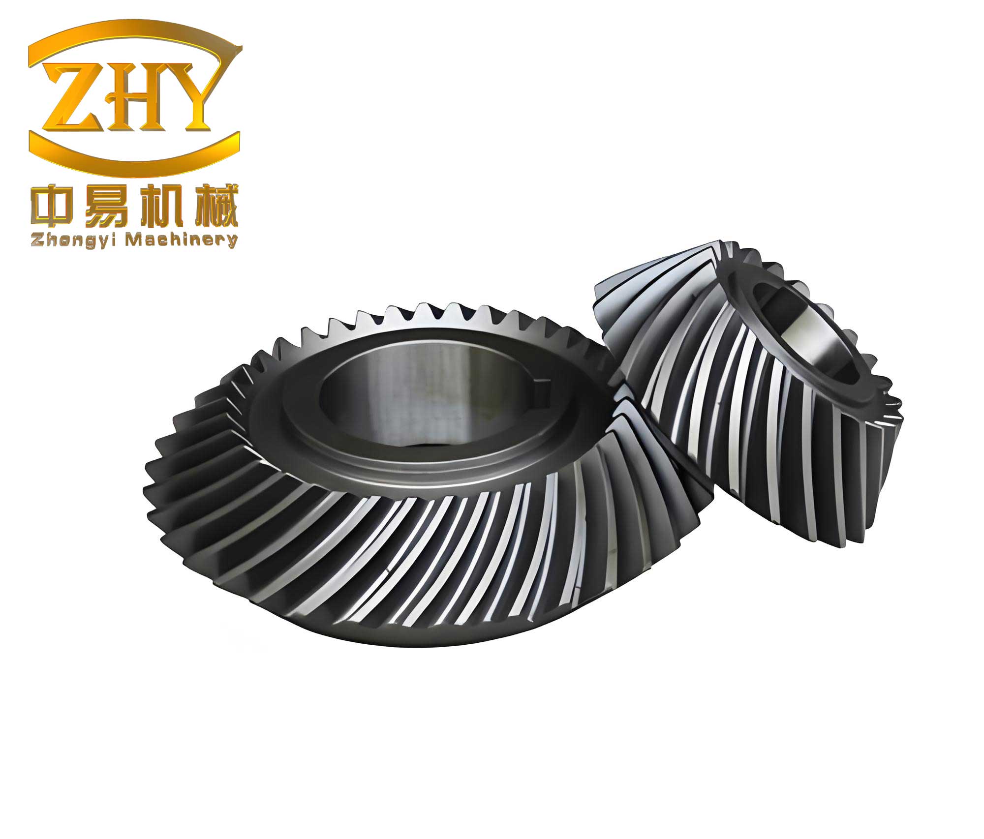
To understand this method, let’s start with the basic kinematics of spiral gear hobbing. Consider a spiral gear with a number of teeth denoted by $z_w$, and a hob with a number of starts $k$. For cutting a spur gear, the relationship is straightforward: when the hob rotates once, the workpiece rotates by $k/z_w$ turns. However, for spiral gears, the axial movement of the hob along the workpiece axis introduces an additional rotational component due to the lead $L$ of the spiral gear. If the hob moves a distance equal to $L$ without rotation, the workpiece would complete one full rotation. In practice, during hobbing, the feed rate $s$ (in mm per revolution of the workpiece) determines the axial displacement per workpiece revolution. The total rotation of the workpiece relative to the hob must account for both the indexing motion and the helical lead. This leads to the fundamental equation for non-differential hobbing of spiral gears:
$$ \frac{k}{z_w} \pm \frac{s}{L} = \frac{a}{b} $$
Here, $a$ and $b$ are integers representing the change gear ratio for indexing, and the $\pm$ sign depends on the relative directions of the hob and workpiece rotation (positive for same direction, negative for opposite). The lead $L$ of the spiral gear is given by $L = \frac{\pi m z_w}{\sin \beta}$, where $m$ is the module and $\beta$ is the spiral angle. Substituting this into the equation, we get:
$$ \frac{k}{z_w} \pm \frac{s \sin \beta}{\pi m z_w} = \frac{a}{b} $$
Rearranging terms, the indexing change gear ratio can be expressed as:
$$ \frac{a}{b} = \frac{k}{z_w} \left(1 \pm \frac{s \sin \beta}{\pi m k}\right) $$
In traditional non-differential methods, this ratio often results in fractional values that require approximate gear selections, leading to errors in the spiral angle. The key innovation in my approach is to select the feed rate $s$ such that the term $\frac{s \sin \beta}{\pi m k}$ becomes a rational number with integer numerator and denominator, allowing $\frac{a}{b}$ to be computed exactly. Specifically, we set:
$$ \frac{s \sin \beta}{\pi m k} = \frac{p}{q} $$
where $p$ and $q$ are integers. Then, the indexing formula simplifies to:
$$ \frac{a}{b} = \frac{k}{z_w} \left(1 \pm \frac{p}{q}\right) = \frac{k(q \pm p)}{z_w q} $$
Since $k$, $p$, $q$, and $z_w$ are integers, we can choose $q$ to make $z_w q$ a multiple of $k(q \pm p)$, ensuring that $\frac{a}{b}$ is an exact fraction. This eliminates approximations in the indexing change gears. The feed rate $s$ is then derived from the relation:
$$ s = \frac{\pi m k p}{\sin \beta q} $$
By carefully selecting $p$ and $q$, we can achieve a feed rate within practical limits while maintaining precision. This method ensures that for a pair of mating spiral gears, the same feed rate can be used, and any errors from the feed change gear approximation cancel out, just as in differential hobbing. This is because the spiral angle $\beta$ is inherently controlled by the exact indexing ratio, and the feed rate only affects the axial movement, which is common to both gears.
To illustrate the process, let’s consider a detailed example involving the hobbing of a pair of spiral gears on a Y3150 type gear hobbing machine. This machine lacks a differential mechanism, making it ideal for applying this non-differential method. The parameters for the spiral gears are as follows: both gears have a module $m = 5$ mm and a spiral angle $\beta = 15^\circ$. The large gear is right-handed with $z_w = 80$ teeth, and the small gear is left-handed with $z_w = 30$ teeth. We use a single-start right-handed hob ($k = 1$), and we aim for a feed rate around $s = 2$ mm per revolution. The goal is to compute the change gears for indexing and feed without any differential setup.
First, we calculate the lead $L$ for both spiral gears using $L = \frac{\pi m z_w}{\sin \beta}$. For the large gear:
$$ L_{\text{large}} = \frac{\pi \times 5 \times 80}{\sin 15^\circ} = \frac{400\pi}{0.258819} \approx 4850.85 \text{ mm} $$
For the small gear:
$$ L_{\text{small}} = \frac{\pi \times 5 \times 30}{\sin 15^\circ} = \frac{150\pi}{0.258819} \approx 1819.07 \text{ mm} $$
Next, we determine the parameters $p$ and $q$ to satisfy the condition $\frac{s \sin \beta}{\pi m k} = \frac{p}{q}$. Using the desired feed rate $s = 2$ mm/rev, we compute:
$$ \frac{s \sin \beta}{\pi m k} = \frac{2 \times \sin 15^\circ}{\pi \times 5 \times 1} = \frac{2 \times 0.258819}{15.70796} \approx 0.03297 $$
We approximate this fraction with integers. For instance, $0.03297 \approx \frac{1}{30} = 0.03333$, so we set $p = 1$ and $q = 30$. This gives an adjusted feed rate from the formula $s = \frac{\pi m k p}{\sin \beta q}$:
$$ s = \frac{\pi \times 5 \times 1 \times 1}{\sin 15^\circ \times 30} = \frac{15.70796}{0.258819 \times 30} \approx \frac{15.70796}{7.76457} \approx 2.023 \text{ mm/rev} $$
This feed rate is close to the original 2 mm/rev and is acceptable for practical purposes. Now, we compute the indexing change gear ratio $\frac{a}{b}$ for both spiral gears. Since the large gear is right-handed (same direction as the hob), we use the positive sign in the formula; for the small left-handed gear, we use the negative sign.
For the large spiral gear:
$$ \frac{a}{b} = \frac{k(q + p)}{z_w q} = \frac{1 \times (30 + 1)}{80 \times 30} = \frac{31}{2400} $$
For the small spiral gear:
$$ \frac{a}{b} = \frac{k(q – p)}{z_w q} = \frac{1 \times (30 – 1)}{30 \times 30} = \frac{29}{900} $$
These fractions are exact, allowing us to select change gears with precise tooth counts. Typically, on the Y3150 machine, the indexing change gear train uses a compound gear setup with specific available gears. We can factor these ratios to match available gears. For example, $\frac{31}{2400}$ can be approximated as $\frac{31}{2400} = \frac{31}{24 \times 100}$, but since exact gears might not exist, we use the closest available gears. However, the key point is that the ratio is exact in theory, and any practical gear selection will minimize error compared to approximate methods.
Now, for the feed change gears, the formula on the Y3150 machine is given by:
$$ \frac{c}{d} = \frac{s}{t} $$
where $t$ is a constant related to the machine’s feed mechanism (often $t = 3$ mm/rev for such machines). Using our adjusted feed rate $s = 2.023$ mm/rev, we get:
$$ \frac{c}{d} = \frac{2.023}{3} \approx 0.6743 $$
This can be approximated with available gears, e.g., $\frac{67}{100} = 0.67$ or $\frac{101}{150} \approx 0.6733$. Since the same feed rate is used for both spiral gears, any error in this approximation cancels out for the pair, ensuring identical spiral angles.
To summarize the calculations, I present the following tables for clarity:
| Parameter | Large Spiral Gear | Small Spiral Gear | Common Values |
|---|---|---|---|
| Number of Teeth ($z_w$) | 80 | 30 | — |
| Spiral Angle ($\beta$) | 15° (right-handed) | 15° (left-handed) | 15° |
| Module ($m$) | 5 mm | 5 mm | 5 mm |
| Hob Starts ($k$) | 1 (right-handed) | 1 (right-handed) | 1 |
| Lead ($L$) | 4850.85 mm | 1819.07 mm | — |
| Desired Feed Rate ($s$) | 2 mm/rev | 2 mm/rev | 2 mm/rev |
| Adjusted Feed Rate ($s$) | 2.023 mm/rev | 2.023 mm/rev | 2.023 mm/rev |
| Component | Formula | Large Spiral Gear Result | Small Spiral Gear Result |
|---|---|---|---|
| Indexing Ratio ($\frac{a}{b}$) | $\frac{k(q \pm p)}{z_w q}$ | $\frac{31}{2400}$ | $\frac{29}{900}$ |
| Feed Ratio ($\frac{c}{d}$) | $\frac{s}{t}$ with $t=3$ | $\approx 0.6743$ | $\approx 0.6743$ |
| Selected Indexing Gears | Based on available gears | e.g., 31/240 compound | e.g., 29/90 compound |
| Selected Feed Gears | Based on available gears | e.g., 67/100 or 101/150 | Same as large gear |
The advantages of this non-differential method are manifold. First, it enables precise manufacturing of spiral gears on machines without differential mechanisms, expanding the capability of older or simpler equipment. Second, by eliminating approximations in indexing change gears, it ensures accurate spiral angles, which is critical for the proper meshing of gear pairs. In traditional non-differential hobbing, approximate gear selections lead to slight variations in spiral angle between mating gears, causing alignment issues and reduced efficiency. With this new approach, the spiral angle is inherently controlled by the exact indexing ratio, and the feed rate approximation error is common to both gears, thus canceling out. This results in spiral gears that mesh smoothly, distribute loads evenly, and operate quietly—key requirements for high-performance applications such as automotive transmissions, industrial machinery, and aerospace systems.
To further validate the method, let’s verify the spiral angle using the derived formulas. From the indexing ratio, we can back-calculate the effective spiral angle. Starting from the relation:
$$ \frac{a}{b} = \frac{k}{z_w} \left(1 \pm \frac{s \sin \beta}{\pi m k}\right) $$
Rearranging for $\sin \beta$:
$$ \sin \beta = \frac{\pi m k}{s} \left( \frac{a}{b} \cdot \frac{z_w}{k} – 1 \right) $$
For the large spiral gear, using the exact ratio $\frac{a}{b} = \frac{31}{2400}$, $z_w = 80$, $k=1$, $s=2.023$ mm/rev, and $m=5$ mm:
$$ \sin \beta = \frac{\pi \times 5 \times 1}{2.023} \left( \frac{31}{2400} \times \frac{80}{1} – 1 \right) = \frac{15.70796}{2.023} \left( \frac{31 \times 80}{2400} – 1 \right) $$
$$ = 7.764 \left( \frac{2480}{2400} – 1 \right) = 7.764 \left( 1.03333 – 1 \right) = 7.764 \times 0.03333 \approx 0.2588 $$
Thus, $\beta = \arcsin(0.2588) \approx 15.00^\circ$, confirming the spiral angle. Similarly, for the small spiral gear with $\frac{a}{b} = \frac{29}{900}$ and $z_w = 30$:
$$ \sin \beta = \frac{15.70796}{2.023} \left( \frac{29}{900} \times \frac{30}{1} – 1 \right) = 7.764 \left( \frac{870}{900} – 1 \right) = 7.764 \left( 0.96667 – 1 \right) = 7.764 \times (-0.03333) \approx -0.2588 $$
The negative sign indicates the opposite helix direction, but the magnitude gives $\beta \approx 15.00^\circ$. This demonstrates that both spiral gears have identical spiral angles, ensuring perfect meshing.
In comparison to differential hobbing, this method offers comparable precision without the complexity of differential gear trains. Differential hobbing typically requires calculating a differential ratio $i_d$ from the formula $i_d = \frac{C \sin \beta}{m k}$, where $C$ is a machine constant. When $\beta$ is small or $z_w$ and the indexing constant are incompatible, $i_d$ may become impractical to set with available change gears, forcing approximations. In contrast, the non-differential method allows flexibility in feed rate selection to achieve exact indexing ratios. This is particularly beneficial for spiral gears with high tooth counts or unusual modules, where differential setups might be limited. Additionally, for shops with multiple machines, this approach standardizes processes across equipment with and without differentials, reducing setup times and training requirements.
The application of this method extends beyond standard spiral gears to include variants such as double-helical gears or gears with modified tooth profiles. By adjusting the parameters $p$ and $q$, one can tailor the feed rate to achieve optimal cutting conditions while maintaining accuracy. For instance, in high-volume production of spiral gears for automotive differentials, this method can enhance consistency and reduce scrap rates. Moreover, it facilitates the use of advanced hobbing techniques like climb hobbing or dry hobbing, as the precise control over indexing minimizes vibrations and tool wear. As spiral gears continue to evolve with demands for higher loads and quieter operation, such manufacturing innovations become increasingly valuable.
To implement this method in practice, I recommend the following steps: First, determine the workpiece parameters—module, number of teeth, and spiral angle—for the spiral gear. Second, select a hob with appropriate starts and handedness. Third, choose a target feed rate based on material and machine capabilities. Fourth, compute the fraction $\frac{s \sin \beta}{\pi m k}$ and approximate it with integers $p$ and $q$ to achieve a practical feed rate. Fifth, calculate the exact indexing ratio using $\frac{a}{b} = \frac{k(q \pm p)}{z_w q}$. Sixth, select available change gears to match this ratio as closely as possible. Seventh, compute the feed change gears based on the adjusted feed rate. Finally, set up the machine and perform test cuts to verify the spiral angle. This process ensures that every spiral gear produced meets specifications with minimal error.
In conclusion, the non-differential hobbing method presented here represents a significant advancement in the manufacturing of spiral gears. By leveraging mathematical ingenuity to eliminate approximations in indexing, it delivers precision on par with differential methods, even on machines lacking differential mechanisms. This not only broadens the accessibility of high-quality spiral gear production but also enhances the reliability and performance of gear systems across industries. As I continue to explore gear machining techniques, I am confident that such approaches will play a pivotal role in advancing mechanical engineering and supporting the development of more efficient and durable machinery. The spiral gear, with its unique geometry and functional benefits, remains at the heart of this progress, and methods like this ensure it can be manufactured to the highest standards.