
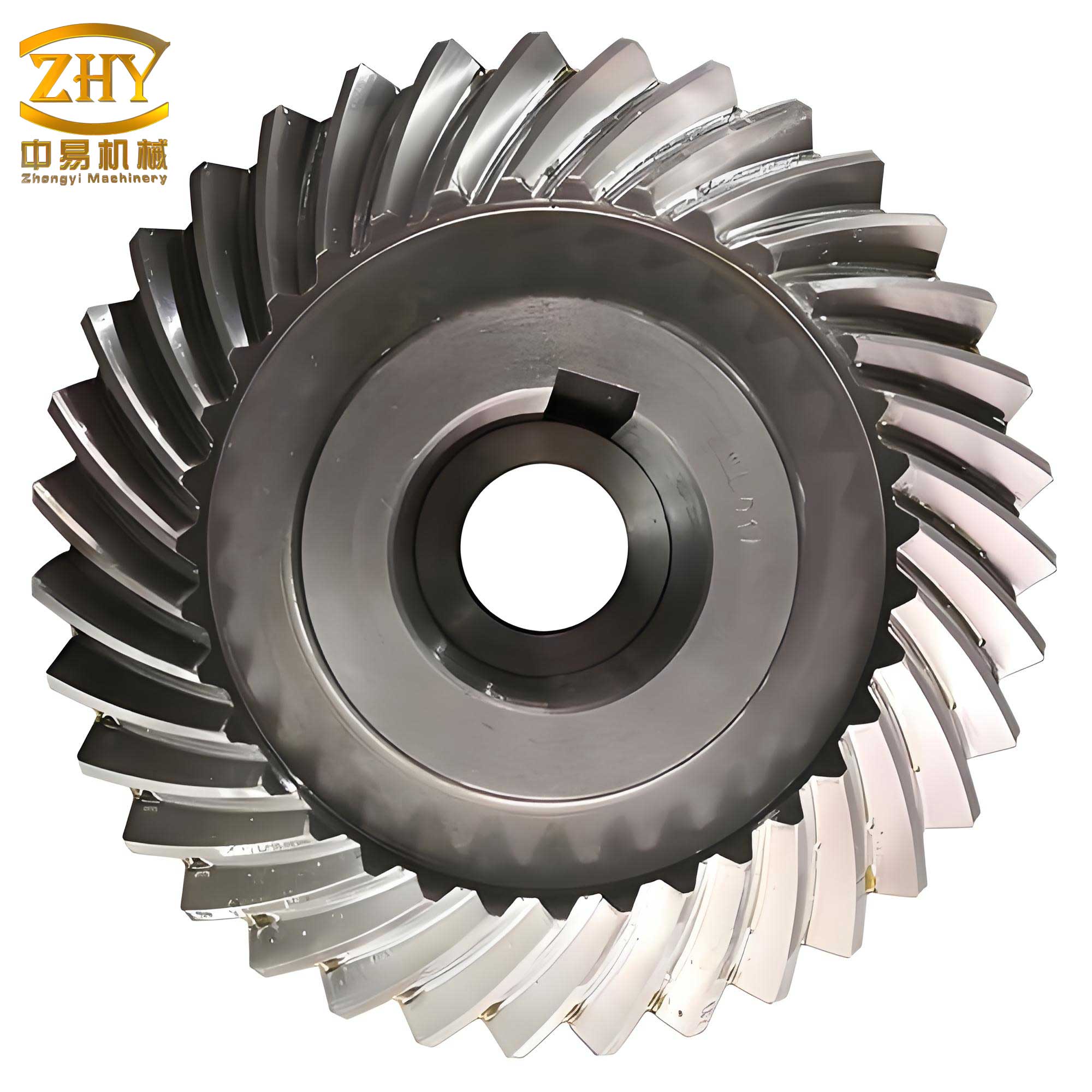
In my extensive experience with gear metrology, the study of contact traces in spiral gears has always been a fascinating and critical area. Spiral gears, specifically those with involute helicoid tooth surfaces, are fundamental components in crossed-axis transmissions. When two cylindrical helical gears mesh with non-parallel axes, this configuration is termed spiral gear meshing. A key characteristic of this meshing is that, at any given instant, the tooth surfaces of the two spiral gears contact at only a single point. The path traced by this contact point on a tooth surface during the transmission process is known as the contact trace, sometimes referred to as the normal engagement tooth profile. Understanding and measuring these contact traces is paramount, as they form the foundational啮合原理 for processes like gear hobbing, shaving, gear shaping, and worm wheel grinding. Furthermore, the error in the contact trace is an essential item in the error analysis of these gear manufacturing techniques and a primary inspection parameter within the tolerance system for involute spiral gear transmissions.
During the meshing transmission of spiral gears, the locus of the contact point in a stationary coordinate system fixed to the machine base is called the line of action. This line is simultaneously tangent to the base cylinders of both gears. The intersection points of the tooth surface with this line of action trace out the contact trace on the gear tooth. The orientation of the line of action within the tangent plane of the base cylinder is crucial for analysis.
Consider a coordinate system where the gear axis is the z-axis. A plane parallel to the tangent plane of the base cylinder is established, with the x-axis passing through the node point. When the gear rotates about the z-axis, the trajectory of the intersection point between the tooth surface and the line of action defines the contact trace. Since the line of action’s direction in the base cylinder tangent plane is fixed—determined solely by the base helix angle—the shape of the contact trace depends only on the base circle diameter $d_b$ and the base helix angle $\beta_b$ of the involute spiral gear. For a straight spur involute gear, the contact trace simplifies to the transverse involute curve. However, for spiral gears, it is a spatial curve on the helicoid surface.
The measurement of contact trace error is vital. When using a worm as a measuring element in a single-flank, intermittent meshing composite measurement, the motion error induced by contact trace error can be captured. Considering the direction of error transmission, the contact trace error should be measured along the direction of the line of action. While specialized instruments for单项测量 of contact traces are not yet common, the motion analysis provides a blueprint for such devices or for adapting existing coordinate measuring machines.
Kinematic Analysis for Contact Trace Measurement
From my analysis, a dedicated contact trace measuring instrument must execute four specific motions relative to the被测 spiral gear. Let’s establish a coordinate system attached to the gear: the z-axis coincides with the gear axis, the x-axis lies in the base cylinder tangent plane and passes through the starting measurement point, and the y-axis is perpendicular within that plane. The starting point on the contact trace is denoted as point $A$. After the gear rotates by an angle $\theta$, the tooth profile moves from position $A$ to $A’$, and the new contact point with the fixed line of action is point $B$.
The required motions are:
- Radial Adjustment Motion: This adjusts the measuring probe’s position relative to the gear along the x-direction to ensure it operates within the base cylinder tangent plane.
- Gear Rotation: The被测 spiral gear rotates about its z-axis by angle $\theta$.
- Probe Translation along X: As the gear rotates, the probe must move in the base tangent plane from point $A$ to point $B’$ (the projection related to the rotation) along the x-direction.
- Probe Translation along Z: A synchronized axial motion of the probe along the gear’s z-axis, from $B’$ to the actual contact point $B$, which is governed by a specific functional relationship with the gear’s rotation angle.
From geometric relationships, if $r_b$ is the base radius and $\beta_b$ is the base helix angle, the arc length unrolled from the base circle corresponding to rotation $\theta$ is $r_b \theta$. The components of motion can be derived. The movement $AB’$ corresponds to the developed length $r_b \theta$, and its projection in the x-direction is $r_b \theta \sin \beta_b$. The axial movement $B’B$ is $r_b \theta \tan \beta_b$. Therefore, the motion equations for an ideal contact trace measurement in this coordinate system are:
$$
x = r_b \theta \sin \beta_b \\
y = r_b \theta \cos \beta_b \\
z = r_b \theta \tan \beta_b
$$
Here, $(x, y, z)$ are the coordinates of the contact point $B$ in the defined system. Note that the y-motion is often related to the radial adjustment or can be set constant for a given measurement line. For practical measurement, the critical controlled motions are the gear rotation $\theta$, the probe horizontal movement (x), and the probe vertical/axial movement (z). On a computer-controlled three-coordinate measuring machine equipped with a rotary table, these equations can be directly programmed to perform contact trace measurement. For instruments based on mechanical generation, these equations guide the design of the传动机构.
Principles and Limitations of Contact Trace Measurement on Specific Gear Measuring Instruments
In my work, I have often explored using existing gear measuring instruments for contact trace evaluation. Consider a classic gear measuring instrument analogous to the one described in the source material. On such an instrument, when the rolling disk size does not equal the theoretical base circle size, the stylus tip relative to the tooth surface does not follow a transverse involute but rather a helical involute path. The central question becomes: for what rolling disk size does this helical involute path exactly coincide with the desired contact trace of the spiral gear? Furthermore, due to the instrument’s inherent motion constraints, what are the limiting conditions for performing valid contact trace measurements?
The instrument’s design involves a straight edge and a rolling disk. The horizontal movement of the straight edge is linked to the gear rotation, and the vertical movement of the measuring head is a fraction of this horizontal movement. Let the diameter of the rolling disk be $D$. When measuring a standard involute, $D$ is set equal to the base diameter $d_b$. For measuring the contact trace of a spiral gear, we need to find the required $D$.
From the motion equations, the required vertical (axial) movement of the probe is $z = r_b \theta \tan \beta_b$. The instrument is designed such that the probe’s vertical movement is half the horizontal movement of the straight edge. Let the horizontal movement of the straight edge be $S$. The gear rotation $\theta$ is related to $S$ and the disk radius $R=D/2$ by the rolling condition. For a pure rolling disk, the rotation angle $\theta$ of the gear/workpiece is related to the horizontal movement $S$ by $S = R \theta$. The probe’s vertical movement in the instrument is designed as $z_{inst} = S / 2 = R \theta / 2$.
For this to match the required axial motion $z = r_b \theta \tan \beta_b$, we set:
$$
\frac{R \theta}{2} = r_b \theta \tan \beta_b
$$
Canceling $\theta$ and substituting $R = D/2$ and $r_b = d_b/2$, we get:
$$
\frac{D}{4} = \frac{d_b}{2} \tan \beta_b \quad \Rightarrow \quad D = 2 d_b \tan \beta_b
$$
This equation $D = 2 d_b \tan \beta_b$ gives the rolling disk diameter required to measure the contact trace on this specific instrument.
However, we must verify the horizontal motion. The instrument’s horizontal补偿运动 for the probe, when set up for spiral gears, involves an adjustment angle $\beta_0$. From the instrument’s manual, $\beta_0$ is calculated as $\beta_0 = \arctan(\tan \beta / \cos \alpha_n)$, where $\beta$ is the分圆螺旋角 and $\alpha_n$ is the normal pressure angle. For the base helix angle $\beta_b$, the relationship is $\tan \beta_b = \tan \beta \cos \alpha_t$, where $\alpha_t$ is the transverse pressure angle. In many cases, especially for standard gears, $\beta_0$ approximates $\beta_b$. When $\beta_0 = \beta_b$, the total horizontal movement of the probe relative to the straight edge becomes $r_b \theta \sin \beta_b$, which matches the required x-motion from our kinematic equations. This confirms the validity of the derived disk size formula.
The instrument’s mechanics impose restrictions. The difference between the selected rolling disk diameter $D$ and the base diameter $d_b$ must be within the machine’s adjustment range. This leads to a constraint inequality. Furthermore, the fixed relationship between the straight edge movement direction and the probe’s vertical movement direction dictates that only specific spiral gear geometries can be measured. For instance, it may effectively limit measurement to contact traces on one hand of the spiral (e.g., right-hand螺旋齿轮).
From the condition that the disk size $D$ must be physically realizable and positive, and considering typical gear geometries where the分圆螺旋角 $\beta$ is usually less than 45°, we can derive the permissible range for the base helix angle $\beta_b$. The table below summarizes the approximate limiting conditions based on common instrument capabilities and the formula $D = 2 d_b \tan \beta_b$.
| Parameter | Condition | Typical Range for Feasibility |
|---|---|---|
| Base Helix Angle, $\beta_b$ | Must satisfy $D_{min} \leq 2 d_b \tan \beta_b \leq D_{max}$ where $D_{min}, D_{max}$ are instrument’s disk limits. | Approximately $5^\circ \leq \beta_b \leq 30^\circ$ for standard instrument configurations. |
| Gear Handedness | Instrument mechanics may favor one direction due to the fixed motion linkage. | Often limited to right-hand spiral gears for standard setup. |
| Base Circle Diameter, $d_b$ | Must be compatible with instrument’s center distance and disk size system. | Within the instrument’s specified workpiece size range. |
These limitations highlight that while adaptable, general-purpose gear measuring instruments may not be ideal for all spiral gear contact trace measurements. This underscores the need for specialized, computer-controlled systems that can freely execute the precise kinematic equations.
Advanced Considerations and Error Sources in Contact Trace Measurement
In my practice, ensuring accurate measurement involves careful consideration of several factors beyond the basic kinematics. The alignment of the measuring probe is critical. The sensor’s measuring force should be applied perpendicular to the instantaneous contact line (which is along the tooth surface normal at the contact point). This ensures that the sensor captures the error component precisely in the direction of the line of action, which is the defined direction for quantifying contact trace error. Misalignment can lead to cosine errors and inaccurate readings.
Furthermore, the definition of the “contact trace” itself can be nuanced. In perfect, rigid spiral gears, the theoretical contact is a point moving along a line on the tooth surface. However, under load, elastic deformation causes a contact ellipse. The measurement discussed here pertains to the geometric, unloaded contact trace. For loaded tooth contact analysis, different techniques are required.
The mathematical model can be extended. The fundamental equations derived assume the line of action is fixed in space. For a pair of spiral gears with specific shaft angle $\Sigma$ and center distance $a$, the orientation of the line of action relative to each gear’s coordinate system is determined by the base helix angles $\beta_{b1}$ and $\beta_{b2}$. The relationship is given by the law of gearing for crossed axes. The normal plane module $m_n$ and pressure angle $\alpha_n$ also play a role. A more comprehensive set of equations for the contact trace on gear 1, parameterized by the rotation angle $\theta_1$, could be expressed as:
$$
\begin{aligned}
x_1 &= r_{b1} \theta_1 \sin \beta_{b1} \\
y_1 &= r_{b1} \theta_1 \cos \beta_{b1} \\
z_1 &= r_{b1} \theta_1 \tan \beta_{b1}
\end{aligned}
$$
where $r_{b1}$ is the base radius of gear 1. For the mating gear 2, a similar set exists but is transformed via the shaft angle and center distance. This illustrates the symmetry and interdependence in spiral gear pairs.
When programming a CMM, additional corrections for probe tip radius compensation must be applied, as the measured point is the center of a spherical stylus, not the actual surface point. The compensation is performed along the surface normal, which for an involute helicoid is known from its geometry. The surface normal at a point on an involute helicoid is constant in the transverse section and has a fixed lead angle. The normal vector components can be derived from the base helix angle and the pressure angle.
Practical Application and Industry Relevance
The measurement of contact traces in spiral gears is not merely an academic exercise. It has direct implications for manufacturing quality control and process optimization. In gear grinding processes like worm wheel grinding, the contact trace between the grinding worm and the workpiece gear directly influences the final tooth form and lead modifications. By measuring the contact trace error on a finished gear, one can diagnose issues in the machine tool setup, such as incorrect wheel alignment, errors in the kinematic chain, or thermal distortions.
Similarly, in gear shaving, the contact pattern between the shaving cutter and the gear is crucial for achieving the desired surface finish and corrective shaping. A quantified measurement of the contact trace deviation from theoretical provides objective data for process adjustment.
With the advent of more powerful and affordable CNC systems, the direct implementation of the kinematic equations for contact trace measurement is becoming increasingly feasible. Modern gear measuring centers often incorporate rotary axes and sophisticated software that can be user-programmed for special tasks like this. The core requirement is a precise mathematical model of the spiral gear tooth surface, which for involute spiral gears is well-established.
The formula for the position vector of a point on a right-hand involute helicoid surface is given by:
$$
\begin{aligned}
\mathbf{r}(u, v) &= \begin{bmatrix}
r_b (\cos(u + v) + u \sin(u + v) \sin \beta_b) \\
r_b (\sin(u + v) – u \cos(u + v) \sin \beta_b) \\
r_b u \cos \beta_b
\end{bmatrix}
\end{aligned}
$$
where $u$ is the involute roll angle parameter and $v$ is the rotational parameter about the axis. The contact trace is a specific curve on this surface defined by the intersection with the plane representing the line of action. Solving this intersection yields the parametric equations we derived earlier, with $u$ proportional to $\theta$.
To facilitate quick reference for engineers, the key parameters influencing the contact trace of a spiral gear are summarized below.
| Symbol | Parameter | Role in Contact Trace Definition |
|---|---|---|
| $d_b$ | Base circle diameter | Scales the linear extent of the trace; $r_b = d_b/2$ is the proportionality factor in motion equations. |
| $\beta_b$ | Base helix angle | Determines the slope and spatial orientation of the trace. Defines the ratio between axial and transverse movements. |
| $\alpha_n$ | Normal pressure angle | Indirectly affects $\beta_b$ via the relationship $\tan \beta_b = \tan \beta \cos \alpha_t$. |
| $\beta$ | Reference circle helix angle | The standard manufacturing parameter; related to $\beta_b$ through transverse pressure angle. |
| $m_n$ | Normal module | Defines tooth size; influences base diameter $d_b = m_n z / \cos \beta \cdot \cos \alpha_t$. |
Repeatedly, we see that the geometry of spiral gears is central to this discussion. The螺旋齿轮 design dictates the unique challenges and solutions in metrology.
Future Directions and Conclusion
Looking ahead, the demand for precise measurement of complex gear geometries like spiral gears will only grow with advancements in electric vehicles, aerospace transmissions, and high-performance robotics. These applications often use spiral gears in crossed-axis configurations for compact, efficient power transfer. Therefore, developing more robust, universal, and automated methods for contact trace measurement is essential.
Potential future directions include the integration of optical scanning or laser line probes on multi-axis systems to capture the entire tooth surface point cloud. Advanced algorithms could then fit the theoretical involute helicoid model and extract the contact trace deviation directly. Machine learning techniques could be employed to correlate contact trace errors with specific manufacturing process faults.
In conclusion, based on my analysis and experience, the measurement of contact traces in involute spiral gears is a well-defined but practically nuanced task. It rests on a solid kinematic foundation expressed by the motion equations $x = r_b \theta \sin \beta_b$, $y = r_b \theta \cos \beta_b$, and $z = r_b \theta \tan \beta_b$. While specialized instruments are scarce, modern CNC coordinate measuring machines and gear measuring centers offer a flexible platform for implementing this measurement by direct programming. Existing mechanical gear testers can be adapted within certain limits dictated by their kinematic chains, primarily related to the base helix angle range. The accurate measurement of contact trace error provides invaluable data for refining manufacturing processes and ensuring the high-performance operation of螺旋齿轮 transmissions in demanding mechanical systems. The continued emphasis on螺旋齿轮 technology will drive further innovation in this specialized metrology field.