
The pursuit of higher power density in hydraulic systems has driven the development of pumps capable of operating under increasingly demanding conditions of speed and pressure. Among various pump architectures, external gear pumps are prized for their simplicity, robustness, and cost-effectiveness. However, conventional involute gear profiles suffer from inherent limitations such as flow pulsation and trapping phenomena, which become magnified at high operational parameters. This has led to the investigation of alternative tooth profiles. The double-circular-arc profile, particularly when applied to spiral gears, presents a compelling solution. Spiral gears with a double-circular-arc tooth form offer significantly reduced flow pulsation and the virtual elimination of trapped volume, making them inherently more suitable for high-speed, high-pressure applications. The smooth meshing action of spiral gears contributes to lower noise and vibration levels, enhancing their performance profile.
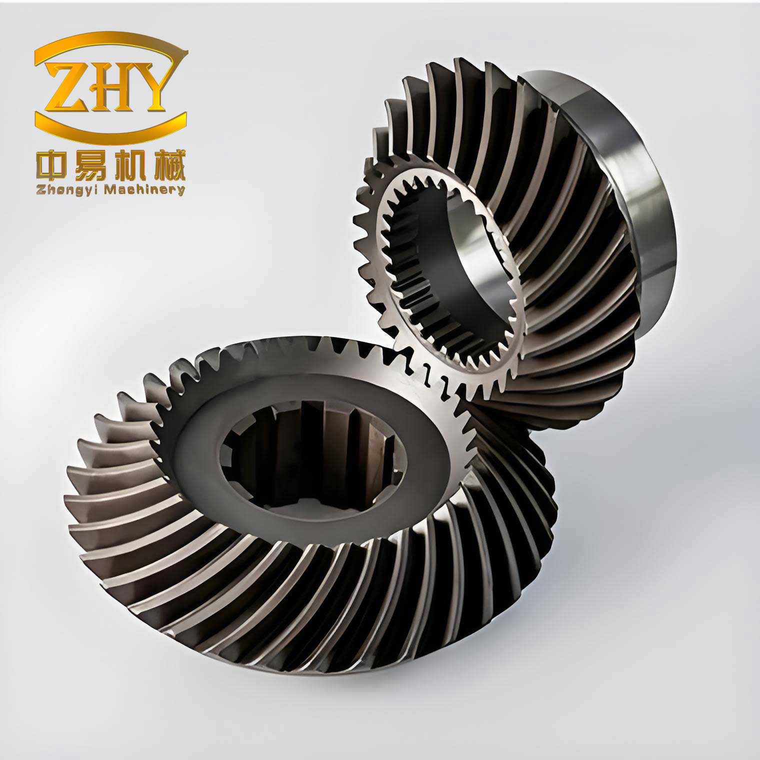
Despite the advantages offered by the double-circular-arc spiral gear design, its performance at extremes is critically governed by the management of internal clearances. In any gear pump, leakage paths exist primarily at the axial (side) clearance between the gear faces and the pump housing, and the radial (tip) clearance between the gear tooth tips and the pump casing. While axial clearance leakage often constitutes the majority of total leakage, the role of radial tip clearance cannot be disregarded, especially as it influences not only volumetric efficiency but also dynamic phenomena within the pump. At high pressures, the pressure differential across the “pressure building” chambers of the pump creates a strong driving force for leakage through the tip clearance. Concurrently, high rotational speeds can induce cavitation in the suction and meshing zones, a phenomenon where local pressure drops below the fluid’s vapor pressure, causing the formation and subsequent collapse of vapor bubbles. This cavitation can erode components, generate noise, and detrimentally affect the pump’s output flow characteristics. Intriguingly, the tip clearance and cavitation are not independent issues; the size of the clearance can influence the intensity and distribution of cavitation, and conversely, the presence of cavitating vapor in the clearance can act as a two-phase fluid seal, momentarily reducing leakage. Therefore, for spiral gear pumps destined for high-duty cycles, determining an optimal tip clearance that balances leakage losses against other dynamic losses and cavitation effects is paramount. This study focuses on establishing a mathematical model to define this optimal tip clearance for a high-pressure, high-speed double-circular-arc spiral gear pump and investigates the intricate interplay between tip clearance, leakage, and cavitation through detailed numerical analysis.
The core of the theoretical approach lies in modeling the total power loss associated with the tip clearance and minimizing it. The power loss ($\Delta N_j$) across the tip clearance of a spiral gear pump is a composite of three main components: the power loss due to the leakage flow itself ($\Delta N_{Qr}$), the power loss from fluid compression in the clearance ($\Delta N_t$), and the viscous friction loss ($\Delta N_{\delta}$) as the fluid shears within the narrow gap. The total power loss can be expressed as:
$$
\Delta N_j = \Delta N_{Qr} + \Delta N_t + \Delta N_{\delta}
$$
To accurately model the leakage flow ($Q_r$), one must account for real-world deformations. Under high pressure, both the gear shafts and the pump housing experience elastic deformation. The gear shaft deflects due to unbalanced radial forces, effectively increasing the average tip clearance. The pump housing deforms non-uniformly due to fluid pressure and bearing reaction forces, creating a circumferentially varying clearance. A refined leakage model integrating these deformations for spiral gears is developed. The pressure-driven (Poiseuille) and shear-driven (Couette) flow components are considered across the effective deformed clearance. The leakage flow rate can be modeled as:
$$
Q_r = \frac{\Delta p \cdot \delta_{eff}^3 \cdot D}{12 \mu L} – \frac{1}{2} \omega R_a \cdot \delta_{eff} \cdot D
$$
Where $\Delta p$ is the pressure difference, $\mu$ is the dynamic viscosity, $D$ is the effective sealing length along the spiral gear tip, $L$ is the land width (often simplified for this context), $\omega$ is the angular velocity, $R_a$ is the tip radius, and $\delta_{eff}$ is the effective clearance incorporating deformations. For a spiral gear, the geometry factor $D$ is influenced by the helix angle $\beta$. Combining the deformation effects—a constant shaft deflection $\delta_s$ and a housing deformation approximated as a function of angular position $\theta$—the effective clearance for power loss calculation is synthesized. The power loss due to this leakage is simply $\Delta N_{Qr} = \Delta p \cdot Q_r$.
The compression loss $\Delta N_t$ accounts for the work done to re-compress the fluid that has expanded into the clearance and is pushed back. The viscous friction loss $\Delta N_{\delta}$ is derived from the shear stress on the gear tips. The total power loss function $\Delta N_j(\delta)$ thus becomes a function of the nominal design tip clearance $\delta$. By taking the derivative of this function with respect to $\delta$ and setting it to zero, the optimal nominal clearance $\delta^*$ that minimizes total power loss can be solved for. For the specific spiral gear pump parameters in this study (operating at 25 MPa and 10,000 rpm), this theoretical minimization yields an optimal design tip clearance of:
$$
\delta^* \approx 0.0207 \text{ mm}
$$
To validate this theoretical finding and explore the underlying fluid dynamics, a comprehensive numerical simulation study was undertaken. Three-dimensional internal flow field models of the double-circular-arc spiral gear pump were created for three distinct nominal tip clearances: 0.01 mm, 0.02 mm, and 0.03 mm. The fluid domain was meshed using a dedicated template for rotary equipment, which accurately resolves the critical clearances with layered grids. The simulations were configured for transient analysis under the target operating conditions (10,000 rpm, 0.1 MPa inlet, 25 MPa outlet). A cavitation model was activated to capture the formation and transport of vapor, and a turbulence model was employed to resolve the complex flow structures. This setup allows for the direct observation of how the tip clearance dimension influences the internal flow field, particularly the cavitation patterns and leakage velocities.
The simulation results revealed a complex and interdependent relationship between tip clearance, cavitation intensity, and leakage flow. The table below summarizes the key performance indicators extracted from the stabilized operation of the pump with different clearances:
| Tip Clearance (mm) | Avg. Outlet Flow (L/min) | Flow Pulsation Rate (%) | Pressure Pulsation Rate (%) | Dominant Phenomenon |
|---|---|---|---|---|
| 0.01 | 42.50 | 35.55 | 5.48 | Severe Cavitation |
| 0.02 | 44.15 | 21.77 | 2.55 | Moderate Cavitation & Sealing |
| 0.03 | 42.16 | 24.38 | 0.78 | Significant Leakage |
The visualizations of the flow field provided profound insights. For the smallest clearance (0.01 mm), extensive cavitation clouds were observed in the suction region, tooth engagement zones, and remarkably, within the tip clearance passages themselves. This intense cavitation severely disrupted the pressure field, leading to the highest levels of flow and pressure pulsation, as reflected in the table. The average flow output was compromised. For the largest clearance (0.03 mm), cavitation was significantly suppressed, resulting in the smoothest pressure output (lowest pulsation). However, the absence of a two-phase vapor seal in the now-larger gap allowed substantial leakage flow from the high-pressure to low-pressure chambers, directly reducing the volumetric efficiency and average output flow.
The case with the 0.02 mm clearance presented the most balanced performance. Cavitation was present but less severe than in the 0.01 mm case. Crucially, the simulation indicated that the cavitating vapor within the tip clearance zone acted as a partial seal, impeding the leakage flow. This effect, combined with the inherently smaller gap, resulted in the lowest leakage among the three scenarios. Consequently, this configuration delivered the highest average flow rate. Furthermore, the flow and pressure pulsations were significantly lower than the 0.01 mm case, indicating better output quality. This optimal point, where the detrimental effects of cavitation and leakage are jointly minimized, aligns remarkably well with the theoretically predicted optimal clearance of 0.0207 mm.
The relationship can be summarized through the following key equations and conclusions. The leakage $Q_r$ increases with the cube of the effective clearance, while cavitation intensity generally decreases with increasing clearance due to reduced flow velocities and altered pressure gradients:
$$
Q_r \propto \delta_{eff}^3 \quad \text{and} \quad I_{cav} \propto f(\delta_{eff}^{-1})
$$
where $I_{cav}$ represents cavitation intensity. The net effect on pump flow output $Q_{out}$ is a superposition of theoretical displacement $Q_{th}$, leakage loss $Q_r$, and a cavitation-induced flow reduction factor $\eta_{cav}$:
$$
Q_{out} = Q_{th} \cdot \eta_{cav}(\delta) – Q_r(\delta)
$$
The optimal clearance $\delta^*$ for spiral gear pumps is found where the derivative of this output with respect to clearance is zero, considering the opposing trends of $\eta_{cav}$ and $Q_r$. In essence, there exists a “sweet spot” where the sealing benefit from mild cavitation in the tip clearance of the spiral gear outweighs its negative impact, and the clearance is still small enough to limit viscous shear and pressure-driven leakage.
In conclusion, this investigation underscores the critical importance of precisely engineered tip clearances in high-performance double-circular-arc spiral gear pumps. The study successfully developed a power-loss minimization model that accounts for deformations and dynamic losses, pinpointing an optimal design clearance. Numerical simulations validated this finding, demonstrating that the clearance which yields the best flow output and quality is not the smallest possible, but rather one that strategically balances competing fluid dynamic phenomena. The discovery that cavitation within the tip clearance of spiral gears can have a non-detrimental, even beneficial, sealing effect is a significant insight for pump designers. It highlights that complete avoidance of cavitation may not be the optimal design goal; instead, managing its extent and location is key. For the specific spiral gear pump analyzed, a tip clearance near 0.02 mm provides this optimal balance, maximizing volumetric efficiency and output stability under severe operating conditions. This methodology and the underlying principles provide a valuable framework for the design and optimization of advanced spiral gear pumps, enabling them to meet the escalating demands of modern high-pressure hydraulic systems.