
In my extensive experience with agricultural machinery maintenance, I have frequently encountered issues related to the premature failure of bevel gears in tractor central drive systems. These bevel gears are critical components, responsible for reducing rotational speed, increasing torque, and altering the direction of power transmission. When these bevel gears suffer early damage, it leads to operational degradation, abnormal noises, overheating, and oil leaks, significantly impacting tractor performance and longevity. This article delves into the root causes of such premature wear and failure of bevel gears, and provides comprehensive preventive strategies, incorporating tables and formulas to encapsulate key concepts. Throughout this discussion, the term ‘bevel gear’ will be emphasized to underscore its centrality.
The central drive system, housing the bevel gear pair, is subjected to substantial mechanical stresses during agricultural operations. The smaller bevel gear (pinion) typically has fewer teeth, while the larger bevel gear (crown wheel) has more, leading to differential wear rates. For instance, in many tractors, the pinion’s concave surface and the crown wheel’s convex surface engage under load, with the pinion rotating multiple times per single rotation of the crown wheel. This inherent motion predisposes the bevel gears to specific wear patterns, such as pitting and spalling, rather than outright tooth breakage. Understanding the multifaceted reasons behind early bevel gear damage is paramount for effective maintenance.
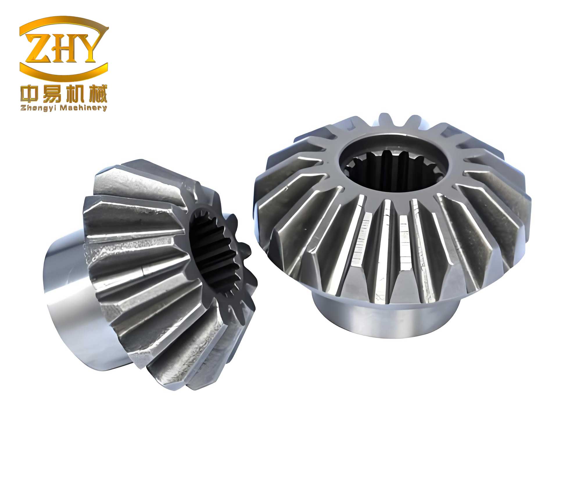
One of the primary culprits behind premature bevel gear failure is inadequate lubrication. Lubrication ensures a protective film between the meshing teeth of the bevel gear, preventing direct metal-to-metal contact. When this film is compromised, semi-dry or abrasive friction occurs, accelerating wear. The factors contributing to lubrication failure are multifaceted. First, the quality of the gear oil is crucial. Using an incorrect or substandard oil grade can lead to insufficient film strength. The selection of gear oil depends on the bevel gear type, load intensity, and sliding velocity. The American Petroleum Institute (API) service classifications, such as GL-3, GL-4, and GL-5, guide this choice. Furthermore, the oil’s viscosity grade must suit the operational temperature range. A common formula to estimate the required minimum film thickness $h_{min}$ between bevel gear teeth is derived from the Elastohydrodynamic Lubrication (EHL) theory:
$$h_{min} \approx 2.65 \frac{(U \eta_0)^{0.7} R^{0.43}}{\alpha^{0.54} E’^{0.03} W^{0.13}}$$
where $U$ is the rolling speed, $\eta_0$ is the dynamic viscosity at atmospheric pressure, $R$ is the effective radius of curvature, $\alpha$ is the pressure-viscosity coefficient, $E’$ is the effective elastic modulus, and $W$ is the load per unit width. If the actual film thickness falls below the composite surface roughness, wear intensifies.
| Bevel Gear Application | Load Condition | Recommended API Class | Typical Viscosity Grade (SAE) |
|---|---|---|---|
| Moderate-duty tractor central drive | Medium to High | GL-4 | 85W-90 |
| Heavy-duty or high-slip conditions | Very High | GL-5 | 85W-140 |
| Cold climate operations | Variable | GL-4 or GL-5 | 75W-90 |
Second, oil contamination is a silent destroyer of bevel gears. Abrasive particles act as grinding agents, causing three-body abrasion. The wear volume $V$ due to abrasion can be modeled by:
$$V = K \frac{W L}{H}$$
where $K$ is a wear coefficient, $W$ is the normal load, $L$ is the sliding distance, and $H$ is the material hardness. Regular oil changes and stringent cleanliness during assembly and maintenance are non-negotiable. Third, insufficient oil level leads to starvation, causing localized overheating and scuffing on the bevel gear surfaces. I always recommend establishing a strict regimen for checking oil levels and inspecting for leaks at seals, gaskets, and drain plugs.
Improper installation and maladjustment constitute another major cause of early bevel gear demise. The precise alignment and backlash setting between the pinion and crown wheel bevel gears are critical. When bearings, such as the pinion front bearing (e.g., 700409) or the differential carrier bearings (e.g., analogs of 7612, 7312), wear out without timely adjustment, excessive axial play develops. This play disrupts the designed contact pattern, leading to edge loading (toe or heel contact) on the bevel gear teeth. The resulting stress concentration dramatically reduces fatigue life. The basic relationship for bending stress at the tooth root of a bevel gear, based on the Lewis formula adapted for bevel gears, is:
$$\sigma_b = \frac{W_t}{F m_n Y} K_v K_o K_m$$
where $W_t$ is the tangential load, $F$ is the face width, $m_n$ is the normal module, $Y$ is the Lewis form factor, $K_v$ is the dynamic factor, $K_o$ is the overload factor, and $K_m$ is the load distribution factor. Misalignment increases $K_m$ and $K_o$, elevating $\sigma_b$ beyond safe limits. The prescribed axial play for the differential shaft is typically between 0.15 mm and 0.30 mm. Exceeding this range due to worn bearings or loose adjusting bolts allows the bevel gear pair to operate with excessive backlash, subjecting it to impact loads during torque reversals.
| Fault | Direct Consequence | Effect on Bevel Gear | Corrective Action |
|---|---|---|---|
| Excessive pinion bearing (2712K) radial clearance | Pinion wobble and misalignment | Irregular contact pattern, increased pitting | Replace bearing, reset pinion depth |
| Worn differential carrier bearings | Increased crown wheel axial play | Increased backlash, tooth impact, spalling | Adjust bearing preload or replace |
| Loose transmission-to-housing bolts | Relative misalignment of gear axes | Localized high-contact stress on bevel gear teeth | Torque bolts to specification, check pattern |
| Incorrect pinion depth setting after bearing replacement | Altered gear mesh center | Toe or heel contact, rapid surface fatigue | Always perform full gear pattern check and adjustment |
Operational practices play a significant role in the lifespan of bevel gears. In my observations, certain driving habits accelerate wear. For example, consistent use of a single turning direction during plowing (e.g., always turning right) places asymmetrical loads on the differential bearings. This uneven wear eventually alters the bevel gear mesh. Similarly, “shock loading” from abrupt clutch engagement or harsh braking imposes transient torque peaks far exceeding the design capacity of the bevel gear teeth. The dynamic load $W_{dyn}$ can be estimated as:
$$W_{dyn} = W_t \cdot K_v \approx W_t \left(1 + \frac{v}{C}\right)$$
for moderate speeds, where $v$ is the pitch line velocity and $C$ is a constant. Shock loads cause a spike in $K_v$, leading to plastic deformation or micro-cracking at the tooth surface. Furthermore, small field operations with frequent turning, or constant high-speed travel, increase the cyclic stress frequency on the bevel gear, potentially reducing the time to fatigue-induced pitting according to the S-N curve relationship:
$$N S^m = C$$
where $N$ is the number of cycles to failure, $S$ is the stress amplitude, and $m$ and $C$ are material constants.
The integrity of surrounding structural components is often overlooked. The tractor’s main frame or the axle housing supports that hold the bevel gear assembly can deform or crack due to overloading or impact. Such deformation misaligns the entire central drive, forcing the bevel gears to operate under severe bias. The induced misalignment angle $\theta$ can generate an additional bending moment $M$ on the pinion shaft:
$$M = F_t \cdot e \cdot \sin(\theta)$$
where $F_t$ is the tangential force and $e$ is an offset distance. This moment increases bearing loads and tooth misalignment. Regular inspection of the chassis and mounting points is essential to ensure a stable platform for the bevel gear set.
A particularly avoidable cause of premature failure is the neglect of readjustment after component replacement. Whenever a critical component like the pinion front bearing is replaced, the entire geometry of the bevel gear mesh shifts. Failure to recalibrate the pinion depth, crown wheel position, backlash, and contact pattern guarantees that the bevel gears will run under suboptimal conditions. The backlash $j$ is a critical parameter, often set between 0.20 mm and 0.35 mm, and is related to the axial adjustments of the gears. The relationship can be simplified as:
$$j \approx 2 \Delta A \tan(\alpha)$$
where $\Delta A$ is the change in axial position and $\alpha$ is the pressure angle of the bevel gear. Ignoring this adjustment after service is a direct path to accelerated bevel gear wear.
Based on these causes, I propose a systematic set of preventive measures. For lubrication, adhere to a strict oil quality and change schedule. Use magnetic drain plugs to capture ferrous wear debris from the bevel gear set. Implement particle counting or oil analysis to monitor contamination. For installation, develop a meticulous procedure using dial indicators to set bearing preloads and gear backlash. Always verify the contact pattern using Prussian blue or marking compound. The ideal pattern should be centered on the tooth flank, avoiding the edges. A sample calculation for required shim thickness $S$ to set pinion depth can be based on the manufacturer’s specification and measured assembly dimensions:
$$S = D_{spec} – (M_{measured} + C_{constant})$$
where $D_{spec}$ is the specified pinion depth, $M_{measured}$ is a measurement from a dummy pinion, and $C$ is a tooling constant.
| Maintenance Activity | Frequency | Key Parameters to Check/Adjust | Tools/Equipment Needed |
|---|---|---|---|
| Oil level and condition inspection | Every 50 operating hours | Oil level, visual contamination | Dipstick, sight glass |
| Gear oil change | Every 500-1000 hours (per OEM) | Replace with specified oil grade | Drain pan, funnel, torque wrench |
| Backlash and pattern check | Every 1000 hours or after shock load event | Backlash (0.20-0.35 mm), contact pattern on bevel gear teeth | Dial indicator, marking compound |
| Bearing preload/axial play check | Every 2000 hours | Differential shaft axial play (0.15-0.30 mm) | Pry bar, dial indicator |
| Structural bolt torque check | Every 500 hours | Transmission-housing bolts, differential carrier bolts | Torque wrench |
Operator training is vital. Educate drivers on smooth clutch operation, avoiding aggressive braking, and alternating turning directions during field work to distribute bearing wear evenly. For structural issues, incorporate frame and mounting inspections into major service intervals. Finally, enforce a mandatory readjustment protocol after any repair involving the central drive components. This includes not only bevel gear replacement but also bearing, seal, or housing work that could disturb the aligned positions.
In conclusion, the early damage of bevel gears in tractor central drives is a multifaceted problem rooted in lubrication, adjustment, operation, structural integrity, and maintenance discipline. Each factor interrelates, and negligence in one area can precipitate failure. By understanding the underlying mechanisms—quantifiable through wear formulas and stress analyses—and implementing a rigorous, data-driven maintenance regimen summarized in tables, the service life of these critical bevel gears can be extended significantly. The bevel gear is the heart of the central drive, and its protection demands consistent attention to detail, proper lubrication, precise adjustment, and sensible operation. Through these measures, the undesirable consequences of noise, heat, and leakage can be effectively mitigated, ensuring reliable tractor performance.