
This article provides an in-depth analysis of a recurring failure mode observed in the central drive bevel gears of a specific aero-engine model. Following a logical, top-down approach, we construct a detailed fault tree to systematically enumerate and evaluate all potential root causes for the observed tooth surface damage. The analysis conclusively identifies an insufficient specified interference fit between the drive bevel gear bearing housing and the accessory gearbox bore as the primary causative factor. Detailed engineering calculations supporting this conclusion are presented, along with comprehensive design, manufacturing, and maintenance countermeasures to prevent recurrence.
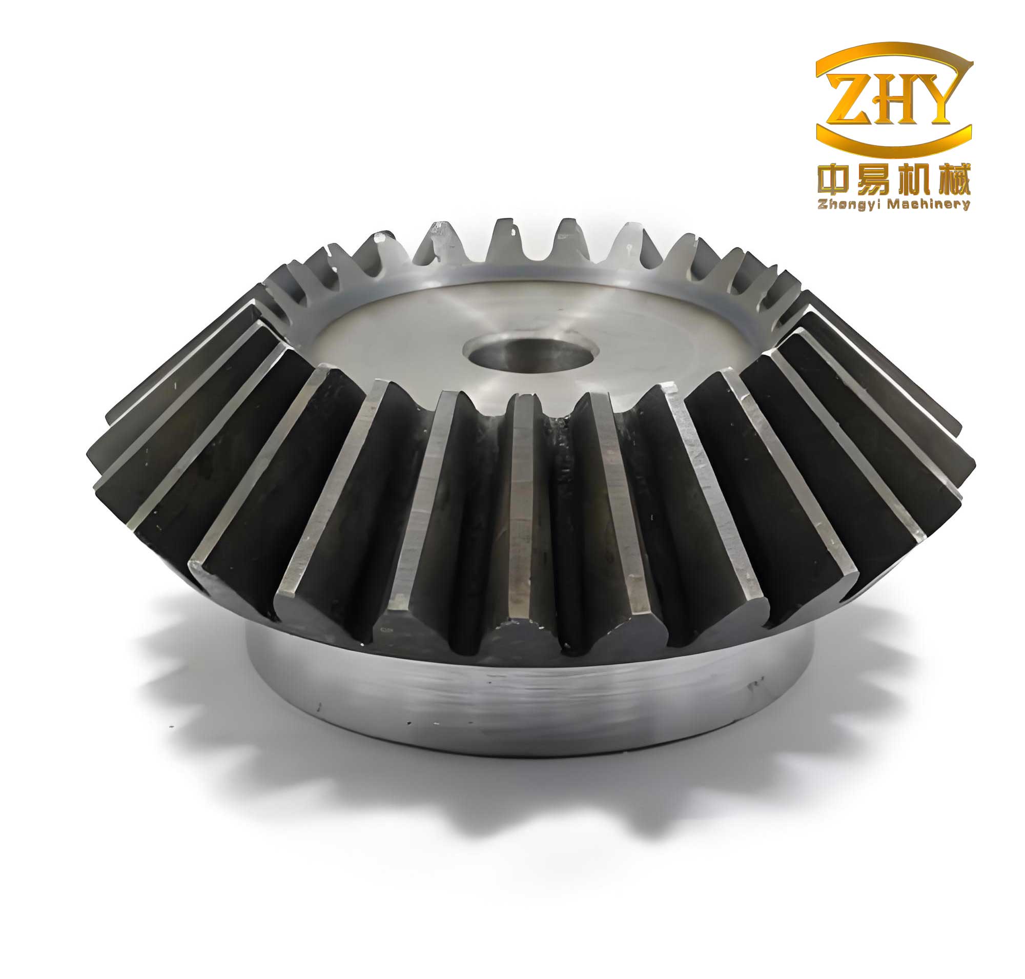
Central drive bevel gears are critical components within aero-engine accessory gearboxes. Their primary function is to transfer power from the engine’s core (typically the compressor) to the various aircraft and engine accessories, simultaneously altering the direction of the power transmission. The integrity of these bevel gears is paramount for the entire accessory drive train. A failure can disrupt essential systems and, in severe cases, lead to an engine shutdown. These components operate at high rotational speeds and are subjected to complex cyclic stresses including tension, compression, sliding-shear, rolling, and rolling-sliding contact. Consequently, they demand exceptionally high standards of manufacturing precision, material quality, and installation accuracy. The production process for such high-performance bevel gears involves multiple stages: rough machining, gear cutting (hobbing, milling), heat treatment, deburring, and finally, a meticulous pairing process. Installation must guarantee precise meshing geometry and contact pattern alignment to ensure smooth transmission, operational reliability, and flight safety.
1. Failure Case Description
During the overhaul of a specific aero-engine model, an alarming scrappage rate of over 55% was observed for the central drive bevel gear sets, leading to significantly increased maintenance costs, extended turnaround times, and heightened flight safety concerns.
Post-test cell teardown inspections revealed severe damage. The drive (pinion) bevel gear exhibited pronounced wear and spalling across the convex side of all teeth. The driven (gear) bevel gear showed matching severe wear and spalling on the concave side of all teeth, specifically around the pitch line, exposing the base material. Evidence of adhesive wear (smearing) was present at the toe (small end) of some teeth.
Further investigation uncovered additional collateral damage: the four nuts and lock plates securing the drive bevel gear bearing housing were found loose. The internal bore of the bearing housing, which interfaces with the bearing outer race, displayed severe wear tracks with localized depths up to 0.14 mm. Upon removal, the outer diameter of the bearing housing itself showed wear marks. Corresponding wear was found on the bore wall and face of the accessory gearbox mounting location. The supporting ball bearing for the drive pinion was also damaged, with wear on the raceways and severe degradation of the cage. This cascade of failures rendered both bevel gears in the set irreparable. This failure was not isolated, as two other engines of the same model subsequently exhibited identical tooth surface damage patterns following bench testing.
2. Fault Mechanism Analysis for Bevel Gears
To rigorously identify the root cause of the tooth surface damage, we employ a Fault Tree Analysis (FTA) methodology. The top event is defined as “Tooth Surface Damage on Central Drive Bevel Gears.” We then logically decompose this event into its immediate, necessary, and sufficient causes, progressing through successive levels of detail. The analysis explores six primary branches: High Operational Loads, Inherent Design Flaws, Manufacturing Errors, Installation/Assembly Errors, Misalignment/Uneven Load Distribution, and Lubrication Deficiencies. The resulting fault tree structure provides a comprehensive map of potential failure paths, as summarized in the following table which categorizes the major contributing factors.
| Primary Category | Specific Sub-factors | Potential Effect on Bevel Gears |
|---|---|---|
| Design & Analysis | Insufficient interference fit; Low support stiffness; Inadequate contact pattern design; Incorrect material selection. | Altered meshing position, increased backlash, dynamic instability, localized high contact stress. |
| Manufacturing & Quality | Base pitch error; Profile error; Pitch error; Eccentricity; Heat treatment defects; Surface finish issues. | Poor meshing quality, increased vibration and noise, dynamic load amplification, stress concentrations. |
| Assembly & Installation | Incorrect mounting distance; Excessive/Insufficient backlash; Poor contact pattern; Bearing preload error; Housing bore misalignment. | Edge loading, biased tooth contact, altered load distribution, increased sliding action. |
| Operational & Environmental | High speed/load cycles; Lubricant starvation/viscosity breakdown; Contamination (water, debris); Extreme operating temperatures. | Breakdown of elastohydrodynamic (EHL) film, scuffing, micropitting, accelerated wear, thermal distress. |
2.1 Analysis of Operational Loads
The operational conditions for these bevel gears are demanding. Calculations based on the engine’s gear train ratios indicate the following speeds:
- Drive (Pinion) Bevel Gear: ~5930 rpm (operational), ~2372 rpm (during engine start).
- Driven (Gear) Bevel Gear: ~5660 rpm (operational), ~2264 rpm (during engine start).
The key geometric parameters of the bevel gear pair are listed below:
| Parameter | Drive (Pinion) Bevel Gear | Driven (Gear) Bevel Gear |
|---|---|---|
| Number of Teeth, $z$ | 21 | 22 |
| Module (at large end), $m_n$ (mm) | 4 | 4 |
| Normal Pressure Angle, $\alpha_n$ | 20° | 20° |
| Pitch Cone Angle, $\delta$ | 43.7° | 46.3° |
| Hand of Spiral | Right Hand | Left Hand |
| Pitch Diameter, $d$ (mm) | 84 | 88 |
A bevel gear tooth is subjected to three mutually perpendicular force components: tangential ($F_t$), radial ($F_r$), and axial ($F_a$). The starting condition is often the most critical from a load perspective. The forces can be calculated as follows, assuming a spiral angle $\beta = 0$ (straight bevel gear for simplification in this case):
Starting Torque: $$ T = 9550 \times \frac{P}{n} $$ where $P$ is the starting power (kW) and $n$ is the starting speed (rpm).
Tangential Force: $$ F_t = \frac{2000 \cdot T}{d_m} $$ where $d_m$ is the mean pitch diameter.
Radial Force (on pinion): $$ F_r = \frac{F_t}{\cos \beta} (\tan \alpha_n \cos \delta_1 + \sin \beta \sin \delta_1) $$ For $\beta=0$, this simplifies to: $$ F_r = F_t \tan \alpha_n \cos \delta_1 $$
Axial Force (on pinion): $$ F_a = \frac{F_t}{\cos \beta} (\tan \alpha_n \sin \delta_1 – \sin \beta \cos \delta_1) $$ For $\beta=0$, this simplifies to: $$ F_a = F_t \tan \alpha_n \sin \delta_1 $$
Using the relevant engine parameters for the start cycle, the calculated loads are significant:
$$ T \approx 96.6 \text{ N·m}, \quad F_t \approx 2300 \text{ N}, \quad F_r \approx F_a \approx 575 \text{ N} $$
These high transient loads, combined with high speed, certainly contribute to the demanding operating environment of the bevel gears and are a necessary condition for the observed high-stress contact fatigue.
2.2 In-depth Analysis of Design and Assembly Factors
While high loads are a contributing factor, the investigation must focus on why this specific gear set failed repeatedly when others under similar conditions may not. The fault tree leads us to examine design and assembly intricacies.
2.2.1 Critical Issue: Insufficient Specified Interference Fit
The most critical finding relates to the fitted connection between the drive bevel gear’s bearing housing and the accessory gearbox. The accessory gearbox casing is manufactured from ZM-5 magnesium alloy, which has a coefficient of thermal expansion (CTE), $\alpha_{Mg}$, of approximately $23 \times 10^{-6} \, \text{°C}^{-1}$. The bearing housing is made from 12CrNi3A steel, with a CTE, $\alpha_{St}$, of approximately $11.5 \times 10^{-6} \, \text{°C}^{-1}$. The nominal diameter at the fit, $\phi_d$, is 82 mm. The operational oil temperature is around $100\text{°C}$, giving a temperature rise, $\Delta t$, of about $80\text{°C}$ from ambient ($20\text{°C}$).
The thermal expansion of a diameter is calculated by:
$$ \Delta d = \Delta t \times \alpha \times \phi_d $$
Applying this formula:
- Accessory Gearbox Bore Expansion: $\Delta d_{bore} = 80 \times (23 \times 10^{-6}) \times 82 \approx 0.151 \text{ mm}$
- Bearing Housing OD Expansion: $\Delta d_{housing} = 80 \times (11.5 \times 10^{-6}) \times 82 \approx 0.075 \text{ mm}$
The net change in the fit at operating temperature is the difference: $\Delta d_{bore} – \Delta d_{housing} \approx 0.076 \text{ mm}$. This means the bore expands more than the housing, effectively reducing any initial interference or increasing any initial clearance by this amount.
The specified interference fit for this engine was a maximum of $0.045$ mm. Analysis of a foreign counterpart engine for the same role revealed a specified interference range of $0.093$ mm to $0.113$ mm.
This discrepancy is pivotal. Even if the maximum specified interference of $0.045$ mm was achieved during cold assembly, the thermal expansion effect would completely negate it and create a clearance fit at operating temperature:
$$ \text{Effective Clearance at Operation} = (0.045 \text{ mm initial interference}) – (0.076 \text{ mm expansion loss}) = -0.031 \text{ mm clearance} $$
| Condition | Bore Diameter (mm) | Housing OD (mm) | Fit Status | Consequence for Bevel Gears |
|---|---|---|---|---|
| Ambient (Assembled) | $\phi_{d,bore}$ | $\phi_{d,housing} = \phi_{d,bore} – 0.045$ | Designed Interference (Max) | Proper alignment, rigid support. |
| Operating (Hot) | $\phi_{d,bore} + 0.151$ | $(\phi_{d,bore} – 0.045) + 0.075$ | ~0.031 mm Clearance | Housing can vibrate/move, support lost. |
This transition from an interference to a clearance fit has catastrophic consequences for the bevel gears:
- Micro-Motion and Fretting: Under cyclical loads, the bearing housing can experience small-amplitude radial vibration (fretting) within the now-oversized bore.
- Loss of Preload and Bearing Alignment: This motion works against the preload provided by the mounting nuts, eventually causing them to loosen. Once loose, axial clamping is lost, allowing the housing to tilt and “settle” into the bore under load.
- Displacement of Gear Meshing Geometry: The settling and tilting of the housing causes the entire drive pinion assembly (bearing and gear) to displace radially and axially. This alters the critical mounting distance, shaft angle, and center distance of the bevel gear pair.
- Destructive Contact Pattern Shift: The altered geometry shifts the tooth contact pattern towards the heel (large end) of the bevel gears. Load becomes concentrated on a smaller area, dramatically increasing contact stress ($\sigma_H$), which is governed by formulas like the AGMA contact stress equation for bevel gears:
$$ \sigma_H = Z_E \sqrt{\frac{F_t}{d_m b} \cdot \frac{u+1}{u} \cdot Z_I \cdot K_O K_V K_{H\beta} K_{H\alpha}} $$
where factors like the face load distribution factor $K_{H\beta}$ increase severely with misalignment, leading to spalling. - Vicious Cycle of Degradation: The spalling damage on the bevel gears increases transmission error and vibrations. These increased dynamics further accelerate the wear in the loose bearing housing interface and degrade the bearing itself. The degraded bearing develops increased internal clearance, which further worsens the pinion’s positional stability, creating a positive feedback loop of escalating damage until catastrophic failure.
2.2.2 Secondary Factor: Drive Pinion Support Stiffness
The drive pinion in this design is a relatively long, slender shaft supported at one end by a spline connection (providing radial but limited axial constraint) and at the other end by a single ball bearing. This configuration can have relatively low lateral and torsional stiffness. Under the significant axial load component ($F_a$), the pinion can experience axial deflection. This changes the operating backlash and, more critically, the contact pattern along the face width. Fluctuations between start and cruise conditions can cause the contact pattern to “walk,” leading to characteristic butterfly-shaped wear patterns and exacerbating surface fatigue.
2.3 Other Contributing Factors from the Fault Tree
While the insufficient interference fit is primary, other branches of the fault tree represent necessary checks and potential aggravating factors.
Manufacturing Errors: Errors in gear cutting (profile, pitch, helix), heat treatment (insufficient case depth, excessive retained austenite), or finishing (grinding burns) can create stress risers or reduce the surface durability of the bevel gears, making them more susceptible to damage under the high-stress conditions created by the primary fault.
Assembly/Installation Errors: Incorrect setting of the mounting distance or excessive backlash during assembly would directly lead to poor initial contact patterns (edge loading, toe/heel bias) and increased dynamic loads, accelerating failure. Strict procedural control is essential.
Lubrication Issues: Inadequate oil flow, wrong oil viscosity, or clogged jets can lead to breakdown of the elastohydrodynamic lubrication (EHL) film between the meshing teeth of the bevel gears. This results in metal-to-metal contact, high friction, localized heating, and failure modes like scuffing or scoring. Post-failure debris from spalling can also contaminate the oil and cause secondary damage.
3. Conclusion of the Fault Analysis
The integrated analysis, supported by engineering calculations and the logical structure of the fault tree, leads to a definitive conclusion. The root cause of the recurrent tooth surface damage on these aero-engine central drive bevel gears is the insufficient specified interference fit between the drive bevel gear bearing housing and the accessory gearbox bore. This design oversight, when combined with the differential thermal expansion of the magnesium gearbox and steel housing, results in a loss of fit at operating temperature. The resultant housing movement initiates a cascade of effects: nut loosening, bearing misalignment, gear mesh distortion, severe localized contact stress on the bevel gears, and ultimately, progressive tooth surface spalling and system degradation.
High operational loads and the potential for assembly errors are significant contributing factors that determine the rate of the failure progression but are not the initiating cause.
4. Corrective and Preventive Measures
To eliminate this failure mode and improve the overall robustness of the bevel gear system, a multi-faceted approach encompassing design, manufacturing, and maintenance is required.
| Action Area | Specific Measure | Expected Benefit for Bevel Gears |
|---|---|---|
| Design Modification | Redesign the interference fit specification. Increase the cold assembly interference to a value that, after accounting for differential thermal expansion, maintains a minimum positive interference (e.g., 0.02-0.03 mm) at maximum operating temperature. Reference the successful range (0.093-0.113 mm) from the foreign counterpart engine. | Ensures rigid, stable support for the pinion bearing housing across the entire flight envelope, preserving correct bevel gear mesh geometry. |
| Manufacturing & Overhaul Enhancement | Introduce controlled shot peening on the bevel gear tooth flanks, fillets, and root regions during manufacturing and overhaul. Optimize peening parameters (media size, intensity, coverage). | Induces beneficial compressive residual stresses on the surface/subsurface, increases resistance to contact fatigue and bending fatigue, delays crack initiation in bevel gears. |
| Assembly Process Control | Mandate strict procedural adherence and a “peer-check” system for setting bevel gear mounting distance, backlash, and contact pattern. Use qualified tooling and precise measurement techniques. | Guarantees an optimal initial meshing condition, minimizing dynamic loads and ensuring even load distribution across the tooth face of the bevel gears. |
| Post-Test Inspection | Implement a mandatory detailed inspection after engine test cell runs. This includes: visual check of contact pattern on bevel gears, verification of bearing housing nut torque and lock plate condition, and inspection for any witness marks indicating housing movement. | Provides early detection of any incipient problems (loosening, minor pattern shift) before they escalate into major failures. |
| Condition Monitoring | Employ routine oil analysis (spectrometry, ferrography) to monitor wear metal trends (Fe, Cr, Ni) indicative of gear or bearing wear. Establish alert and action limits. | Enables proactive maintenance by detecting abnormal wear of bevel gears or their bearings in service, allowing for planned intervention. |
In conclusion, the failure of aero-engine central drive bevel gears is rarely due to a single factor but is often the result of a chain of events initiated by a fundamental design or assembly flaw. This case study underscores the critical importance of considering systemic interactions, especially thermal effects on fits and clearances in multi-material assemblies. By applying rigorous root cause analysis methodologies like FTA and implementing targeted corrective actions across the product lifecycle, the reliability and safety of these essential transmission components can be significantly enhanced.