
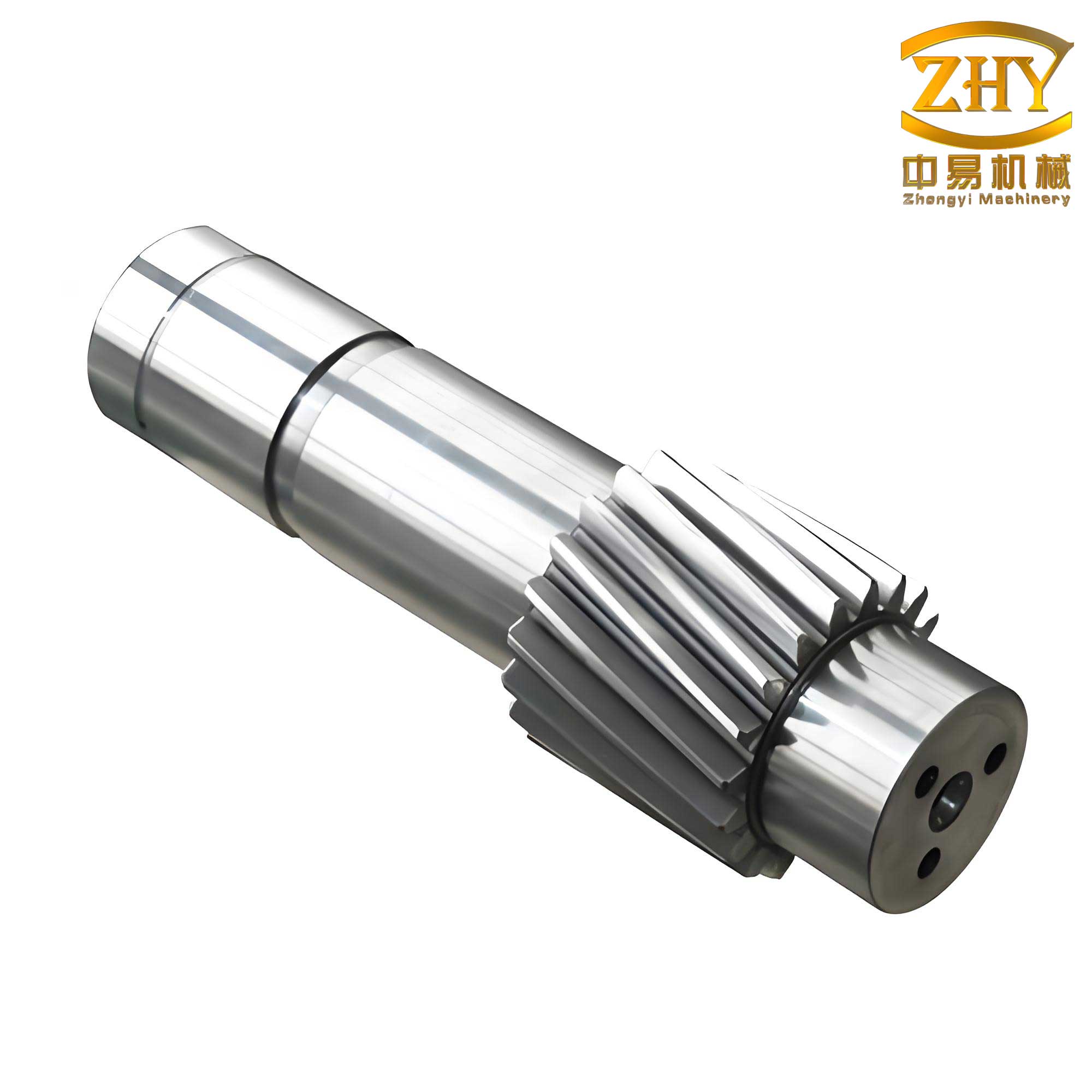
In my role as an engineer specializing in mechanical component reliability, I recently encountered a critical failure involving a bevel gear shaft from a high-end speed reducer unit. The gear shaft, after a period of operation at a client’s site, exhibited seizure with its bearing and subsequently developed a severe longitudinal crack. This incident prompted a detailed forensic investigation to determine the root cause and prevent future occurrences. The gear shaft in question was a forged component made from 18CrNiMo7-6 steel, having undergone a series of heat treatments including carburizing, quenching, and tempering. The initial observation was alarming: the crack, originating from the bearing fitting area, propagated axially over 240 mm and continued to extend even during storage, suggesting a delayed failure mechanism. This report documents my first-person analytical journey, employing various techniques to unravel the mystery behind this gear shaft failure.
The core of my investigation revolved around understanding the failure mode through a multi-faceted approach. The primary suspect was the gear shaft’s material integrity and the stresses it endured. I began with a macro-examination of the fractured gear shaft. The crack path was predominantly axial, with the fracture surface appearing relatively flat and devoid of significant plastic deformation, indicative of a brittle fracture mechanism. The origin was pinpointed to the region where the gear shaft interfaced with the bearing inner race, a classic stress concentration zone.
Moving to a microscopic level, I conducted scanning electron microscopy (SEM) on the fracture surface after ultrasonic cleaning. The findings were revealing. The crack initiation site was at the interface between the carburized case and the core material of the gear shaft. At higher magnifications, the fracture morphology in both the initiation and propagation zones exhibited a distinct intergranular character. This was in stark contrast to the ductile dimple morphology observed on a freshly broken sample of the gear shaft’s base material, which I created for comparison. Energy dispersive X-ray spectroscopy (EDS) was performed on various locations of the fracture surface to check for corrosive elements. The results, summarized in Table 1, showed primarily base metal constituents (Fe, Cr, Ni, C, Mn, Mo) with some oxygen, likely from post-fracture exposure, but no aggressive contaminants like chlorides or sulfides were detected. This ruled out stress corrosion cracking as a primary cause.
| Location | Fe | Cr | Ni | C | Si | O | Mn | Mo | Other |
|---|---|---|---|---|---|---|---|---|---|
| Crack Origin | 82.96 | 1.75 | 1.15 | 8.10 | – | – | 0.75 | – | 5.28 |
| Crack Origin | 83.47 | 1.79 | 1.07 | 6.66 | – | – | 0.65 | – | 6.35 |
| Propagation Zone | 78.14 | 1.59 | 0.92 | 8.97 | 0.33 | 4.96 | 0.52 | – | 4.07 |
| Propagation Zone | 84.95 | 1.68 | 1.13 | 4.43 | 0.29 | 2.14 | 0.84 | – | 4.54 |
| Near Spline End | 67.95 | 2.30 | 1.45 | 15.51 | 0.43 | 6.42 | 0.56 | 0.84 | 4.25 |
| Near Spline End | 75.21 | 1.98 | 1.31 | 11.23 | 0.43 | 4.06 | 0.78 | 0.81 | 4.20 |
To assess the material’s inherent soundness, I examined the macrostructure of a transverse section from the cracked gear shaft. The low-magnification structure showed no apparent defects like voids, inclusions, or significant segregation, confirming the forging quality was acceptable. Microstructural analysis was then performed. The carburized layer at the edge of the gear shaft showed a normal microstructure without deleterious network carbides. The core microstructure consisted of tempered martensite, which is the expected and desired structure for this grade of steel after its heat treatment cycle. The microstructure adjacent to the crack path also showed no anomalies, indicating the crack propagated through sound material and was not guided by microstructural defects.
Hardness is a critical property as it relates directly to strength and susceptibility to certain failure modes. I measured the microhardness of the gear shaft’s core material using a Vickers indenter. The results, converted to Rockwell C scale for broader engineering context, are shown in Table 2. The average hardness of approximately 349 HV0.5 (or 36.5-37.0 HRC) corresponds to a tensile strength ($R_m$) of about 1100 MPa, as per standard conversion charts. This places the gear shaft in the medium-to-high strength category. The formula for estimating tensile strength from Vickers hardness (for steels) can be approximated as:
$$ R_m \text{ (in MPa)} \approx 3.2 \times HV $$
For our measured average, this gives $R_m \approx 3.2 \times 348.76 \approx 1116 \text{ MPa}$, confirming its high-strength status.
| Hardness Measurements (HV0.5) | Average Hardness (HV0.5) | Converted Hardness (HRC) | Estimated Tensile Strength, $R_m$ (MPa) |
|---|---|---|---|
| 329.36, 355.88, 336.28, 354.60, 367.66 | 348.76 | 36.5 – 37.0 | ~1116 |
A pivotal part of my analysis was determining the hydrogen content within the gear shaft material. Hydrogen, even in minute quantities, can be devastating to high-strength steels. I extracted a sample from the core region of the failed gear shaft and performed hydrogen analysis. The results were telling: the hydrogen content exceeded $3 \times 10^{-6}$ (3 ppm by weight), with measurements reaching up to $4 \times 10^{-6}$, as shown in Table 3. The specified technical requirement for this component was a maximum hydrogen content of $2 \times 10^{-6}$. This elevated hydrogen level was a significant red flag.
| Measured Hydrogen Content (×10$^{-6}$) | Average Content (×10$^{-6}$) | Specification Limit (×10$^{-6}$) |
|---|---|---|
| 1, 3, 4, 4, 4 | > 3 | ≤ 2 |
Synthesizing all the evidence, I arrived at a definitive conclusion regarding the failure nature. The combination of intergranular fracture morphology, delayed crack propagation post-service, initiation at a stress concentration point (the bearing seat on the gear shaft), and most importantly, the elevated hydrogen content in a high-strength material, collectively points to Hydrogen-Induced Delayed Brittle Fracture, commonly known as hydrogen embrittlement. The artificial fracture of the base gear shaft material showed ductile behavior, proving the inherent toughness of the material was compromised by the presence of hydrogen.
The mechanism of hydrogen embrittlement in a high-strength gear shaft like this one is complex but well-studied. Atomic hydrogen, present in the steel lattice, preferentially segregates to regions of high triaxial stress, such as grain boundaries and the plastic zone ahead of a crack tip or notch. This accumulation reduces the cohesive strength of the metal lattice, facilitating crack initiation and propagation under sustained or cyclic stress levels below the material’s yield strength. The critical factors can be framed by the following relationship for the threshold stress intensity for hydrogen-assisted cracking ($K_{IH}$):
$$ K_{IH} = f(C_H, \sigma_y, \text{microstructure}) $$
where $C_H$ is the hydrogen concentration, and $\sigma_y$ is the yield strength. For this gear shaft, both $C_H$ and $\sigma_y$ (related to hardness) were high, driving $K_{IH}$ down and making the component very susceptible.
The source of hydrogen in this gear shaft is a crucial question. Hydrogen can be introduced during several stages: steelmaking, heat treatment (especially in atmospheres containing moisture), electroplating, or pickling. This particular gear shaft did not undergo any plating or acid cleaning processes. The most probable source was the carburizing heat treatment cycle. While modern carburizing is often done in controlled atmospheres, trace moisture can dissociate at high temperatures, introducing atomic hydrogen into the steel surface, which then diffuses inward. The subsequent post-quench tempering at 150°C for 4 hours was evidently insufficient to fully dehydrogenate this high-strength gear shaft. The diffusion of hydrogen is governed by Fick’s laws. The time ($t$) required to reduce the hydrogen concentration at the center of a component can be estimated. For a cylindrical geometry approximating a gear shaft, the solution to Fick’s second law for desorption gives a characteristic time constant proportional to the square of the radius ($r$):
$$ t \propto \frac{r^2}{D} $$
where $D$ is the diffusion coefficient of hydrogen in steel, which is strongly temperature-dependent:
$$ D = D_0 \exp\left(-\frac{Q}{RT}\right) $$
Here, $D_0$ is a pre-exponential factor, $Q$ is the activation energy for diffusion, $R$ is the gas constant, and $T$ is the absolute temperature. At a low tempering temperature of 150°C (423 K), the diffusion coefficient $D$ is very small, meaning the required time for significant hydrogen removal is impractically long for a standard industrial cycle. For a gear shaft with a significant diameter, the hydrogen trapped in the core may not have enough time to escape.
Furthermore, the role of residual stress cannot be overstated. The quenching process after carburizing generates substantial compressive stresses in the case but can also create tensile residual stresses in the subsurface and core regions of the gear shaft. These residual stresses, combined with the applied stresses from the interference fit with the bearing and the operational loads, created a potent driving force for crack initiation. The observation that the crack continued to grow during storage is a classic hallmark of a failure driven by internal residual stresses in a hydrogen-embrittled material. The total stress ($\sigma_{total}$) at the critical location on the gear shaft can be considered as a superposition:
$$ \sigma_{total} = \sigma_{applied} + \sigma_{residual} + \sigma_{stress\;concentration} $$
where $\sigma_{applied}$ comes from service loads and fit, $\sigma_{residual}$ is from heat treatment, and $\sigma_{stress\;concentration}$ is the geometric factor at the bearing seat. Even with $\sigma_{applied}$ removed after failure, $\sigma_{residual}$ remained sufficiently high to propagate the crack in the presence of hydrogen.
To quantify the risk, the concept of a critical hydrogen concentration ($C_{crit}$) for a given stress level and material strength is useful. An empirical relationship often cited is:
$$ C_{crit} \propto \exp\left(-\frac{\sigma_h}{S}\right) $$
where $\sigma_h$ is the hydrostatic stress and $S$ is a material constant. For high-strength gear shafts, $C_{crit}$ can be extremely low, sometimes below $1 \times 10^{-6}$. The measured hydrogen content of $>3 \times 10^{-6}$ in this gear shaft far exceeded such a threshold, especially at the stress-concentrated bearing seat.
Based on my analysis, the failure sequence for this gear shaft can be reconstructed. During service, the interference fit and rotation created stresses at the bearing contact area on the gear shaft. The gear shaft, already charged with hydrogen from processing and under high residual stresses, experienced hydrogen migration to these high-stress zones. This weakening of grain boundaries eventually led to the initiation of an intergranular micro-crack. The subsequent seizure event between the gear shaft and the bearing, likely due to lubrication failure or misalignment, imposed an abrupt, high stress surge, accelerating crack propagation. Finally, even after removal from service, the persistent tensile residual stresses within the gear shaft provided the energy for continued slow, hydrogen-assisted crack growth, leading to the observed long axial crack.
The investigation clearly points to necessary corrective and preventive actions. The root cause was hydrogen embrittlement of a high-strength gear shaft, catalyzed by insufficient dehydrogenation heat treatment and significant residual stresses. Therefore, my primary recommendations focus on modifying the heat treatment protocol for future gear shafts of this type. The tempering process must be optimized to effectively reduce both hydrogen content and residual stress. Increasing the temperature and duration is key. The diffusion coefficient $D$ increases exponentially with temperature. Raising the tempering temperature from 150°C to, for example, 180°C (453 K) can increase $D$ by a factor of approximately:
$$ \frac{D_{180}}{D_{150}} = \exp\left[-\frac{Q}{R}\left(\frac{1}{453} – \frac{1}{423}\right)\right] $$
For hydrogen diffusion in ferritic steel, with $Q \approx 35 \text{ kJ/mol}$, this ratio is roughly 2.5. This means hydrogen diffuses out 2.5 times faster. More importantly, the higher temperature also promotes more effective relief of quenching-induced residual stresses through enhanced dislocation mobility and recovery processes.
Consequently, I propose the following revised heat treatment step for the gear shaft after quenching: implement a tempering cycle at $180^\circ \text{C}$ for a minimum of 8 hours, replacing the previous $150^\circ \text{C}$ for 4 hours. This extended bake-out treatment will provide a much greater driving force and time for hydrogen egress from the core of the gear shaft. Furthermore, it will significantly lower the residual stress levels, reducing the static stress component that drives hydrogen-assisted cracking. To validate the effectiveness, a control plan should include regular hydrogen content checks on finished gear shafts using hot extraction or similar methods, ensuring levels are consistently below the $2 \times 10^{-6}$ specification.
In conclusion, this failure analysis of the bevel gear shaft underscores the critical interplay between material strength, hydrogen content, and stress state. For high-performance components like this gear shaft, even minor deviations in post-heat treatment processing can lead to catastrophic delayed failures. The gear shaft’s journey from a forged blank to a precision component must include a robust dehydrogenation strategy. By implementing a higher-temperature, longer-duration tempering cycle, the susceptibility of the gear shaft to hydrogen embrittlement can be drastically reduced, ensuring the reliability and longevity of the speed reducer assembly. This case serves as a potent reminder that in the realm of high-strength steel components, invisible threats like atomic hydrogen demand vigilant control through carefully designed and validated thermal processes.