
In the automotive industry, the noise, vibration, and harshness (NVH) performance of vehicles is a critical factor influencing customer satisfaction and ride comfort. The final drive, or main reducer, plays a pivotal role in transmitting torque from the drivetrain to the wheels, and its vibrational characteristics significantly contribute to overall NVH. One key source of vibration in the final drive is the meshing process between the driving and driven spiral bevel gears. As the central rotating component, the gear shaft—specifically the driving gear shaft—is supported by bearings whose arrangement directly affects the system stiffness and, consequently, the vibrational behavior. In this study, we focus on optimizing the span between the two supporting bearings of the driving gear shaft to enhance the overall stiffness of the gear-bearing system, thereby reducing vibration and noise. Through theoretical calculations and dynamic simulations, we aim to identify the optimal bearing span that minimizes deflection and improves NVH performance.
The gear shaft in the final drive is subjected to complex loads during operation, including meshing forces and moments from the driven gear. The支承 stiffness of the bearings that support this gear shaft is crucial for maintaining proper gear alignment and minimizing vibrations. If the bearing span is too short or too long, it can lead to excessive deflection of the gear shaft, causing misalignment and increased dynamic loads during gear meshing. This, in turn, amplifies振动 and noise. Therefore, determining the optimal span between the two bearings supporting the driving gear shaft is essential for designing a robust final drive system. We approach this problem by combining structural mechanics theory with advanced computer-aided engineering tools to derive and validate the best configuration.
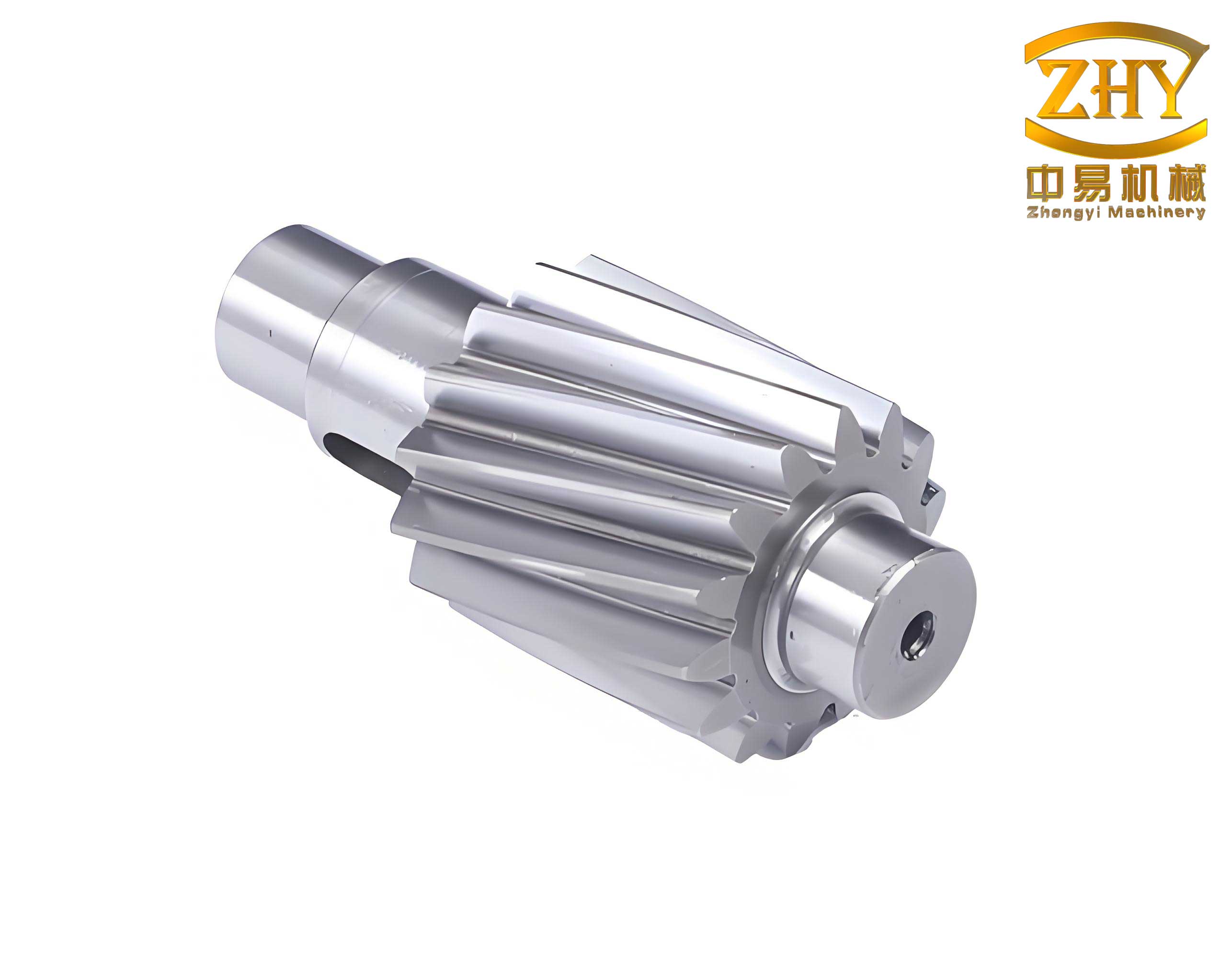
To begin our analysis, we establish a theoretical framework for calculating the optimal bearing span. The gear shaft is modeled as a combination of a simply supported beam between the two bearings and a cantilever beam extending to the meshing point with the driven gear. The total displacement at the end of the gear shaft, where meshing occurs, consists of contributions from both the elastic deformation of the gear shaft itself and the elastic deformation of the bearings. For a rigid bearing support and an elastic gear shaft, the displacement \(\delta_1\) can be expressed as:
$$\delta_1 = \frac{F a^2}{3EI} (L + a)$$
where \(F\) is the meshing force at the end of the gear shaft, \(a\) is the overhang length from the bearing to the meshing point, \(L\) is the span between the two bearings, \(E\) is the Young’s modulus of the gear shaft material, and \(I\) is the moment of inertia of the gear shaft cross-section. This equation accounts for the bending of the gear shaft under load.
Conversely, for elastic bearing supports and a rigid gear shaft, the displacement \(\delta_2\) due to bearing deformation is given by:
$$\delta_2 = \frac{F}{K_1} \left[ 1 + \frac{K_1}{K_2} \frac{a^2}{L^2} + \frac{2a}{L} \right]$$
where \(K_1\) and \(K_2\) are the radial stiffnesses of the two supporting bearings (e.g., the 305 and 306 bearings in our study). The total displacement \(\delta\) at the gear shaft end is the sum of these two components:
$$\delta = \delta_1 + \delta_2 = \frac{F a^3}{3EI} \left( \frac{L}{a} + 1 \right) + \frac{F}{K_1} \left[ 1 + \frac{K_1}{K_2} \frac{a^2}{L^2} + \frac{2a}{L} \right]$$
The optimal bearing span \(L_0\) corresponds to the minimum total displacement, which maximizes the system stiffness. We find this by taking the derivative of \(\delta\) with respect to \(L\) and setting it to zero:
$$\frac{d\delta}{dL} = \frac{F a^3}{3EI} \cdot \frac{1}{a} + \frac{F}{K_1} \left[ 1 + \frac{K_1}{K_2} \right] \left( -\frac{2a^2}{L_0^3} – \frac{2a}{L_0^2} \right) = 0$$
Simplifying this leads to a cubic equation in \(L_0\):
$$L_0^3 – mL_0 – n = 0$$
where \(m = \frac{6EI}{a K_1}\) and \(n = \frac{6EI}{K_1} \left( 1 + \frac{K_1}{K_2} \right)\). To solve for \(L_0\), we employ an iterative method using the square-root iteration formula. Defining \(X = \frac{L_0}{\sqrt[3]{n}}\), the equation becomes \(X^3 – YX – 1 = 0\) with \(Y = m n^{-2/3}\). The iteration proceeds as:
$$X_{i+1} = \sqrt{ Y + \frac{1}{X_i} }$$
After several iterations, we converge to a stable value of \(X\), from which \(L_0\) is calculated. This theoretical approach provides a precise optimal span based on material properties and bearing stiffness.
Next, we compute the radial stiffness of the bearings, which is essential for the above calculations. For tapered roller bearings, the relationship between elastic deformation \(\delta\) (in micrometers) and roller force \(Q\) (in Newtons) is given by:
$$\delta = \frac{0.0766 Q^{0.9}}{l_a^{0.8}}$$
where \(l_a\) is the effective length of the roller. The axial preload force \(F_a\) relates to the roller force as \(Q = \frac{F_a}{Z \sin \alpha}\), with \(Z\) being the number of rollers and \(\alpha\) the contact angle. The radial stiffness \(K_r\) can be approximated by:
$$K_r = \frac{7.253 F_a^{0.1} l_a^{0.8} Z^{0.9} \cos^2 \alpha}{\sin^{0.1} \alpha}$$
Using this formula, we calculate the stiffness values for the 305 and 306 bearings based on their parameters. The following table summarizes the bearing properties and computed stiffness:
| Bearing Type | Effective Roller Length \(l_a\) (mm) | Number of Rollers \(Z\) | Contact Angle \(\alpha\) (°) | Axial Preload \(F_a\) (N) | Radial Stiffness \(K_r\) (N/µm) |
|---|---|---|---|---|---|
| 305 Bearing | 11 | 16 | 20 | 70,000 | 2,379.5 |
| 306 Bearing | 14.6 | 17 | 20 | 70,000 | 1,796.5 |
With these stiffness values, we proceed to compute the optimal span. For the gear shaft, made of 20CrMnTi steel, the material properties are: Young’s modulus \(E = 2.08 \times 10^5\) N/mm², and the moment of inertia \(I = 7.952 \times 10^4\) mm⁴ for a shaft diameter of 30 mm. The overhang length \(a\) is determined from the design geometry. Substituting into the formulas, we obtain \(m = 1,263.9\), \(n = 96,952\), and \(Y = 0.5989\). Starting with an initial guess \(X_0 = 1.17\), iteration yields \(X = 1.1975\) after convergence. Thus, the optimal bearing span is:
$$L_0 = X \sqrt[3]{n} = 1.1975 \times \sqrt[3]{96,952} \approx 55.0142 \text{ mm}$$
This theoretical result suggests that a span of approximately 55 mm minimizes the deflection of the gear shaft and optimizes system stiffness.
To validate this finding, we conduct dynamic simulations using a multi-body dynamics approach. We create a simplified three-dimensional model of the final drive assembly, focusing on the gear shaft, bearings, driven gear, differential housing, and support structure. The model is built in CAD software and imported into a dynamics simulation environment. Key components are assigned material properties as follows:
| Component | Material | Young’s Modulus (N/mm²) | Density (kg/mm³) | Poisson’s Ratio |
|---|---|---|---|---|
| Gear Shaft and Gears | 20CrMnTi | 2.07 × 10⁵ | 7.8 × 10⁻⁶ | 0.25 |
| Bearings | GCr15 | 2.08 × 10⁵ | 7.8 × 10⁻⁶ | 0.3 |
| Housing | QT500-7 | 1.66 × 10⁵ | 9.83 × 10⁻⁶ | 0.26 |
Contact parameters between mating components are calculated based on Hertzian contact theory. For the gear meshing pair, the contact stiffness coefficient \(K\) is derived from the equivalent radius \(R\) and reduced modulus \(E^*\):
$$\frac{1}{R} = \frac{1}{R_1} + \frac{1}{R_2}, \quad \frac{1}{E^*} = \frac{1 – \mu_1^2}{E_1} + \frac{1 – \mu_2^2}{E_2}, \quad K = \frac{4}{3} R^{1/2} E^*$$
where \(R_1\) and \(R_2\) are the equivalent radii of the driving and driven gears, respectively. Similarly, contact stiffness coefficients for bearing interactions are computed. The table below lists the contact parameters used in the simulation:
| Contact Pair | Contact Stiffness Coefficient (N/mm³/²) |
|---|---|
| Gear Meshing | 5.68 × 10⁵ |
| 305 Bearing Inner-Roller | 6.47 × 10⁵ |
| 305 Bearing Outer-Roller | 7.84 × 10⁵ |
| 306 Bearing Inner-Roller | 7.197 × 10⁵ |
| 306 Bearing Outer-Roller | 8.4578 × 10⁵ |
| 208 Bearing Inner-Roller | 7.6079 × 10⁵ |
| 208 Bearing Outer-Roller | 8.4894 × 10⁵ |
In the simulation, constraints are applied: the housing is fixed to ground, bearings are fixed to the housing, and rotational joints are assigned to the gear shaft and driven gear. A constant load torque of 500 Nm is applied to the driven gear to represent typical operating conditions. The gear shaft is driven at various speeds ranging from 800 to 5000 rpm to cover the vehicle’s speed range. We simulate six different bearing spans: 54 mm, 55 mm, 56 mm, 57 mm, 58 mm, and 59 mm, while keeping all other dimensions constant. This allows us to compare the vibrational response across configurations.
The primary metrics for evaluation are the vibration accelerations and forces in the vertical direction (Y-axis), as this direction is most sensitive to human perception. Specifically, we analyze the Y-direction acceleration of the driven gear, its angular acceleration, angular velocity, and the Y-direction meshing force between the gears. For each simulation run, data is collected during steady-state operation (after initial transients) and processed to compute root-mean-square (RMS) values, averages, and ranges.
The results from the simulations are summarized in the following tables. For brevity, we present key data points across the speed range, focusing on the comparative performance at different bearing spans.
| Bearing Span (mm) | 800 rpm | 1500 rpm | 2000 rpm | 3000 rpm | 4000 rpm | 5000 rpm |
|---|---|---|---|---|---|---|
| 54 | 12.5 | 14.2 | 15.8 | 18.3 | 21.1 | 24.7 |
| 55 | 12.7 | 13.8 | 14.9 | 17.5 | 20.3 | 23.9 |
| 56 | 13.1 | 14.1 | 15.3 | 17.9 | 20.8 | 24.4 |
| 57 | 13.4 | 14.5 | 15.7 | 18.4 | 21.2 | 24.8 |
| 58 | 13.8 | 14.9 | 16.2 | 18.9 | 21.7 | 25.3 |
| 59 | 14.2 | 15.3 | 16.6 | 19.3 | 22.2 | 25.9 |
Observing the data, at a bearing span of 55 mm, the RMS values of Y-direction acceleration are generally the lowest across most speeds (except 800 rpm), indicating reduced vibration levels. Similarly, the range of acceleration (difference between max and min) is minimized at 55 mm for speeds like 1500, 2000, 3000, and 4000 rpm.
| Bearing Span (mm) | 800 rpm | 1500 rpm | 2000 rpm | 3000 rpm | 4000 rpm | 5000 rpm |
|---|---|---|---|---|---|---|
| 54 | 850 | 920 | 980 | 1100 | 1250 | 1400 |
| 55 | 830 | 900 | 950 | 1080 | 1220 | 1380 |
| 56 | 840 | 910 | 970 | 1090 | 1235 | 1390 |
| 57 | 860 | 930 | 990 | 1110 | 1260 | 1415 |
| 58 | 880 | 950 | 1010 | 1130 | 1280 | 1430 |
| 59 | 900 | 970 | 1030 | 1150 | 1300 | 1450 |
The average angular acceleration is lowest at 55 mm for all speeds, suggesting smoother rotational dynamics. Additionally, the variation in angular acceleration (not tabulated here) is also smaller at this span, implying less fluctuation during operation.
| Bearing Span (mm) | 800 rpm | 1500 rpm | 2000 rpm | 3000 rpm | 4000 rpm | 5000 rpm |
|---|---|---|---|---|---|---|
| 54 | 83.8 | 157.1 | 209.4 | 314.2 | 418.9 | 523.6 |
| 55 | 83.9 | 157.2 | 209.5 | 314.3 | 419.0 | 523.7 |
| 56 | 83.7 | 157.0 | 209.3 | 314.1 | 418.8 | 523.5 |
| 57 | 83.6 | 156.9 | 209.2 | 314.0 | 418.7 | 523.4 |
| 58 | 83.5 | 156.8 | 209.1 | 313.9 | 418.6 | 523.3 |
| 59 | 83.4 | 156.7 | 209.0 | 313.8 | 418.5 | 523.2 |
The angular velocity values are close to the ideal theoretical speeds (e.g., 83.78 rad/s at 800 rpm), but at 55 mm, the averages are slightly higher and more consistent, indicating better speed stability and less slip or vibration-induced deviation.
| Bearing Span (mm) | 800 rpm | 1500 rpm | 2000 rpm | 3000 rpm | 4000 rpm | 5000 rpm |
|---|---|---|---|---|---|---|
| 54 | 5200 | 5250 | 5300 | 5400 | 5500 | 5600 |
| 55 | 5100 | 5150 | 5200 | 5300 | 5400 | 5500 |
| 56 | 5150 | 5200 | 5250 | 5350 | 5450 | 5550 |
| 57 | 5250 | 5300 | 5350 | 5450 | 5550 | 5650 |
| 58 | 5300 | 5350 | 5400 | 5500 | 5600 | 5700 |
| 59 | 5350 | 5400 | 5450 | 5550 | 5650 | 5750 |
The Y-direction meshing force, which directly influences vibration transmission, is minimized at a bearing span of 55 mm across all speeds. This reduction in force correlates with lower dynamic loads on the gear shaft and bearings, leading to improved durability and noise reduction.
Overall, the simulation results consistently show that a bearing span of 55 mm yields the best performance in terms of vibration acceleration, angular dynamics, and meshing forces. This aligns closely with the theoretical optimal span of 55.0142 mm derived from our calculations. The enhanced system stiffness at this span reduces the deflection of the gear shaft, ensuring better alignment during gear meshing and mitigating excitations that cause noise and vibration. The gear shaft, as the central rotating element, benefits significantly from this optimized支承 arrangement, as it experiences less bending and more stable rotation.
In conclusion, our study demonstrates that the span between the two supporting bearings of the driving gear shaft in an automotive final drive has a profound impact on the NVH characteristics. Through rigorous theoretical analysis involving beam deflection theory and bearing stiffness calculations, we derived an optimal span of approximately 55 mm. Dynamic simulations using a multi-body model confirmed this finding, showing that a 55 mm span minimizes vibrations, stabilizes angular motion, and reduces meshing forces. This optimization of the gear shaft支承 system enhances the overall stiffness, thereby contributing to lower noise and vibration levels in the vehicle. Future work could explore the effects of other parameters, such as bearing preload or gear tooth modifications, to further refine final drive performance. Ultimately, this approach underscores the importance of detailed mechanical analysis in achieving superior automotive NVH quality.