
In the field of metal forming, the extrusion forging of gear shaft components presents significant challenges due to the complex geometry of the tooth structures. As a researcher focused on optimizing forging processes, I have observed that during the final stages of forging, substantial forging pressure is required to force the billet into the tooth tips of the gear shaft, which can adversely affect mold life and increase equipment demands. Therefore, improving mold design to enhance forging quality is critical. In this study, I investigate the use of splitter structures in the mold to improve material flow in hard-to-fill regions, thereby reducing required forging pressure and enhancing overall gear shaft quality. The gear shaft, a key component in many mechanical systems, requires high precision and strength, making this analysis vital for industrial applications.
The comprehensive quality evaluation system for forgings must consider not only the quality of the gear shaft itself but also factors such as mold usage次数 (where higher forging pressures cause greater mold damage) and the maximum forging force needed (which dictates equipment tonnage). Minimizing forging force while ensuring adequate fill performance is essential, and splitter structures near difficult-to-fill areas offer an effective solution. This article focuses on the extrusion forging of a specific gear shaft model, analyzing how splitter structure dimensions impact forging quality through simulation and parameter studies.
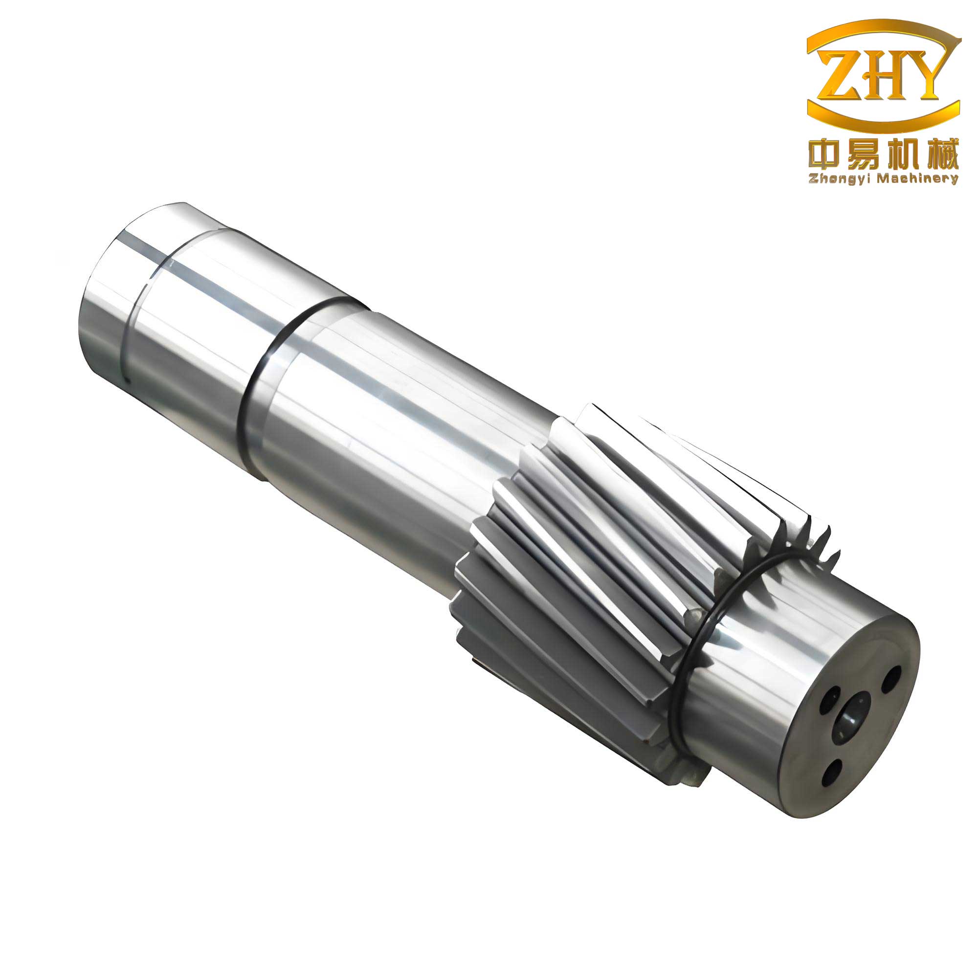
To begin, I established the parameters for the extrusion forging simulation. The gear shaft structure consists of a tooth section and a shaft section, with the tooth section positioned centrally on the shaft. The left shaft has a length of 171 mm and a diameter of 52 mm, while the right shaft is 68 mm long with a diameter of 78 mm. The tooth section width is 46 mm, with a gear addendum circle of 142 mm, pitch circle of 126 mm, and dedendum circle of 112 mm, featuring a module of 7 mm and 18 teeth. For material selection, I chose 40Cr steel due to its high strength, hardness, excellent machinability, wear resistance, and high-temperature fluidity, which are crucial for gear shaft performance under cyclic stresses. The properties of 40Cr steel are summarized in Table 1.
| Property | Value | Unit |
|---|---|---|
| Elastic Modulus | 210 | GPa |
| Tensile Strength | 990 | MPa |
| Density | 7.95 | g/cm³ |
| Poisson’s Ratio | 0.298 | – |
The extrusion forging process involves placing a preheated billet into a preheated mold and applying force via punches to form the gear shaft. The mold structure comprises a left punch, left mold, tooth mold, right mold, and right punch, with splitter grooves on the faces near the tooth mold to guide material flow. Key process parameters include a billet preheat temperature of 900°C, mold preheat temperature of 280°C, external gas temperature of 25°C, convective heat transfer coefficient of 0.02 W/(m²·°C), thermal conductivity coefficient of 10.85 W/(m²·°C), and a punch loading rate of 6.5 mm/s. These settings ensure realistic simulation conditions for analyzing gear shaft forging.
The splitter groove structure on the mold end face includes a guide section and a fill section. The guide section consists of an arc and a斜面, with an arc radius of 10 mm and a斜面 transition angle α. The fill section has a square cross-section, where dimensions L1 (groove width), L2 (guide width), and H (groove depth) are interdependent. In my analysis, I focused on H, L1, and α as key parameters affecting forging quality. To quantify material behavior, I used a flow stress model common in forging simulations, represented by the formula: $$\sigma = K \epsilon^n$$ where $\sigma$ is the flow stress, $\epsilon$ is the strain, and K and n are material constants for 40Cr steel. This helps in predicting material deformation during gear shaft forming.
First, I examined the effect of splitter groove depth H on forging quality by simulating different H values and recording the maximum mold load, which correlates with forging pressure. The results are shown in Table 2 and Figure 1. As H increased from 2 mm to 4 mm, the maximum load decreased rapidly initially, then slowly, before stabilizing. For instance, at H = 2 mm, the load was 1230 kN, dropping to 1072 kN at H = 2.7 mm, and leveling around 1035 kN for H ≥ 3.3 mm. This indicates that increasing groove depth enhances material flow in critical areas of the gear shaft, reducing required force, but beyond 3.3 mm, further gains are minimal. The relationship can be approximated by a piecewise function: $$F(H) = \begin{cases} 1230 – 226(H-2) & \text{for } 2 \leq H < 2.7 \\ 1072 – 72(H-2.7) & \text{for } 2.7 \leq H < 3.3 \\ 1035 & \text{for } H \geq 3.3 \end{cases}$$ where F is the maximum load in kN.
| Groove Depth H (mm) | Maximum Mold Load (kN) |
|---|---|
| 2.0 | 1230 |
| 2.2 | 1198 |
| 2.4 | 1166 |
| 2.6 | 1134 |
| 2.7 | 1072 |
| 2.8 | 1060 |
| 3.0 | 1048 |
| 3.2 | 1042 |
| 3.3 | 1036 |
| 3.4 | 1035 |
| 3.6 | 1035 |
| 3.8 | 1035 |
| 4.0 | 1035 |
Next, I analyzed the impact of splitter groove width L1 on the gear shaft forging process. Keeping other parameters constant (H = 3.3 mm, α = 40°), I varied L1 from 6 mm to 13 mm and observed the maximum mold load. The data in Table 3 shows a similar trend: as L1 increased, the load decreased quickly at first, then more gradually. For example, at L1 = 6 mm, the load was 1047 kN, falling to 1006 kN at L1 = 8.5 mm, and slowly approaching 1000 kN for larger widths. This suggests that wider grooves improve material流动性, but beyond 8.5 mm, the effect diminishes. The relationship can be modeled as: $$F(L1) = 1047 – 16.4(L1-6) \quad \text{for } 6 \leq L1 < 8.5$$ $$F(L1) = 1006 – 1.3(L1-8.5) \quad \text{for } L1 \geq 8.5$$ This optimization is crucial for designing efficient molds for gear shaft production.
| Groove Width L1 (mm) | Maximum Mold Load (kN) |
|---|---|
| 6.0 | 1047 |
| 6.5 | 1039 |
| 7.0 | 1031 |
| 7.5 | 1023 |
| 8.0 | 1015 |
| 8.5 | 1006 |
| 9.0 | 1005 |
| 9.5 | 1004 |
| 10.0 | 1003 |
| 10.5 | 1002 |
| 11.0 | 1001 |
| 11.5 | 1001 |
| 12.0 | 1000 |
| 12.5 | 1000 |
| 13.0 | 1000 |
Finally, I studied the influence of the斜面 transition angle α on gear shaft forging quality. With H = 3.3 mm and L1 = 8.5 mm, I varied α from 20° to 60°. The results in Table 4 indicate that as α increased, the maximum load decreased rapidly until around 42°, remained low until 52°, then increased sharply. For instance, at α = 20°, the load was 1150 kN, dropping to 1010 kN at α = 42°, staying near 1000 kN up to α = 52°, and rising to 1220 kN at α = 60°. This nonlinear behavior highlights the importance of angle optimization for material flow in gear shaft forging. The relationship can be expressed as: $$F(\alpha) = 1150 – 6.36(\alpha-20) \quad \text{for } 20 \leq \alpha < 42$$ $$F(\alpha) \approx 1000 \quad \text{for } 42 \leq \alpha < 52$$ $$F(\alpha) = 1015 + 25.6(\alpha-52) \quad \text{for } 52 \leq \alpha \leq 60$$ These formulas aid in selecting optimal splitter designs.
| Transition Angle α (degrees) | Maximum Mold Load (kN) |
|---|---|
| 20 | 1150 |
| 25 | 1118 |
| 30 | 1086 |
| 35 | 1054 |
| 40 | 1022 |
| 42 | 1010 |
| 45 | 1005 |
| 48 | 1002 |
| 50 | 1001 |
| 52 | 1000 |
| 54 | 1015 |
| 56 | 1066 |
| 58 | 1142 |
| 60 | 1220 |
Based on my analysis, the optimal splitter structure parameters for gear shaft extrusion forging are H = 3.3 mm, L1 = 8.5 mm, and α = 42°. To validate this, I simulated the forging process with these settings and examined the fill condition of the tooth section. The results showed complete filling without defects at various punch displacement stages (e.g., 60%, 90%, and 100%下压量), confirming that the splitter effectively enhances material flow for the gear shaft. This optimization not only reduces forging pressure but also extends mold life, contributing to a more economical and reliable production process for gear shaft components.
In conclusion, my study demonstrates that splitter structures significantly improve gear shaft extrusion forging quality by facilitating material flow in hard-to-fill regions. Increasing groove depth and width generally reduces required forging force, but with diminishing returns beyond certain thresholds. The transition angle has a critical optimal range; too small or too large angles can increase loads. The identified parameter combination ensures efficient forging for gear shaft applications. Future work could explore other mold geometries or materials to further enhance gear shaft performance. This research underscores the importance of detailed simulation in advancing forging technologies for complex components like gear shafts.
To generalize these findings, I derived a comprehensive model for predicting maximum forging force in gear shaft extrusion with splitters. Considering material properties and geometry, the force F can be approximated as: $$F = A \cdot \sigma_{avg} \cdot f(H, L1, \alpha)$$ where A is the contact area, $\sigma_{avg}$ is the average flow stress, and f is a function of splitter parameters. For 40Cr steel, $\sigma_{avg}$ can be estimated using the formula: $$\sigma_{avg} = \frac{K \epsilon^n}{n+1}$$ integrating over the strain range. This approach allows for tailoring splitter designs to specific gear shaft requirements, promoting better quality and efficiency in industrial forging processes.