
In my recent investigation, I encountered a batch of gear shafts that exhibited subtle fluorescent magnetic particle indications during non-destructive testing. These gear shafts, manufactured from 12Cr2Ni4A steel and subjected to carbonitriding, are critical components in aerospace applications. The surface hardness specifications required a minimum of 60 HRC, with a case depth of at least 0.2 mm at the tooth root, while the core hardness was specified between 32 to 42 HRC. Out of 113 gear shafts in the batch, only four units displayed these indications, all localized at the tooth root regions on the end faces. This prompted a comprehensive analysis to determine the root cause and nature of these defects, focusing on the integrity of the gear shafts.
The initial step involved a macroscopic examination of the affected gear shafts. Visually, the gear shafts appeared normal with no obvious deformities or surface irregularities. However, under fluorescent magnetic particle inspection, fine linear indications were observed at specific tooth roots on the end faces. These indications were consistent in location and morphology across all defective gear shafts, suggesting a common origin. The indications were radial and axial in orientation, originating from the corner where the tooth root meets the transverse end face. To provide a visual reference of a typical gear shaft, the following image is inserted:
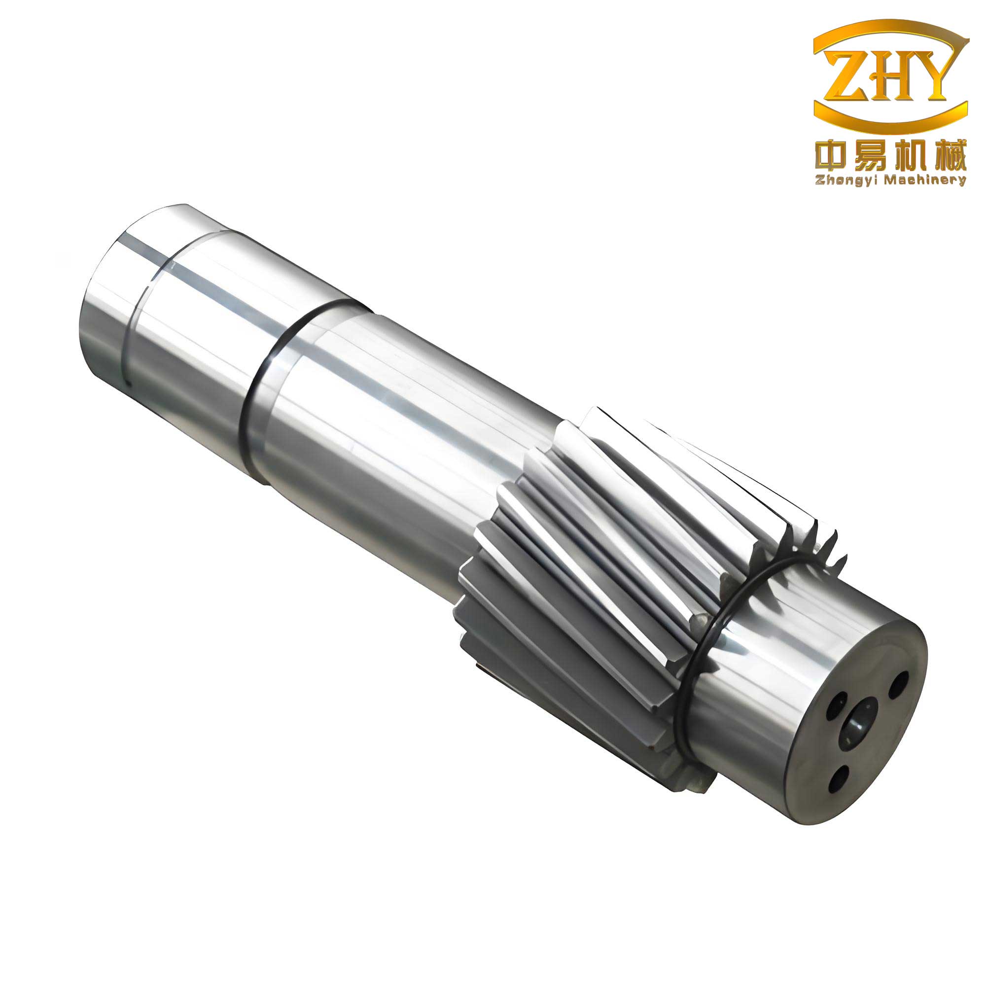
The precise positioning and dimensions of these cracks were critical for understanding their propagation. I documented four distinct cracks, labeled 1# through 4#, all residing on one half of the gear shaft’s circumference. Their dimensions, measured radially and axially, are summarized in the table below to illustrate their similarities and slight variations.
| Crack ID | Radial Length (mm) | Axial Length (mm) |
|---|---|---|
| 1# | 0.358 | 1.295 |
| 2# | 0.354 | 1.30 |
| 3# | 0.334 | 1.208 |
| 4# | 0.302 | ~1.20 |
To delve deeper, I performed fractographic analysis on artificially opened cracks, specifically 2# and 3#. The fracture surfaces were predominantly flat with negligible plastic deformation, indicative of brittle failure. The crack initiation sites were identified as small linear origins at the aforementioned corner, where the surface finish was notably rough and lacked proper fillet radius. The propagation zones exhibited primarily intergranular features, with isolated areas showing micro-void coalescence (dimples). The final fast fracture region, created during forced opening, displayed a dimpled morphology. This contrast highlights the brittle nature of the initial crack growth. The fracture mode can be conceptually represented by the dominance of intergranular decohesion, which often relates to environmental embrittlement or high tensile stress in susceptible microstructures. The stress intensity factor \( K \) at the crack tip, driving intergranular propagation, can be approximated for such surface flaws. For a surface crack of length \( a \) and depth \( b \), subjected to tensile stress \( \sigma \), the mode I stress intensity factor is often given by:
$$ K_I = Y \sigma \sqrt{\pi a} $$
where \( Y \) is a geometric factor dependent on crack shape and component geometry. In these gear shafts, the crack’s semi-elliptical shape at the stress-concentrating corner likely resulted in a \( Y \) value promoting rapid initiation and propagation under applied stresses.
Subsequent metallographic examination of cross-sections through the gear shafts revealed no abnormalities in the case or core microstructure. The carbonitrided layer exhibited carbides rated at level 1, with retained austenite and martensite at levels 1-2 according to relevant standards. The core microstructure consisted of tempered martensite and a minimal amount of ferrite, also within acceptable limits. However, the cracks themselves appeared tight, tapering inward, and were flanked by a slight increase in retained austenite content. This microstructural alteration near the cracks hinted at localized compositional changes. The integrity of the base material in these gear shafts was confirmed, ruling out inherent metallurgical defects as the cause.
Hardness testing provided further insights. Micro-hardness traverses and Rockwell hardness measurements were conducted on cross-sectional samples. The core hardness averaged approximately 41 HRC, meeting specifications. The surface hardness near the tooth root, measured at 0.1 mm depth, was around 690 HV. Converting Vickers hardness to Rockwell C scale is essential for specification compliance. The empirical relationship, based on standards like GB/T1172, can be complex, but a simplified approximation for high-hardness steels is often used. The conversion from HV to HRC is not linear, but for values around 690 HV, it corresponds to nearly 60 HRC. A more precise representation can involve a polynomial fit. For instance, a segment of the conversion can be modeled as:
$$ HRC \approx \alpha_0 + \alpha_1 (HV) + \alpha_2 (HV)^2 + \epsilon $$
where \( \alpha_i \) are coefficients derived from standard conversion tables. For our measured value of 690 HV, the equivalent is approximately 59.6 HRC, slightly below the 60 HRC minimum but unlikely to be the sole culprit. More strikingly, the micro-hardness in the immediate vicinity of the cracks was significantly higher than in non-cracked areas at the same depth, as detailed in the table below. This hardness elevation, coupled with increased retained austenite, pointed to carbon and nitrogen enrichment along the crack flanks.
| Measurement Area | Distance from Surface (mm) | Hardness (HV0.5) – Crack Zone | Hardness (HV0.5) – Sound Tooth 1 | Hardness (HV0.5) – Sound Tooth 2 |
|---|---|---|---|---|
| Tooth Root Hardness Gradient | 0.1 | 693.59 | 681.30 | 676.95 |
| 0.2 | 684.44 | 642.61 | 639.02 | |
| 0.3 | 680.23 | 574.71 | 580.21 | |
| 0.4 | 680.34 | 540.24 | 542.03 | |
| 0.5 | 673.65 | 504.46 | 514.12 | |
| 0.6 | 648.21 | 477.95 | 486.08 | |
| 0.7 | 627.10 | 458.97 | 461.21 | |
| 0.8 | 630.06 | 448.14 | 449.53 | |
| 0.9 | 604.20 | 435.88 | 438.49 | |
| 1.0 | 567.08 | 432.55 | 434.92 | |
| 1.1 | 528.67 | 434.22 | 434.03 |
The case depth, measured as the distance to 550 HV, was approximately 0.37 mm for non-cracked teeth, satisfying the requirement. The table below summarizes the surface and core hardness readings for clarity.
| Hardness Measurement Location | Value 1 | Value 2 | Value 3 | Average | Notes |
|---|---|---|---|---|---|
| Tooth Root Near Surface (HV0.5 at 0.1 mm) | 683.59 | 693.78 | 697.17 | 690.38 HV | ~59.6 HRC |
| Core Hardness (HRC) | 38.66 | 41.52 | 41.60 | 41 HRC | Within spec |
Synthesizing all evidence, I conducted a thorough analysis to determine the cause of these indications in the gear shafts. The intergranular brittle fracture morphology, combined with the specific location at stress-concentrating corners and the enrichment of carbon/nitrogen along crack flanks, pointed towards a stress-induced cracking event occurring after carbonitriding but before final hardening. The manufacturing process for these gear shafts included carbonitriding, high-temperature tempering, machining, quenching, sub-zero treatment, tempering, shot blasting, and finish machining. Crucially, the process flow did not officially include a straightening operation. However, quality control after high-temperature tempering required that the radial run-out of all external cylinders be within 0.1 mm. In practice, I learned that a few gear shafts exhibited excessive distortion post-carbonitriding and tempering, exceeding this tolerance. These out-of-spec gear shafts were subsequently subjected to manual straightening to correct run-out.
Straightening, particularly three-point bending, induces significant tensile stresses on the convex side of the bend. For a gear shaft under bending moment \( M \), the tensile stress \( \sigma_t \) at the outer fiber is given by:
$$ \sigma_t = \frac{M y}{I} $$
where \( y \) is the distance from the neutral axis to the outer surface, and \( I \) is the area moment of inertia. In a three-point bend setup, the maximum moment occurs at the midpoint. If the gear shaft is straightened with the tooth root region positioned on the tensile side, and considering the reduced ductility of the carbonitrided case (which is hard and brittle), the combination of high localized stress and a poor surface condition (sharp corner, rough machining marks) can readily initiate microcracks. The stress concentration factor \( K_t \) for such a notch further amplifies the applied stress:
$$ \sigma_{max} = K_t \sigma_{nominal} $$
These microcracks, formed during straightening, would then be present prior to the final quenching operation. The quenching was performed in a protective atmosphere with a carbon potential of about 0.88% to prevent decarburization. During the approximately one-hour hold at temperature, these pre-existing cracks acted as pathways for minor carbon and nitrogen diffusion, leading to the observed enrichment in their vicinity, which increased hardness and retained austenite. This explains why the cracks are confined to the case depth and show chemical/metallurgical alterations. The reason the cracks appeared only on one half of the circumference in these gear shafts aligns with the bending orientation during straightening, where only the region under maximum tensile stress would crack.
Therefore, the magnetic particle indications in these few gear shafts were conclusively identified as straightening-induced cracks. The brittle, intergranular nature is characteristic of stress cracking in hardened or case-hardened surfaces. The problem was not endemic to the batch but isolated to individual gear shafts that underwent corrective straightening without proper controls. To prevent recurrence, I recommended and helped implement process refinements. All gear shafts are now inspected for run-out after tempering. Those with minor deviations are straightened but must subsequently undergo stress relief annealing and mandatory magnetic particle inspection before proceeding to quenching. This ensures any straightening-induced defects are detected and eliminated, safeguarding the quality of the gear shafts.
In conclusion, my investigation into these gear shafts revealed that the fluorescent magnetic particle indications were caused by fine cracks. The crack morphology was predominantly intergranular and brittle, originating from stress concentrations at the tooth root end corners. The root cause was traced to an unregulated straightening operation performed on a subset of gear shafts that distorted beyond tolerances after carbonitriding. Inadequate control during straightening generated tensile stresses sufficient to initiate microcracks in the brittle case layer. Subsequent thermal processing modified the crack flanks, but the fundamental integrity breach occurred during mechanical straightening. This case underscores the criticality of controlling secondary operations like straightening on high-strength components such as gear shafts, and the necessity of non-destructive testing validation after such processes to ensure the reliability of these critical power transmission elements. The lessons learned have been incorporated into the manufacturing protocol, enhancing the consistency and defect-free production of gear shafts for demanding applications.