
The design and manufacturing of screw gears, encompassing both the worm and the worm wheel, constitute a critical aspect of power transmission engineering. As a system, the screw gear assembly is renowned for providing high reduction ratios within a compact spatial envelope, coupled with smooth and quiet operation. These characteristics make it an indispensable component in a vast array of industrial machinery, automotive steering systems, and precision instruments where significant speed reduction is paramount. My focus in this discussion is to detail a robust, parametric methodology for designing these components using the CATIA software platform. Parametric modeling is not merely a convenience; it is a paradigm that links design intent directly to geometry, allowing for rapid iteration, customization, and the creation of reusable component libraries. This approach is particularly powerful for standard yet configurable elements like screw gears.
CATIA, developed by Dassault Systèmes, stands as a premier solution in the realm of CAD/CAM/CAE. Its genesis in the aerospace industry has fostered an environment of extreme precision and advanced surface modeling capabilities. The software’s comprehensive suite supports the entire product development lifecycle, from initial conceptual design and complex 3D modeling to simulation and manufacturing. Its dominance in sectors such as automotive and aerospace is a testament to its robustness and versatility. For mechanical component design, CATIA’s parametric and associative modeling features are unparalleled. They enable designers to define features dimensionally and relationally, so that a change in a fundamental parameter—like the module of a screw gear—automatically propagates through the entire model, updating all dependent geometries. This capability is the cornerstone of the methodology I will describe.
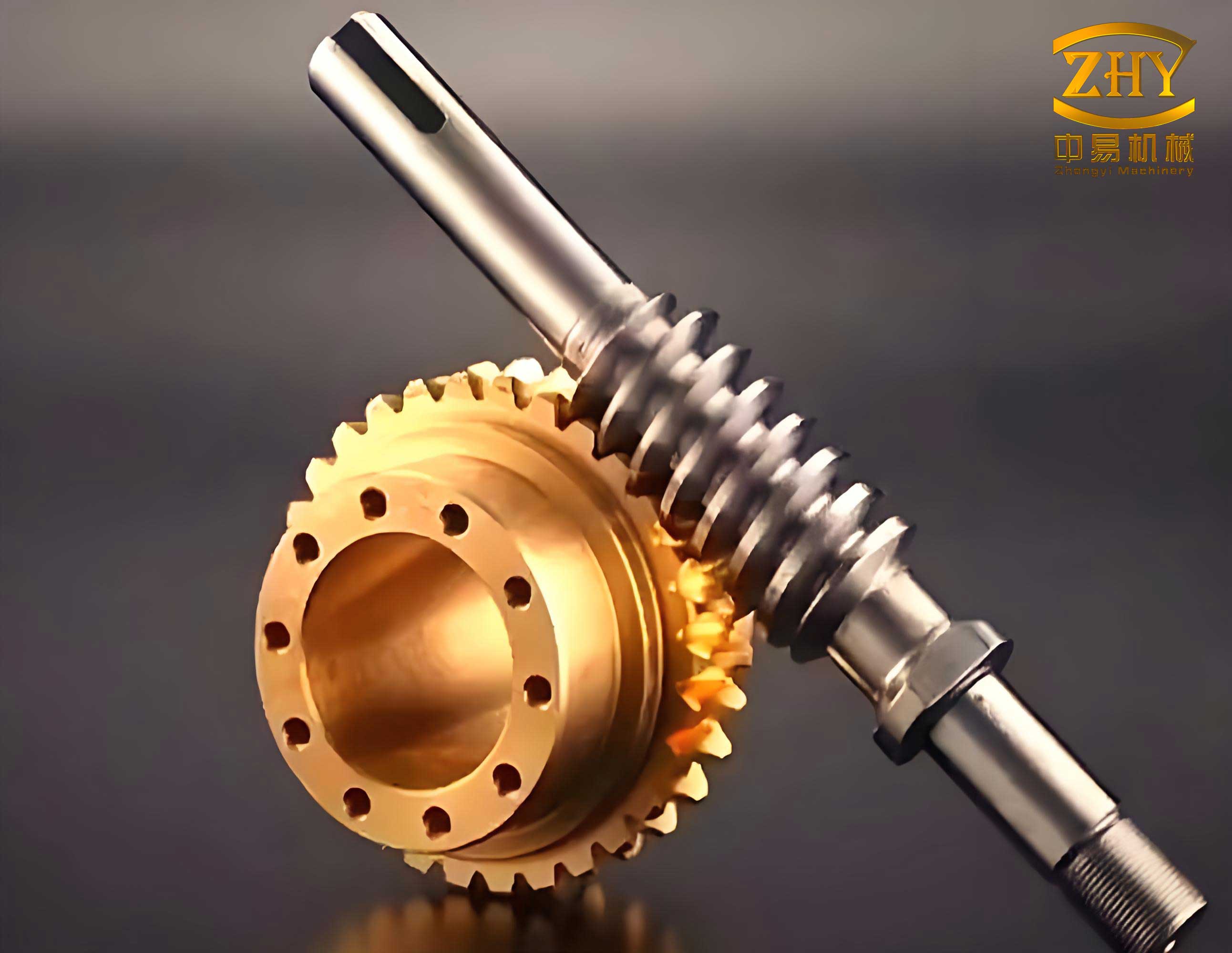
The core principle of parametric design lies in defining a set of driving parameters and establishing mathematical relationships between them and the final geometry. For a screw gear set, these driving parameters typically include the axial module (m), the number of threads on the worm (z1), the number of teeth on the worm wheel (z2), the diameter quotient (q), and the pressure angle (α). From these, all other geometrical features are derived. This parametric foundation allows for the creation of a single, intelligent model that can generate an entire family of screw gears. The process involves three key stages: parameter calculation based on standards and design requirements, structural design considerations, and the step-by-step construction of the 3D parametric model within CATIA.
Let us begin with the parametric design of the worm, which is the driving member in most screw gear applications. The worm is essentially a threaded shaft, and its geometry is governed by standard calculations. For this exposition, I will adopt a baseline set of parameters to illustrate the process: an axial module m = 2.5 mm, a single-threaded worm (z1 = 1), and a diameter quotient q = 12. The choice of q influences the worm’s stiffness and the efficiency of the screw gear pair. The following table summarizes the critical parameters and their derivations for the worm component.
| Parameter Name | Symbol | Calculation Formula | Result (mm or °) |
|---|---|---|---|
| Axial Pitch | p_x | $$p_x = \pi m$$ | 7.854 |
| Lead | p_z | $$p_z = z_1 \cdot p_x$$ | 7.854 |
| Lead Angle | γ | $$\gamma = \arctan\left(\frac{p_z}{\pi d_1}\right) = \arctan\left(\frac{z_1}{q}\right)$$ | 4.764° |
| Reference Diameter | d1 | $$d_1 = m \cdot q$$ | 30.0 |
| Tip Diameter | d_{a1} | $$d_{a1} = d_1 + 2m$$ | 35.0 |
| Root Diameter | d_{f1} | $$d_{f1} = d_1 – 2.4m$$ | 24.0 |
| Tooth Height | h | $$h = 2.2m$$ | 5.5 |
With these parameters defined, the structural design phase commences. A primary decision is the profile of the worm thread. While various types exist (such as involute or convolute), the ZA (Zerol bevel? Actually, Archimedean) or ZI (involute) profiles are common. For simplicity in modeling and calculation, an Archimedean profile, where the axial section tooth profile is a straight-sided rack, is often chosen. Another consideration is whether to fabricate the worm as a single piece with its shaft or as an assembly. If the root diameter is sufficiently larger than the required shaft diameter, an integral design is preferable for strength and simplicity. Machining considerations, such as the inclusion of thread relief grooves at both ends of the threaded section, must also be incorporated into the model’s features.
The parametric modeling process in CATIA for the worm starts with defining the listed parameters using the **Formulas** tool. Each parameter is created with a meaningful name, type (Length, Angle, etc.), and its value or formula. For instance, the parameter `Lead_Angle` would have the formula `=atan(Number_of_Threads / Diameter_Quotient)`. The 3D construction typically begins by sketching and revolving the basic shaft geometry, referencing the `Root_Diameter` and `Shaft_Length` parameters. The creation of the helical thread is the most critical step. This is achieved using the **Helix** function. The helix definition is driven by our parameters: its pitch is equal to the axial pitch `p_x`, its height is the worm’s threaded length, and its starting diameter is the reference diameter `d1`. The thread profile—a trapezoid defined by the module and pressure angle—is then sketched in a plane normal to the helix’s start point. Finally, the **Rib** or **Sweep** command is used to sweep this profile along the helical path, creating the solid thread. The beauty of parametrics is that altering `m` or `z1` will automatically update the helix pitch and the profile sketch, regenerating a perfectly correct new worm geometry. Features like relief grooves, keyways, and bearing seats are added subsequently, their dimensions also linked to the main parameters where appropriate.
The design of the mating worm wheel, the driven element of the screw gear pair, follows a complementary parametric process. Its geometry is inherently linked to that of the worm. Using our baseline set and specifying a worm wheel with z2 = 29 teeth, we can calculate its key dimensions. The calculation must account for the fact that the worm wheel is essentially a helical gear with a throat that wraps partially around the worm. The following table outlines these essential calculations for the worm wheel.
| Parameter Name | Symbol | Calculation Formula | Result (mm or °) |
|---|---|---|---|
| Reference Diameter | d2 | $$d_2 = m \cdot z_2$$ | 72.5 |
| Throat Diameter | d_{a2} | $$d_{a2} = d_2 + 2m$$ | 77.5 |
| Root Diameter | d_{f2} | $$d_{f2} = d_2 – 2.4m$$ | 66.5 |
| Outer Rim Diameter | d_{e2} | $$d_{e2} \leq d_{a2} + 1.5m \text{ (for z1=1)}$$ | 81.25 (e.g., 79.0) |
| Face Width | b2 | $$b_2 \leq 0.75 \cdot d_{a1}$$ | 26.25 (e.g., 25.0) |
| Helix Angle | β | $$\beta = \gamma$$ (for 90° shaft angle) | 4.764° |
Structurally, worm wheels are often designed with a bronze or brass rim mounted on a steel center, especially for power transmission, due to the different material requirements for wear resistance and strength. The parametric model can reflect this as an assembly. However, for a monolithic design, the wheel typically features a web with lightening holes or a spoke structure to reduce weight and material cost. The rim must be of sufficient width to ensure proper contact with the worm threads.
The parametric modeling of the worm wheel in CATIA presents a fascinating challenge: creating the helical, enveloping teeth. The tooth profile in the normal plane is an involute curve, but it must be swept along a helical path with a lead angle matching the worm’s. The first step is to model the blank—a cylindrical body with diameters equal to the throat and outer rim diameters. The next, and most complex, step is to generate a single tooth groove. This begins with defining the involute curve of the gear tooth. The parametric equations for an involute curve, based on the base circle radius \(r_b\), are fundamental:
$$
x = r_b (\cos(\phi) + \phi \sin(\phi))
$$
$$
y = r_b (\sin(\phi) – \phi \cos(\phi))
$$
where \(\phi\) is the roll angle in radians. In CATIA’s **Law** or **Formula** editor, this can be implemented using a parameter `t` ranging from 0 to 1 to define a segment of the involute. For a gear with pressure angle α, the base radius is \(r_b = \frac{m z_2 \cos(\alpha)}{2}\). This curve is sketched in the normal plane. The sweep path for this profile is a helix defined on the worm wheel’s reference cylinder. The pitch of this helix, \(P_{h}\), is crucial and is derived from the lead of the worm, but scaled to the wheel’s circumference: essentially, it is the lead of the equivalent helical gear on the wheel.
$$
P_{h} = \frac{\pi d_2}{\tan(\gamma)}
$$
Using this helical path, the involute profile is swept to cut a single tooth space into the blank. Finally, the **Circular Pattern** feature is used to create the total number of teeth, `z2`, around the axis. All these features—the diameters, the involute formula coefficients, the helix pitch, and the number of instances in the pattern—are driven by the primary parameters (`m`, `z2`, `α`, `γ`). Therefore, generating a new screw gear wheel for a different ratio only requires updating these few driving values; CATIA handles the complete geometric regeneration automatically.
The true power of this parametric approach extends beyond individual parts to the assembly and interaction of the screw gear pair. In CATIA, the worm and worm wheel can be assembled using constraints that are also parametrically aware. The center distance `a`, a critical assembly parameter, is calculated as:
$$
a = \frac{m(q + z_2)}{2}
$$
This value can be stored as a parameter in the assembly context and used to position the axes of the two components. Furthermore, with the use of CATIA’s **DMU Kinematics** module, the parametric screw gear assembly can be transformed into a functional mechanism. Joints are defined (a revolution joint for the worm, another for the wheel, coupled with a screw joint defining the transmission ratio), allowing for dynamic simulation of the engagement. This enables virtual checks for interference, analysis of the contact path, and validation of the assembly’s kinematic behavior long before any physical prototype is built. It provides irrefutable verification that the parametrically derived geometries of the screw gear mesh correctly.
In conclusion, the adoption of a fully parametric design methodology for screw gears within the CATIA environment represents a significant advancement in mechanical design efficiency and accuracy. This process transforms the design from a static, one-off modeling task into a dynamic, rule-driven system. The advantages are multifold: it ensures consistency across all derived dimensions, eliminates manual calculation errors during model updates, facilitates the creation of standardized component libraries for an organization, and dramatically accelerates the design cycle for custom gear requirements. The screw gear, a classic and vital power transmission element, is perfectly suited to benefit from such an approach. By embedding engineering intelligence and design intent directly into the 3D model, CATIA’s parametric tools empower designers to create more reliable, optimized, and adaptable screw gear systems, solidifying its role as a cornerstone technology in modern mechanical engineering and manufacturing.