
As a mechanical engineer focused on maritime applications, I have often analyzed the critical safety systems onboard vessels. The anchoring operation is a fundamental yet potentially hazardous procedure. When a ship arrives at a port, it frequently must anchor at a designated anchorage area to await a berth, receive pilots or quarantine, shelter from weather, or conduct lightering operations. For this purpose, ships rely on anchor handling winches—electric, hydraulic, or electro-hydraulic—to lower the anchor and achieve braking, thereby keeping the vessel stationary. However, under the influence of wind, waves, and currents, the anchor chain can be subjected to substantial tensile forces. In such conditions, the conventional braking mechanisms between the chain wheel, drive shaft, and drum may prove inadequate, allowing the chain to pay out further. This uncontrolled release increases the vessel’s swinging radius, creating a significant risk of grounding or collision with other anchored vessels.
To prevent this hazardous chain release, it is essential to apply an additional restraining force on the chain wheel to counterbalance sudden external loads. In this design exploration, I leverage the fundamental self-locking principle inherent in screw gear (worm gear) transmission systems and introduce significant enhancements. The core innovation involves applying a novel screw gear self-locking device to the anchor chain wheel, ensuring reliable braking. The improvements are twofold. Firstly, utilizing a screw gear transmission mechanism inherently provides a high reduction ratio, which is beneficial for tightening the anchor chain and retrieving the anchor fluke. Secondly, the essence of this new device is a dual-worm configuration coupled with a PLC (Programmable Logic Controller) monitoring system. This combination offers superior self-locking reliability and enables precise control over the length of chain deployed or retrieved. Such precision is crucial for standardizing a vessel’s position within a crowded port anchorage and maximizing the efficient use of available space.
Fundamentals and Limitations of Conventional Screw Gear Self-Locking
A traditional screw gear speed reducer is composed of the meshing screw gear pair, shafts, bearings, a housing, and ancillary components. Its primary function is as a power transmission mechanism, using the gear speed converter to reduce the high-speed rotation of an electric motor to the desired output speed while achieving a substantial multiplication of torque, often by factors of hundreds. The self-locking condition for a screw gear drive is a classic topic in machine design. It occurs when the gear (worm wheel) becomes the driving member and the screw (worm) the driven member, and the system resists back-driving. The condition is mathematically expressed by the relationship between the lead angle of the worm ($$ \gamma $$) and the equivalent angle of friction ($$ \rho $$):
$$ \gamma < \rho $$
This principle is analogous to an object resting on an inclined plane, which will not slide down if the angle of the plane is less than the arctangent of the coefficient of static friction. The self-locking capability is therefore intimately tied to the friction conditions at the meshing interface. For different gear materials, the equivalent friction angle varies, dictating the maximum permissible lead angle for self-locking. For instance, common values are:
| Equivalent Coefficient of Friction (μ) | Equivalent Friction Angle (ρ) | Maximum Worm Lead Angle (γ) for Self-Lock |
|---|---|---|
| 0.6 | ~30.96° | < 3° 29′ 11″ |
| 0.7 | ~34.99° | < 4° 03′ 57″ |
| 0.8 | ~38.66° | < 4° 38′ 39″ |
While this table illustrates the theoretical relationship, several practical issues plague the reliability of conventional screw gear self-locking in harsh marine environments:
- Frictional Losses and Efficiency: Screw gear drives are inherently less efficient than other gear forms due to significant sliding friction at the tooth contact. When acting as a transmission (worm driving the wheel), these losses are accepted for the sake of high reduction. However, in a self-locking scenario, these same frictional losses mean the actual operating coefficient of friction is dynamic. If the effective friction decreases due to lubrication or wear, the condition $$ \gamma < \rho $$ may no longer hold, leading to self-lock failure.
- Lubrication State Dependency: The coefficient of friction is highly sensitive to the lubrication regime. The presence of an oil film can reduce friction, effectively increasing the required lead angle for self-locking and destabilizing the system’s equilibrium. Maintaining a consistent, optimal lubrication state in a marine setting is challenging.
- Vibration-Induced Transitions: The complex motion of a ship at sea subjects all machinery to vibrations. Such vibrations can cause transitions between static and dynamic friction at the screw gear interface. Since the dynamic coefficient of friction is generally lower than the static one, vibration can abruptly degrade the self-locking performance, potentially causing a “creep” or sudden release.
These limitations underscore the need for a more robust and controllable self-locking solution for critical applications like anchor chain arrest. The conventional single screw gear arrangement is often insufficiently reliable under variable and severe operating conditions.
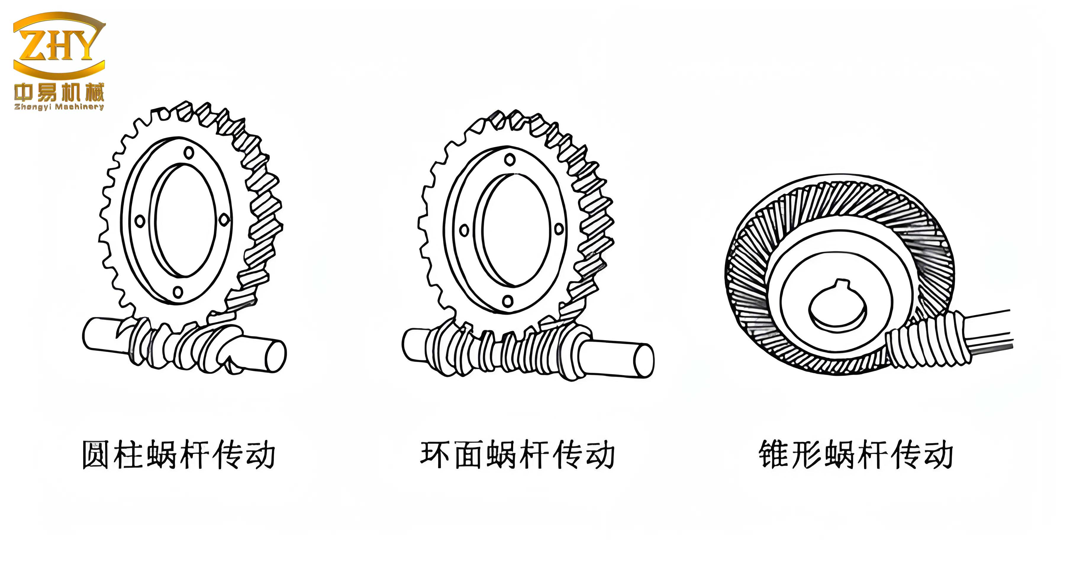
Design and Operation of the Novel Marine Screw Gear Self-Locking Device
Design Requirements Analysis
The primary design objective is to prevent unintended anchor chain release. This is achieved by integrating an adjustable-ratio screw gear self-locking device, augmented with a PLC-based signal monitoring system, onto the shaft of the anchor chain wheel. The device must meet several key specifications derived from marine standards and practical needs:
- The screw gear pair must be designed for reliable self-locking, typically requiring a worm with a module (m) near 15 mm and a single-start thread to achieve a small lead angle.
- To address lubrication challenges autonomously, an automated, PLC-controlled oil-mist or drip lubrication system should be incorporated.
- The driving electric motor must conform to standard marine power ratings, with a designed power (P) between 30 kW and 50 kW to handle the loads specified by anchor chain standards.
- The entire system must withstand the maximum proof load of the selected anchor chain. For example, following standards like GB/T 549-2017, an AM3 grade chain has a specified proof load. The device must generate a restraining torque greater than the torque induced by this load on the chain wheel.
- The PLC monitoring must provide real-time feedback, with sensors capable of detecting chain movement with high precision (e.g., per shot of chain, approximately 27.5 m) to enable accurate positioning.
System Architecture and Working Principle
The novel self-locking device comprises three integrated subsystems: the dual-worm screw gear transmission mechanism, the PLC-based control and locking system, and an automated lubrication system. Its operation can be understood in two main modes: the powered retrieval (drive) mode and the self-locking (hold) mode.
1. Powered Retrieval Mode (Worm as Driver): In this state, the anchor is on the seabed. The system activates to recover the anchor. An electric motor provides input power. A key innovation is the use of an electromagnetic clutch and a synchronizer gearbox preceding the screw gear input. The PLC receives signals from a position sensor (monitoring anchor fluke angle) and a rotary encoder on the gearbox. Based on the required retrieval speed and tension, the PLC commands the electromagnetic clutch to engage either a single-stage or multi-stage input from the gearbox. The synchronizer allows smooth ratio changes within the gearbox. This enables the system to provide a high reduction ratio (e.g., 80:1) initially for breaking out the anchor from the seabed and a lower ratio for faster retrieval once the chain is vertical. The output from this variable-speed drive turns the primary worm. This worm, meshing with the large screw gear (worm wheel) attached to the chain wheel, provides the high torque needed to haul in the chain.
2. Self-Locking Hold Mode (Gear as Driver): Once the anchor is secured home in the hawsepipe or the desired chain length is deployed, the system switches to locking mode. The position sensor signals the PLC that the target is reached. The PLC first commands the gearbox synchronizer to shift to its lowest effective ratio (e.g., 30:1), slowing the input. Finally, it disengages the electromagnetic clutch, cutting mechanical power to the worm shaft. However, the chain wheel and its attached screw gear may still be subject to transient forces from vessel movement. In a conventional system, this load would try to back-drive the single worm. In this novel design, the dual-worm configuration comes into play. The primary worm is now mechanically locked via the clutch. A second, symmetrically opposed worm, also meshing with the same screw gear but not connected to the motor drive, acts as an immediate passive locking brake. The load from the gear is distributed across two worm interfaces, effectively doubling the frictional resistance to back-driving and providing a far more reliable lock. The condition for self-locking must hold for both worms: $$ \gamma < \rho_1 $$ and $$ \gamma < \rho_2 $$, where the subscripts denote the potentially different friction conditions at each mesh, though design aims to make them equal.
Key Component Descriptions
- Electromagnetic Clutch: A fixed-coil type clutch with two driven connection points. It allows the PLC to instantly connect or disconnect the motor/gearbox assembly from the worm shaft, facilitating the shift between drive and lock modes.
- Synchronizer Gearbox: An intermediate gearbox with inertia-type synchronizers. It allows the PLC to select different reduction ratios between the motor and the worm shaft, optimizing torque and speed for different phases of the anchor handling operation (e.g., breaking out, hoisting, final positioning).
- PLC Control Module: The system’s brain. It integrates a central processing unit, memory, I/O modules, and communication ports. It continuously processes signals from all sensors (position, speed, oil level, etc.) and sends command outputs to the clutch, gearbox solenoids, and lubrication pump.
- Sensor Suite: Includes a rotary encoder on the gearbox output for speed/position feedback, a position sensor (e.g., potentiometric or encoder-based) to track the anchor’s state, oil level sensors in the lubrication reservoir, and an oil mist sensor in the screw gear housing to monitor lubrication effectiveness.
- Automated Lubrication System: Consists of a reservoir, pump, solenoid valve, and spray nozzles directed at the worm-gear meshes. The PLC activates lubrication cycles based on runtime, sensor feedback (e.g., low oil mist density), or during specific high-load operations to ensure the friction coefficient (ρ) remains stable and favorable for self-locking.
Detailed Selection and Design Calculations for the Screw Gear System
Torque Requirement at the Screw Gear Shaft
The design starts with the load. Selecting an AM3-24 anchor chain per standard, its proof load is \( F_{\text{proof}} = 332 \text{ kN} \). The weight of the chain itself in water must be considered. For a 6-shots length (\( L = 6 \times 27.5 \text{ m} = 165 \text{ m} \)) and a mass per meter of \( 12.61 \text{ kg/m} \), the submerged weight (assuming a buoyancy factor) contributes to the tension. The total maximum restraining force \( F_{\text{max}} \) is the vector sum of proof load and chain weight. The torque \( T_1 \) that the screw gear shaft must resist is:
$$ T_1 = F_{\text{max}} \times r_{\text{chain\_wheel}} $$
Where \( r_{\text{chain\_wheel}} \) is the effective radius of the chain wheel. For a sample calculation, assuming a combined load and radius yielding \( T_1 = 55,110 \text{ N·mm} \).
Screw Gear Pair Design and Verification
Given the high load and marine environment, an open-type screw gear drive is chosen to avoid complex sealing. Materials are selected for wear resistance and compatibility: the worm is made from 20Cr steel, case-hardened to 58-63 HRC; the screw gear is cast from tin bronze ZCuSn5Pb5Zn5. The design proceeds with verification calculations.
1. Design Parameters and Assumptions:
- Desired gear ratio: \( i = 50 \).
- Worm number of starts: \( z_1 = 1 \) (for potential self-locking and high ratio).
- Gear number of teeth: \( z_2 = i \times z_1 = 50 \).
- Estimated efficiency (for initial torque calc): \( \eta \approx 0.65 \).
- Application factor: \( K_A = 1.4 \) (moderate shock).
- Allowable contact stress for bronze gear: \( [\sigma_H] = 200 \text{ MPa} \).
- Allowable bending stress for gear: \( [\sigma_F] = 32 \text{ MPa} \).
- Elastic coefficient: \( Z_E = 150 \sqrt{\text{MPa}} \) (steel-bronze pair).
2. Torque on Screw Gear:
$$ T_2 = T_1 \times \eta \times i = 55,110 \times 0.65 \times 50 = 1,791,075 \text{ N·mm} $$
3. Preliminary Center Distance based on Contact Strength:
The formula for center distance \( a \) is:
$$ a \geq \sqrt[3]{K_A T_2 \left( \frac{Z_E Z_\rho}{[\sigma_H]} \right)^2 } $$
Assuming a contact coefficient \( Z_\rho = 2.8 \) for \( d_1 / a \approx 0.4 \):
$$ a \geq \sqrt[3]{1.4 \times 1.791 \times 10^6 \times \left( \frac{150 \times 2.8}{200} \right)^2 } \approx 211.6 \text{ mm} $$
4. Module and Geometry Selection:
An estimated worm diameter: \( d_1 \approx 0.68 a^{0.875} \approx 73.7 \text{ mm} \).
Tentative module: \( m = \frac{2a – d_1}{z_2} = \frac{2\times211.6 – 73.7}{50} \approx 6.99 \text{ mm} \).
Referring to standard modules and diameter factors, we select: \( m = 8 \text{ mm} \), \( q = 17.5 \), therefore:
$$ d_1 = q \cdot m = 17.5 \times 8 = 140.0 \text{ mm} $$
$$ d_2 = z_2 \cdot m = 50 \times 8 = 400.0 \text{ mm} $$
$$ a = 0.5m(q + z_2) = 0.5 \times 8 \times (17.5 + 50) = 270.0 \text{ mm} > 211.6 \text{ mm} \quad \text{(OK)} $$
5. Lead Angle and Self-Locking Check:
$$ \gamma = \arctan\left(\frac{z_1}{q}\right) = \arctan\left(\frac{1}{17.5}\right) \approx 3.27^\circ $$
This lead angle is well below typical friction angles for bronze on steel (often \( \rho > 5^\circ \)), confirming a strong inherent self-locking tendency for the gear pair in a static, well-lubricated state.
6. Bending Strength Verification of Gear Teeth:
The virtual number of teeth: \( z_{v2} = \frac{z_2}{\cos^3 \gamma} \approx 50 \). From which the tooth form factor \( Y_{Fa2} \approx 2.35 \).
Bending stress:
$$ \sigma_F = \frac{1.53 K_A T_2}{d_1 d_2 m \cos \gamma} Y_{Fa2} = \frac{1.53 \times 1.4 \times 1.791\times10^6}{140 \times 400 \times 8 \times \cos 3.27^\circ} \times 2.35 \approx 17.2 \text{ MPa} $$
Since \( \sigma_F < [\sigma_F] = 32 \text{ MPa} \), the design is safe against bending.
7. Worm Shaft Stiffness Check:
Excessive deflection of the worm can cause poor meshing and affect self-locking. The worm length between bearings: \( l \approx 0.9 d_2 = 360 \text{ mm} \).
Forces on the worm:
Tangential force on gear (equals axial on worm): \( F_{t2} = \frac{2T_2}{d_2} = 8,955.4 \text{ N} \).
Radial force (separating): \( F_r \approx F_{t2} \cdot \tan(20^\circ) = 3,259.5 \text{ N} \).
Moment of inertia of worm section: \( I = \frac{\pi d_1^4}{64} = 1.886 \times 10^7 \text{ mm}^4 \).
Modulus of Elasticity for steel: \( E = 2.06 \times 10^5 \text{ MPa} \).
The maximum deflection at the center, combining bending from radial and axial (treated as radial due to 90° mesh) forces, is:
$$ y = \sqrt{ \left( \frac{F_r l^3}{48 E I} \right)^2 + \left( \frac{F_{t2} l^3}{48 E I} \right)^2 } \approx 0.0023 \text{ mm} $$
The allowable deflection is typically \( [y] = 0.001 \times d_1 = 0.14 \text{ mm} \). Since \( y \ll [y] \), stiffness is more than adequate.
Motor Power Selection
The minimum required motor power is determined by the input torque \( T_1 \) and the required worm speed \( n_1 \). For retrieval, a worm speed of \( n_1 = 1000 \text{ rpm} \) might be targeted.
$$ P_{\text{min}} = \frac{T_1 \cdot n_1}{9.55 \times 10^6} = \frac{55,110 \times 1000}{9.55 \times 10^6} \approx 5.8 \text{ kW} $$
This is the mechanical power needed at the worm shaft. Accounting for losses in the gearbox, clutch, and bearings, and providing a safety/performance margin, a standard marine motor like the Y160M-6, rated at 7.5 kW with a full-load speed of 970 rpm, would be a suitable selection. Its speed can be managed via the variable-ratio gearbox to achieve the desired worm input speed.
Conclusion and Future Directions
This design study presents a comprehensive approach to enhancing the reliability of anchor chain braking through a novel screw gear self-locking mechanism. The analysis of conventional screw gear systems highlighted their vulnerability to changing friction conditions, lubrication states, and vibration—all prevalent in the marine environment. In response, the proposed design integrates a dual-worm screw gear configuration for redundant locking, a PLC-controlled automation system for precise operation and monitoring, and an automated lubrication system to maintain optimal friction characteristics.
The detailed design and verification calculations confirm the feasibility of the screw gear pair to handle the significant loads imposed by standard anchor chains while maintaining a lead angle conducive to reliable self-locking. The incorporation of a variable-ratio input gearbox and an electromagnetic clutch allows the system to function optimally both as a high-torque retrieval winch and a fail-safe locking device.
While this screw gear-based design offers a significant theoretical advancement, further research and development are warranted. Future work should focus on:
- Dynamic modeling and testing of the dual-worm interaction under shock loads and high vibration to fully validate the redundancy benefit.
- Optimization of the PLC control algorithms, particularly for the synchronization of lubrication cycles with load events to maximize screw gear mesh life and locking reliability.
- Development and testing of a full-scale prototype under simulated and real marine conditions to identify any unforeseen practical challenges.
- Exploration of advanced materials or surface treatments for the screw gear pair to further stabilize the coefficient of friction and enhance wear resistance in a saltwater environment.
By addressing the inherent weaknesses of traditional systems through integrated mechanical and control design, this novel screw gear self-locking device represents a promising direction for improving the safety and operational precision of marine anchoring systems.