
In the field of mechanical power transmission, the worm drive, a type of screw gear, has been extensively utilized due to its remarkable advantages, including high load capacity, large reduction ratio within a single stage, compact structural design, and smooth, quiet operation. However, conventional worm gear pairs predominantly rely on sliding contact between the conjugated tooth surfaces. This inherent sliding action often leads to significant drawbacks such as substantial friction losses, excessive heat generation, pronounced wear, and a heightened risk of scoring failure, ultimately constraining their transmission efficiency and service life in demanding applications. The pursuit of higher performance and reliability has driven continuous innovation in screw gear design.
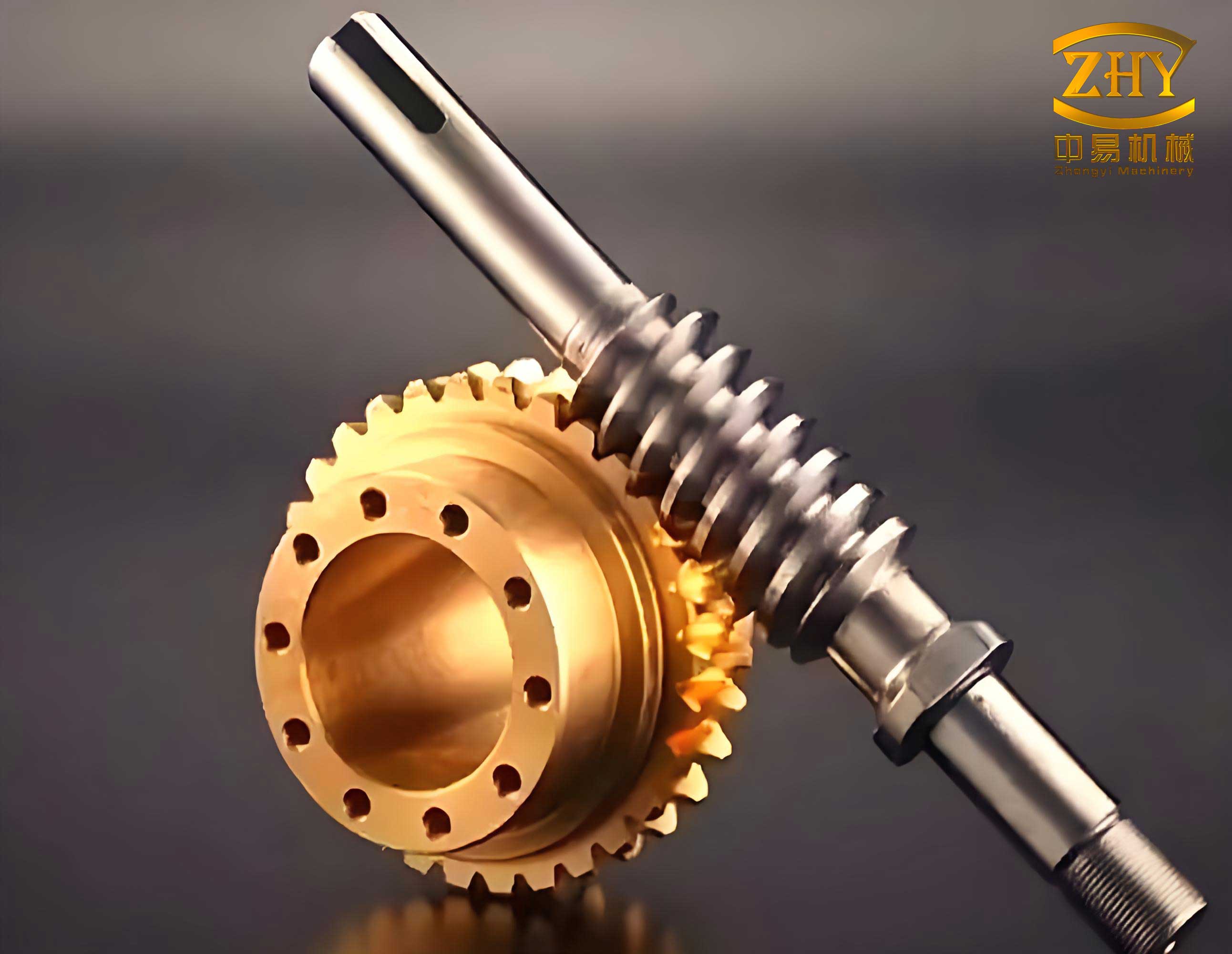
Building upon the foundation of tapered roller enveloping hourglass worm drives, this work introduces a novel variant: the cosine roller enveloping hourglass worm drive. The core innovation lies in modifying the generating geometry. Instead of a conventional tapered roller with a straight-line generatrix, the proposed design employs a roller whose working surface is generated by revolving a cosine curve about its axis. This specific screw gear configuration aims to fundamentally alter the contact kinematics. The rollers are mounted on the worm wheel and can rotate freely about their own axes. During meshing, the primary motion is transferred from the enveloping worm to the wheel via these rollers. Crucially, the contact between the worm thread and the roller surface can induce rolling motion of the rollers, thereby potentially converting a significant portion of the detrimental sliding friction into more favorable rolling friction. This transformation is anticipated to yield superior performance characteristics, including reduced wear, lower operating temperatures, and enhanced transmission efficiency. This analysis delves into the meshing theory, establishes a rigorous mathematical model, derives key performance metrics, and systematically compares its performance against the conventional tapered roller design, paving the way for its optimal design and application.
Mathematical Modeling of the Meshing Principle
The accurate analysis of any screw gear system begins with a precise mathematical description of its geometry and kinematics. For the cosine roller enveloping worm drive, we establish coordinate systems based on the theory of gearing and differential geometry.
Coordinate Systems and Surface Equation
The spatial relationship between the worm and the worm wheel is defined using several coordinate systems. Let $S_1′(O_1′; \mathbf{i}_1′, \mathbf{j}_1′, \mathbf{k}_1′)$ and $S_2′(O_2′; \mathbf{i}_2′, \mathbf{j}_2′, \mathbf{k}_2′)$ represent the fixed coordinate systems attached to the worm and wheel frames, respectively. The rotating coordinate systems attached to the worm and wheel are denoted as $S_1(O_1; \mathbf{i}_1, \mathbf{j}_1, \mathbf{k}_1)$ and $S_2(O_2; \mathbf{i}_2, \mathbf{j}_2, \mathbf{k}_2)$. The worm’s rotation angle is $\phi_1$ with angular velocity $\omega_1$, and the wheel’s rotation angle is $\phi_2$ with angular velocity $\omega_2$. The gear ratio is $i_{12} = \omega_1 / \omega_2 = \phi_1 / \phi_2$. The center distance is denoted by $A$. When $\phi_1 = \phi_2 = 0$, the rotating frames coincide with their respective fixed frames.
A local coordinate system $S_0(O_0; \mathbf{i}_0, \mathbf{j}_0, \mathbf{k}_0)$ is established at the top of the roller’s axis, where point $O_0$ has coordinates $(a_2, 0, 0)$ in $S_2$. At the potential contact point $O_p$ on the roller, a moving frame $S_p(O_p; \mathbf{e}_1, \mathbf{e}_2, \mathbf{n})$ is set up, where $\mathbf{n}$ is the unit normal to the roller surface, $\mathbf{e}_1$ is along the tangent to the roller’s profile, and $\mathbf{e}_2$ is perpendicular to $\mathbf{e}_1$ within the tangent plane.
The surface of the cosine roller in its local frame $S_0$ is defined by two parameters: a length parameter $u$ and an angular parameter $\theta$. Its vector equation is:
$$\mathbf{r}_0 = x_0 \mathbf{i}_0 + y_0 \mathbf{j}_0 + z_0 \mathbf{k}_0$$
where the coordinates are given by:
$$
\begin{aligned}
x_0 &= R \cos\theta, \\
y_0 &= R \sin\theta, \\
z_0 &= u.
\end{aligned}
$$
The key feature is the definition of the radius $R$, which varies with $u$ according to a cosine law:
$$ R = a_{u1} \arccos(a_{u2}).$$
The coefficients $a_{u1}$ and $a_{u2}$ are defined as:
$$ a_{u1} = \frac{2R_1}{\pi}, \quad a_{u2} = \frac{u_1 – u}{u_1} \cos\left(\frac{R_2 \pi}{2R_1}\right).$$
Here, $u_1$ is the total tooth height, $R_1$ is the radius at the large end of the roller, $R_2$ is the radius at the small end of the roller, $m$ is the module, $h_{ac}^*$ is the addendum coefficient, $h_{fc}^*$ is the dedendum coefficient, $c^*$ is the clearance coefficient, $k$ is the throat diameter coefficient, and $Z_2$ is the number of teeth on the worm wheel. The total height and module are calculated as:
$$ u_1 = m(h_{ac}^* + h_{fc}^* + c^*), \quad m = \frac{(2 – k)A}{Z_2}.$$
This formulation distinguishes this screw gear from its tapered counterpart, where $R$ is a linear function of $u$.
Coordinate Transformations and Relative Velocity
The transformation from the worm coordinate system $S_1$ to the wheel coordinate system $S_2$ is essential for meshing analysis. The relationship is given by $\mathbf{Q}_2 = \mathbf{M}_{21} \mathbf{Q}_1$, where $\mathbf{M}_{21}$ is a 4×4 homogeneous transformation matrix derived from successive rotations and translations involving $\phi_1$, $\phi_2$, and $A$.
The transformation between the wheel system $S_2$ and the contact point moving frame $S_p$ is described by a rotation matrix $\mathbf{A}_{p2}$:
$$
\mathbf{A}_{p2} = \begin{pmatrix}
0 & \cos\theta & -\sin\theta \\
-\cos\beta & \sin\beta \sin\theta & \sin\beta \cos\theta \\
\sin\beta & \cos\beta \sin\theta & \cos\beta \cos\theta
\end{pmatrix}.
$$
Here, $\beta$ is the angle between vector $\mathbf{e}_2$ and the roller axis $\mathbf{k}_0$, calculated from the roller geometry:
$$ \beta = \frac{\pi}{2} – \arctan(T_\beta), \quad T_\beta = -\omega_u A_u \sin(\omega_u R),$$
with $\omega_u = \pi/(2R_1)$ and $A_u = -u_1 / \cos(\omega_u R_2)$.
The relative velocity vector $\mathbf{v}_{12}$ at the contact point, expressed in the moving frame $S_p$, is the fundamental kinematic quantity. For this fixed-center screw gear, it is derived as $\mathbf{v}_{12} = \boldsymbol{\omega}_{12} \times \mathbf{r}_1$, where $\boldsymbol{\omega}_{12} = \boldsymbol{\omega}_1 – \boldsymbol{\omega}_2$ is the relative angular velocity. Its components are:
$$
\begin{aligned}
v_{12}^{(1)} &= B_2 \cos\theta – B_3 \sin\theta, \\
v_{12}^{(2)} &= B_3 \sin\beta \cos\theta – B_1 \cos\beta + B_2 \sin\beta \sin\theta, \\
v_{12}^{(n)} &= B_1 \sin\beta + B_3 \cos\beta \cos\theta + B_2 \cos\beta \sin\theta,
\end{aligned}
$$
where $B_1, B_2, B_3$ are functions of the coordinates in $S_2$, the angular velocities, and the center distance.
Meshing Equation and Worm Thread Surface
According to the fundamental theorem of conjugate surfaces, meshing occurs at points where the relative velocity has no component along the common normal to the surfaces. This condition is the meshing equation:
$$ \Phi = \mathbf{v}_{12} \cdot \mathbf{n} = v_{12}^{(n)} = 0.$$
Substituting the expression for $v_{12}^{(n)}$ leads to the specific meshing function for this drive:
$$ \Phi = M_1 \cos\phi_2 + M_2 \sin\phi_2 + M_3 = 0,$$
where $M_1, M_2,$ and $M_3$ are functions of the roller surface coordinates $(x_2, y_2, z_2)$ in $S_2$, the angles $\beta$ and $\theta$, and the gear parameters $i_{21}$ and $A$.
The thread surface of the enveloping worm is the family of roller surfaces in the worm coordinate system $S_1$, subjected to the meshing condition. Therefore, the worm thread surface $\mathbf{r}_1$ is given by the system of equations:
$$ \mathbf{r}_1 = \mathbf{M}_{12} \mathbf{r}_2, \quad \Phi(\mathbf{r}_2, \phi_2) = 0.$$
Here, $\mathbf{M}_{12}$ is the inverse transformation of $\mathbf{M}_{21}$, and $\mathbf{r}_2$ is the position vector of the roller surface point in $S_2$, obtained from $\mathbf{r}_0$ via a simple translation. The parameter $\theta$ becomes a function of $u$ and $\phi_2$ through the meshing equation: $\theta = \arctan(P_1 / P_2)$, with $P_1$ and $P_2$ being specific functions. The rotation angle $\phi_2$ typically varies over the engagement cycle, e.g., from $-36^\circ$ to $36^\circ$.
Meshing Performance Analysis and Derivations
The performance of a screw gear is critically assessed through several key meshing characteristics. These parameters determine the contact stress, lubrication conditions, wear resistance, and overall efficiency of the drive.
Induced Normal Curvature
The induced normal curvature $k_\sigma^{(12)}$ along the direction of the relative velocity is a measure of the local conformity between the two contacting surfaces. A lower absolute value indicates better conformity, leading to lower contact stresses and improved load distribution. For the cosine roller screw gear, it is derived using the fundamental relations from the theory of gearing:
$$ k_\sigma^{(12)} = -\frac{H_1 + H_2}{\Psi}.$$
The terms $H_1$, $H_2$, and $\Psi$ are comprehensive functions involving the relative velocity components, the derivative of the meshing function $\Phi_t$, the normal curvatures ($k_1$, $k_2$) and geodesic torsion ($\tau_{g1}$) of the roller surface in the principal directions:
$$
\begin{aligned}
H_1 &= (v_{12}^{(1)} k_1 + v_{12}^{(2)} \tau_{g1} + \omega_{12}^{(2)})^2, \\
H_2 &= (v_{12}^{(2)} k_2 + v_{12}^{(1)} \tau_{g1} – \omega_{12}^{(1)})^2, \\
\Psi &= \Phi_t + \omega_{12}^{(2)} v_{12}^{(1)} – \omega_{12}^{(1)} v_{12}^{(2)} + k_1 (v_{12}^{(1)})^2 + k_2 (v_{12}^{(2)})^2 + 2\tau_{g1} v_{12}^{(1)} v_{12}^{(2)}.
\end{aligned}
$$
The normal curvatures for the cosine roller are $k_1 = -\cos\beta / R$ and $k_2 = -u” / (1 + (u’)^2)^{3/2}$, where $u’$ and $u”$ are the first and second derivatives of $u$ with respect to $R$ from the cosine relation $R(u)$.
Lubrication Angle
The lubrication angle $\mu$ is defined as the acute angle between the relative velocity vector $\mathbf{v}_{12}$ and the tangent vector $\mathbf{e}_t$ to the instantaneous contact line. It significantly influences the formation of a hydrodynamic lubricant film. A larger lubrication angle (closer to $90^\circ$) promotes better entrainment of lubricant into the contact zone. It is calculated as:
$$ \mu = \arcsin\left| \frac{v_{12}^{(1)}(v_{12}^{(1)}/R – \omega_{12}^{(2)}) + v_{12}^{(2)} \omega_{12}^{(1)}}{\sqrt{(v_{12}^{(1)}/R – \omega_{12}^{(2)})^2 + (\omega_{12}^{(1)})^2} \sqrt{(v_{12}^{(1)})^2 + (v_{12}^{(2)})^2}} \right|.$$
Entrainment Velocity
The entrainment velocity $v_{jx}$ is the average of the two surface velocities in the direction normal to the contact line. It is a primary factor in elastohydrodynamic lubrication (EHL), governing the thickness of the lubricant film. A higher entrainment velocity generally leads to a thicker protective film, reducing wear and friction. The surface velocities of the worm and roller in the normal direction are projected and averaged:
$$ v_{jx} = \frac{v_\sigma^{(1)} + v_\sigma^{(2)}}{2},$$
where
$$ v_\sigma^{(1,2)} = \frac{v_{1,2}^{(1)}(v_{12}^{(1)}/R – \omega_{12}^{(2)}) + v_{1,2}^{(2)} \omega_{12}^{(1)}}{\sqrt{(v_{12}^{(1)}/R – \omega_{12}^{(2)})^2 + (\omega_{12}^{(1)})^2}}.$$
Here $v_{1,2}^{(1)}$ and $v_{1,2}^{(2)}$ are the tangential velocity components of the worm and roller surfaces, respectively.
Roller Autorotation Angle
The autorotation angle $\mu_{z0}$ characterizes the tendency of the roller to spin about its own axis. It is the angle between the relative velocity vector $\mathbf{v}_{12}$ and the plane perpendicular to the roller’s axis (i.e., the component that causes rolling). An autorotation angle close to $90^\circ$ implies the relative velocity is almost perfectly aligned to cause pure rolling, which is ideal for minimizing sliding friction on the roller surface. It is computed simply from the relative velocity components:
$$ \mu_{z0} = \arccos\left| \frac{v_{12}^{(2)}}{\sqrt{(v_{12}^{(1)})^2 + (v_{12}^{(2)})^2}} \right|.$$
Performance Comparison and Parametric Study
To evaluate the advantages of the cosine roller design, a comparative analysis against the conventional tapered roller screw gear is conducted using the derived models. Furthermore, the influence of key geometric parameters on the meshing performance is investigated.
Comparative Analysis: Cosine vs. Tapered Roller Drives
Using a consistent set of parameters (Center distance $A=140$ mm, Worm threads $Z_1=1$, Wheel teeth $Z_2=25$, Throat coefficient $k=0.3$, Small end radius $R_2=5.5$ mm), the performance of both drives was simulated over the meshing cycle.
| Performance Metric | Cosine Roller Drive | Tapered Roller Drive | Observations and Implications |
|---|---|---|---|
| Induced Normal Curvature ($k_\sigma^{(12)}$) | Varies smoothly around ~0.02 mm⁻¹. | Exhibits larger fluctuations, up to ~0.07 mm⁻¹. | The cosine profile provides more stable and significantly lower contact curvature. This indicates superior contact conformity, leading to lower Hertzian contact stresses and potentially higher load capacity and fatigue life for this screw gear. |
| Lubrication Angle ($\mu$) | Slightly smaller (~1°) near the entry, converges at exit. | Slightly larger near the entry. | The difference is marginal. The change in roller profile does not substantially alter the kinematic direction of sliding relative to the contact line in this screw gear configuration. |
| Entrainment Velocity ($v_{jx}$) | Higher overall, minimum ~20 mm/s at throat. | Lower overall, minimum ~10 mm/s at throat. | A major advantage. The cosine profile approximately doubles the entrainment velocity. This dramatically improves the conditions for forming a full EHL film, greatly enhancing lubrication effectiveness and reducing the risk of boundary lubrication and wear. |
| Autorotation Angle ($\mu_{z0}$) | Slightly smaller (~0.5°) near the entry, converges at exit. | Slightly larger near the entry. | The difference is negligible. Both designs promote very high autorotation angles (>>85°), ensuring that the dominant motion at the roller contact is rolling, which is the core benefit of this class of screw gear. |
Conclusion: The cosine roller enveloping worm drive demonstrates a clear performance enhancement over the tapered roller design, primarily through a significant improvement in induced curvature (better contact) and entrainment velocity (better lubrication), while maintaining the excellent rolling/self-rotating characteristics inherent to roller-based screw gear systems.
Influence of the Small End Radius ($R_2$)
The radius at the small end of the roller is a defining geometric parameter. Holding other parameters constant ($A=140$ mm, $Z_1=1$, $Z_2=25$, $k=0.3$), its effect was studied.
| Performance Metric | Trend with Increasing $R_2$ | Magnitude of Influence |
|---|---|---|
| Induced Normal Curvature | Decreases. | Significant. Increasing $R_2$ improves contact conformity substantially. |
| Lubrication Angle | Decreases very slightly. | Negligible. Has almost no practical impact on lubrication angle. |
| Entrainment Velocity | No consistent or clear trend. | Minimal. Largely unaffected by changes in $R_2$. |
| Autorotation Angle | Decreases very slightly (e.g., ~0.7° decrease for 2 mm increase at throat). | Very Low. The absolute angle remains very high (>85°), so the effect is functionally insignificant. |
Design Insight: Increasing the small end radius $R_2$ is a highly effective way to reduce the induced curvature and improve contact stress conditions in this screw gear, without adversely affecting other key performance metrics.
Influence of the Throat Diameter Coefficient ($k$)
The throat diameter coefficient $k$ relates the worm’s throat diameter to the center distance, affecting the overall size and wrap angle of the worm. Its influence was analyzed with fixed $A=140$ mm, $Z_1=1$, $Z_2=25$, $R_2=5.5$ mm.
| Performance Metric | Trend with Increasing $k$ | Magnitude of Influence |
|---|---|---|
| Induced Normal Curvature | Decreases, and its range of variation diminishes. | Significant and Beneficial. Improves both the magnitude and stability of contact. |
| Lubrication Angle | Increases noticeably. | Strong. For example, a change of 0.2 in $k$ can increase $\mu$ by ~14° at the throat. |
| Entrainment Velocity | Increases overall. | Strong. Directly enhances lubricant entrainment capability. |
| Autorotation Angle | Increases noticeably. | Strong. A change of 0.2 in $k$ can increase $\mu_{z0}$ by ~16° at the throat. |
Design Insight: Increasing the throat diameter coefficient $k$ has a comprehensively positive impact on all major meshing performance indicators for this screw gear. It simultaneously improves contact conformity, lubrication conditions, and the rolling behavior of the rollers.
Summary and Conclusions
This analysis presents a thorough investigation into the meshing performance of the novel cosine roller enveloping hourglass worm drive, a specialized and advanced type of screw gear. The core findings and contributions are summarized as follows:
1. Mathematical Foundation: A complete mathematical model was established based on spatial gearing theory. Coordinate systems were defined, transformations were derived, and the meshing condition was applied to obtain the meshing equation $\Phi=0$ and the equation for the generated worm thread surface. Key performance parameter formulas, including induced normal curvature $k_\sigma^{(12)}$, lubrication angle $\mu$, entrainment velocity $v_{jx}$, and roller autorotation angle $\mu_{z0}$, were rigorously derived.
2. Performance Superiority: The comparative analysis against the conventional tapered roller design reveals the distinct advantages of the cosine profile:
- Induced Curvature: The cosine roller drive exhibits a much lower and more stable induced normal curvature, indicating superior contact conformity and potential for higher load capacity.
- Lubrication: While the lubrication angle is similar, the entrainment velocity for the cosine roller drive is approximately twice that of the tapered design. This is a critical improvement, strongly promoting the formation of a robust elastohydrodynamic lubricant film and significantly enhancing the lubrication performance of this screw gear.
- Rolling Motion: Both designs maintain very high autorotation angles, ensuring the primary contact mechanism is rolling friction.
3. Parametric Influence: The study on key geometric parameters provides clear guidance for design optimization:
- Increasing the roller’s small end radius $R_2$ effectively reduces induced curvature (improving contact stress) without harming other metrics.
- Increasing the throat diameter coefficient $k$ has a universally positive effect, improving induced curvature, lubrication angle, entrainment velocity, and autorotation angle simultaneously.
4. Manufacturing Feasibility: The proposed screw gear is manufacturable using modern precision techniques. The process involves generating precise 3D models from the derived worm thread and roller surface equations, followed by post-processing in a five-axis Computer-Aided Manufacturing (CAM) system to produce machine tool paths (G-code). The final components can be machined via high-speed milling on a five-axis machining center, ensuring the accurate realization of the complex conjugate surfaces.
In conclusion, the cosine roller enveloping hourglass worm drive represents a meaningful advancement in roller-based screw gear technology. By substituting a cosine generatrix for a linear one, it achieves significantly better contact and lubrication characteristics while retaining the fundamental benefit of rolling contact. The derived models and performance trends serve as a vital reference for the further development, optimization, and practical application of this efficient and reliable transmission system.