
I have focused my study on the dynamic behavior of a face gear transmission when circular-pit micro-textures are introduced on the tooth surface. A face gear is a special form of gearing derived from a bevel gear when the shaft angle is set to \(90^\circ\). In this configuration, the face gear meshes with an involute spur pinion through point contact rather than line contact. Because a face gear tooth surface is a complex, variable-curvature surface, the meshing trajectory, time-varying meshing stiffness, transmission error, and nonlinear vibration response are strongly coupled. My goal is to connect micro-texture design parameters to the internal excitations of a face gear pair and then to the overall dynamic performance of the face gear transmission system.
In a face gear transmission, the tooth surface is not a simple ruled surface. The contact pattern is an elliptical region, and the contact stress is concentrated near the theoretical meshing trajectory. This characteristic makes the face gear attractive for torque splitting in helicopter main reducers, where high load, high speed, and high reliability are required. At the same time, poor lubrication and friction-induced vibration can become severe. Micro-textures have been used in many tribological applications to reduce friction, store lubricant, trap wear debris, and generate hydrodynamic pressure. However, the influence of micro-textures on face gear dynamics has not been systematically understood. My work therefore investigates how the diameter, depth, spacing, and number of circular pits on a face gear tooth surface affect meshing stiffness, transmission error, and nonlinear vibration.
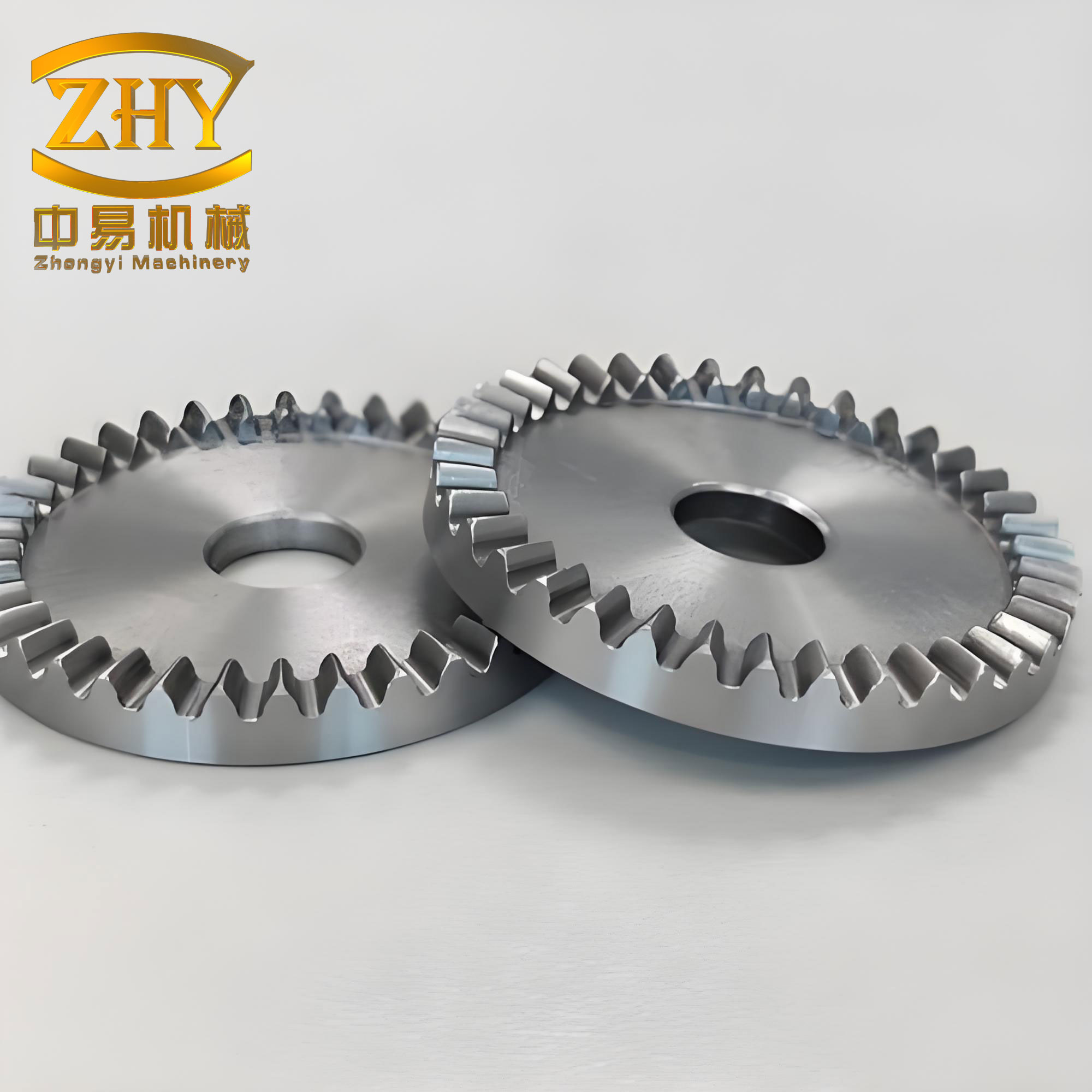
The main logic of my study is as follows. First, I generate the face gear tooth surface and calculate the meshing trajectory. Second, I design a circular-pit micro-texture layout along that trajectory. Third, I quantify the effects of the micro-texture on time-varying meshing stiffness and transmission error. Fourth, I insert these internal excitations into a six-degree-of-freedom nonlinear dynamic model of the face gear system. Fifth, I solve the equations numerically and analyze the vibration response. Finally, I perform experiments on a face gear test rig under oil-jet lubrication to examine how speed, load, and lubrication modify the micro-texture effect.
Face Gear Tooth Surface Generation and Meshing Trajectory
I derive the face gear tooth surface from the kinematic relationship between a shaper cutter and the face gear. The shaper cutter is an involute spur gear. During generation, the shaper cutter rotates about its own axis, while the face gear rotates about its own axis. The two rotations satisfy the following relation:
$$
\phi_2 = \frac{N_s}{N_2}\phi_s
$$
where \(\phi_s\) is the shaper cutter rotation angle, \(\phi_2\) is the face gear rotation angle, \(N_s\) is the number of shaper cutter teeth, and \(N_2\) is the number of face gear teeth. The shaft angle is \(90^\circ\). The involute tooth surface of the shaper cutter can be written in its local coordinate system as
$$
\mathbf{r}_s(u_s,l_s)=
\begin{bmatrix}
r_{bs}[\sin(u_0+u_s)-u_s\cos(u_0+u_s)]\\
r_{bs}[\cos(u_0+u_s)+u_s\sin(u_0+u_s)]\\
l_s\\
1
\end{bmatrix}
$$
where \(r_{bs}\) is the base circle radius of the shaper cutter, \(u_s\) is the involute roll parameter, \(l_s\) is the axial parameter, and \(u_0\) is the angular offset of the tooth space. The normal vector of the shaper cutter surface is
$$
\mathbf{n}_s=
\begin{bmatrix}
\cos(u_0+u_s)\\
-\sin(u_0+u_s)\\
0
\end{bmatrix}
$$
The coordinate transformation from the shaper cutter system to the face gear system can be expressed by a homogeneous matrix \(\mathbf{M}_{2s}\). The face gear surface is obtained by transforming the shaper cutter surface and applying the meshing condition:
$$
\mathbf{r}_2(u_s,l_s,\phi_s)=\mathbf{M}_{2s}\mathbf{r}_s(u_s,l_s)
$$
$$
f(u_s,l_s,\phi_s)=\mathbf{n}_s\cdot \mathbf{v}_s^{(s2)}=0
$$
Here \(\mathbf{v}_s^{(s2)}\) is the relative velocity between the shaper cutter and the face gear at the contact point. Solving the meshing equation together with the transformed surface yields the face gear working tooth surface and the meshing trajectory. The face gear pair used in my study has the parameters listed in Table 1.
| Parameter | Unit | Value |
|---|---|---|
| Pinion tooth number | – | 21 |
| Face gear tooth number | – | 48 |
| Shaper cutter tooth number | – | 22 |
| Module | mm | 3.9 |
| Pressure angle | deg | 25 |
| Shaft angle | deg | 90 |
I generate a point cloud of the face gear tooth surface by substituting the design parameters into the derived equations. The point cloud is then imported into a computer-aided design environment, where array and fill operations produce a solid face gear model. Because a face gear can suffer from undercutting and tip sharpening, I restrict the inner and outer radii according to face gear width design criteria. The resulting meshing trajectory is a curve that lies approximately at \(Y=94.5\) mm for the face gear pair considered here. I verify the theoretical trajectory by finite element contact analysis. The simulated contact stress region is an approximately elliptical area, and the maximum stress point lies close to the calculated meshing trajectory. This agreement confirms that the derived face gear surface and meshing trajectory are correct.
The contact stress distribution also shows that the face gear tooth surface should be textured over the entire working surface, not only near the pitch region. The micro-textures must be placed so that they intersect the meshing trajectory as much as possible. In my design, the circular pits are arranged on the working tooth surface and are projected from a sketch onto the complex face gear surface. The main design parameters are pit diameter \(D\), pit depth \(H\), pit spacing \(L\), and number of pits along the tooth height \(N\). Table 2 summarizes the design ranges that I use for the optimization study.
| Texture parameter | Symbol | Range |
|---|---|---|
| Pit diameter | \(D\) | 0.4-0.8 mm |
| Pit depth | \(H\) | 0.1-0.3 mm |
| Pit spacing | \(L\) | 0.8-1.2 mm |
| Number along tooth height | \(N\) | 3-8 |
Time-Varying Meshing Stiffness of a Micro-Textured Face Gear
Time-varying meshing stiffness is one of the most important internal excitations in a face gear transmission. Because a face gear pair makes point contact and the contact region is an ellipse, the standard stiffness formula for spur gears cannot be directly applied. I use a strain-energy method. In a quasi-static finite element analysis, the strain energy caused by bending, shear, and axial compression is calculated separately. The corresponding stiffness components are
$$
K_b=\frac{F^2}{2U_b},\qquad
K_s=\frac{F^2}{2U_s},\qquad
K_a=\frac{F^2}{2U_a}
$$
where \(F\) is the normal meshing force and \(U_b\), \(U_s\), and \(U_a\) are the bending, shear, and axial compression strain energies. Since the contact area of a heavily loaded face gear is relatively large, I neglect Hertz contact stiffness and foundation compliance in this stage. The total time-varying meshing stiffness of the face gear pair is then approximated as
$$
K_n=\frac{F^2}{2(U_a+U_b+U_s)}
$$
For a smooth face gear without micro-textures, the time-varying meshing stiffness varies in an approximately sinusoidal manner. The face gear pair can enter single-tooth, double-tooth, and even triple-tooth meshing regions. The minimum stiffness often appears when the face gear pair is in the triple-tooth meshing state. When circular-pit micro-textures are added, the average stiffness decreases by about \(15\%\). The largest changes occur near the peaks and valleys of the stiffness curve, which correspond to the beginning of meshing and the end of meshing. This behavior suggests that the micro-textures affect the stress concentration near the tooth tip and the transition between meshing states.
I perform single-factor simulations for pit diameter, pit depth, and number of pits along the tooth height. The pit spacing is not included in the single-factor study at this stage because the limited face gear width does not allow a sufficiently wide spacing range. The general trends are summarized in Table 3.
| Factor | Observed effect on time-varying meshing stiffness |
|---|---|
| Pit diameter \(D\) | Strong influence; stiffness changes with diameter, especially near peak and valley regions |
| Pit depth \(H\) | Non-monotonic; a maximum appears near \(H=0.3\) mm |
| Number of pits \(N\) | Moderate influence in single-factor tests, but weak in multi-factor response surface analysis |
| Pit spacing \(L\) | Not fully resolved in single-factor tests; later multi-factor analysis shows an optimum near \(L=1.04\) mm |
Transmission Error of a Micro-Textured Face Gear Pair
Transmission error is another key internal excitation in a face gear system. It is defined as the difference between the actual rotation angle of the driven face gear and the ideal rotation angle determined by the gear ratio. The basic transmission error is
$$
TE=\theta_g-\frac{z_p}{z_g}\theta_p
$$
where \(\theta_g\) is the driven face gear rotation angle, \(\theta_p\) is the driving pinion rotation angle, \(z_p\) is the pinion tooth number, and \(z_g\) is the face gear tooth number. Under load, the loaded transmission error is
$$
LTE(T)=\theta_g R_g-\frac{z_p}{z_g}\theta_p R_g
$$
For a face gear, there is no conventional base circle. I therefore define the effective radius as
$$
R_g=R_m\cos\alpha_n
$$
where \(R_m\) is the radius of the meshing trajectory and \(\alpha_n\) is the normal pressure angle. In my model, \(R_m=94.5\) mm. I calculate transmission error by first eliminating the initial gap caused by mesh discretization, then applying a gradual load, and finally releasing the rotational degree of freedom of the pinion. This procedure gives the theoretical loaded transmission error at different meshing positions.
When circular-pit micro-textures are introduced, the loaded transmission error of the face gear pair decreases by approximately \(13.5\%\). This result is similar to the trend reported for spur gears with bio-inspired surface textures. However, the variation of transmission error with pit diameter, depth, and number does not show a clear monotonic trend. The effect is strongest near the peaks and valleys of the transmission error curve, which again correspond to the beginning and end of meshing. For the dynamic model, I fit the obtained transmission error into a Fourier series:
$$
e_n(t)=e_m+\sum_{l=1}^{N_e} A_{el}\cos(l\Omega_h t+\Phi_{el})
$$
where \(e_m\) is the mean transmission error, \(A_{el}\) is the amplitude of the \(l\)-th harmonic, \(\Omega_h\) is the meshing angular frequency, and \(\Phi_{el}\) is the phase angle. This Fourier representation is then used as the static transmission error input in the face gear dynamic equations.
Response Surface Analysis of Texture Parameters
The interaction among texture parameters is important. A parameter that appears beneficial in a single-factor test may not remain optimal when other parameters change. I therefore use response surface methodology to study the combined effects of diameter, depth, spacing, and number on the time-varying meshing stiffness of the face gear. The first design uses a Box-Behnken sampling scheme for the variables \(D\), \(H\), and \(N\). The second design uses an optimized Latin hypercube sampling scheme for \(D\), \(H\), and \(L\).
For the \(D-H-N\) study, thirteen design points are generated. A universal Kriging model is used to fit the response. The fitted function has the form
$$
y = 31432623280.81 – 172072003.75x_1 – 15652694.67x_2 + \cdots
$$
where \(x_1\) represents \(N\), \(x_2\) represents \(D\), and \(x_3\) represents \(H\). The model accuracy is given in Table 4. The response surfaces show that the number of pits along the tooth height has a very small influence on the meshing stiffness compared with diameter and depth. The sensitivity analysis confirms that \(N\) is almost negligible. This means that when micro-textures are distributed away from the tooth root, their density can be adjusted to improve lubrication without strongly affecting the face gear meshing stiffness.
| Accuracy measure | Value | Acceptance criterion |
|---|---|---|
| \(R^2\) | 0.97918 | 0.9 |
| RMSE | 0.08984 | 0.2 |
| MAE | 0.17895 | 0.3 |
For the \(D-H-L\) study, fifty design points are generated by optimized Latin hypercube sampling. A third-order polynomial regression model is used. The response surfaces show multiple optimization directions, and the coupling effect of diameter, depth, and spacing can reach about \(102\%\) in terms of stiffness variation. The pit spacing has an optimum near \(L=1.04\) mm. At this spacing, the meshing stiffness reaches a maximum. The sensitivity analysis shows that the meshing stiffness is most sensitive to pit depth and least sensitive to pit diameter. A shallower depth and a smaller diameter reduce the weakening effect on meshing stiffness. The fitted model accuracy is shown in Table 5.
| Accuracy measure | Value | Acceptance criterion |
|---|---|---|
| \(R^2\) | 0.91214 | 0.9 |
| RMSE | 0.09294 | 0.2 |
| MAE | 0.21238 | 0.3 |
The response surface results give a clear design direction. A smaller pit diameter and a shallower pit depth are preferred if the goal is to preserve the meshing stiffness of the face gear. The pit spacing should be near the optimum value. The pit number has a weak influence on stiffness and can therefore be used as a primary parameter for improving the lubrication performance of the face gear without causing a large stiffness penalty.
Nonlinear Dynamic Model of the Face Gear Transmission
I establish a six-degree-of-freedom lumped-parameter model of the face gear transmission. The coordinates are chosen as
$$
\mathbf{q}=
\begin{bmatrix}
X_1 & Z_1 & \theta_{y1} & X_2 & Z_2 & \theta_{z2}
\end{bmatrix}^T
$$
where \(X_1\) and \(Z_1\) are the lateral displacements of the pinion, \(X_2\) and \(Z_2\) are the lateral displacements of the face gear, \(\theta_{y1}\) is the pinion rotation about its own axis, and \(\theta_{z2}\) is the face gear rotation about its own axis. The normal displacement along the meshing line is
$$
X_n=(X_1-X_2)\cos\alpha+(Z_1-Z_2)\sin\alpha+r_{b1}\theta_{y1}-r_m\theta_{z2}-e_n(t)
$$
where \(\alpha\) is the pressure angle, \(r_{b1}\) is the pinion base radius, and \(r_m\) is the effective face gear radius at the meshing point. The normal meshing force is
$$
F_n=\bar{k}(t)f(X_n)+c_m\dot{X}_n
$$
where \(\bar{k}(t)\) is the time-varying meshing stiffness, \(c_m\) is the meshing damping, and \(f(X_n)\) is the backlash function. The backlash function is
$$
f(X_n)=
\begin{cases}
X_n-b_c, & X_n>b_c\\
0, & |X_n|\le b_c\\
X_n+b_c, & X_n<-b_c
\end{cases}
$$
The time-varying meshing stiffness is represented by a Fourier series:
$$
k(t)=k_m+\sum_{l=1}^{N_k} A_{kl}\cos(l\Omega_h t+\Phi_{kl})
$$
where \(k_m\) is the mean meshing stiffness, \(A_{kl}\) is the amplitude of the \(l\)-th harmonic, and \(\Phi_{kl}\) is the phase angle. The equations of motion for the face gear system are
$$
m_1\ddot{X}_1+c_{x1}\dot{X}_1+k_{x1}X_1=F_n\cos\alpha
$$
$$
m_1\ddot{Z}_1+c_{z1}\dot{Z}_1+k_{z1}Z_1=F_n\sin\alpha
$$
$$
I_{1y}\ddot{\theta}_{y1}=T_1-F_n r_{b1}
$$
$$
m_2\ddot{X}_2+c_{x2}\dot{X}_2+k_{x2}X_2=-F_n\cos\alpha
$$
$$
m_2\ddot{Z}_2+c_{z2}\dot{Z}_2+k_{z2}Z_2=-F_n\sin\alpha
$$
$$
I_{2z}\ddot{\theta}_{z2}=-T_2+F_n r_m
$$
The equivalent mass of the face gear pair is
$$
m_e=
\frac{1}{
\frac{\cos^2\alpha}{m_1}
+\frac{\sin^2\alpha}{m_2}
+\frac{r_{b1}^2}{I_{1y}}
+\frac{r_m^2}{I_{2z}}
}
$$
The natural frequency is \(\omega_n=\sqrt{k_m/m_e}\). I nondimensionalize the equations by introducing
$$
X=b_c x,\qquad \tau=\omega_h t,\qquad \omega_h=\frac{\Omega_h}{\omega_n}
$$
After nondimensionalization, the face gear dynamic equations can be written in a compact matrix form:
$$
\ddot{\mathbf{y}}+\mathbf{A}\dot{\mathbf{y}}+\mathbf{B}\mathbf{y}+\mathbf{C}f(x_n)=\mathbf{F}_m+\mathbf{F}_e
$$
where \(\mathbf{y}\) is the state vector, \(\mathbf{A}\) contains damping terms, \(\mathbf{B}\) contains stiffness terms, \(\mathbf{C}\) contains nonlinear meshing terms, \(\mathbf{F}_m\) is the mean load vector, and \(\mathbf{F}_e\) is the excitation vector from transmission error and stiffness fluctuation. The main dimensionless parameters are listed in Table 6.
| Parameter | Value | Parameter | Value |
|---|---|---|---|
| Pinion mass \(m_1\) | 0.3 kg | Dimensionless support damping \(\zeta_{j2}\) | 0.08 |
| Face gear mass \(m_2\) | 2.613 kg | Dimensionless pinion mesh damping \(\zeta_{m1}\) | 0.7 |
| Equivalent mass \(m_e\) | 0.2 kg | Dimensionless face gear mesh damping \(\zeta_{m2}\) | 0.08 |
| Natural frequency \(\omega_n\) | 43589 rad/s | Dimensionless meshing damping \(\zeta_m\) | 1.04 |
| Dimensionless excitation frequency \(\omega_h\) | 0.003 | Dimensionless pinion support stiffness \(\kappa_{j1}\) | 0.175 |
| Support stiffness \(k_{ji}\) | \(1\times10^8\) N/m | Dimensionless face gear support stiffness \(\kappa_{j2}\) | 0.02 |
| Support damping \(c_{sji}\) | \(3\times10^6\) N s/m | Dimensionless pinion mesh stiffness \(\kappa_{m1}\) | \(0.67\kappa(\tau)\) |
| Meshing damping \(c_m\) | 18216 N s/m | Dimensionless face gear mesh stiffness \(\kappa_{m2}\) | \(0.08\kappa(\tau)\) |
I solve the nonlinear equations using a fourth-to-fifth order variable-step Runge-Kutta method. The initial conditions are zero. The numerical solution provides time-domain waveforms, phase portraits, Poincare maps, and fast Fourier transform spectra. These tools allow me to identify period-one motion, multi-period motion, and possible transitions to more complex dynamic states.
Dynamic Response Without Micro-Textures
For a smooth face gear without micro-textures, the relative displacement at the meshing point shows stable periodic vibration. The phase portrait is a closed ellipse, indicating periodic motion. The Poincare map contains a single isolated point, which confirms period-one motion. The frequency spectrum is dominated by the main meshing frequency, and there are no strong subharmonic or superharmonic components. These features indicate that the smooth face gear system operates in a stable, weakly nonlinear periodic state under the selected conditions.
Effect of Pit Diameter on Face Gear Vibration
When micro-textures are introduced, the average amplitude of the relative displacement at the meshing point decreases by approximately \(80\%\). This is a very strong reduction in vibration amplitude. However, changing the pit diameter has only a limited effect on the dynamic response. In the time domain, the change in average vibration amplitude is less than \(5\%\). In the phase portrait, a larger diameter tends to make the trajectory more compact, which suggests a slight reduction in vibration energy. Table 7 shows the Poincare points for different pit diameters. The dimensionless displacement first increases and then decreases with diameter, while the dimensionless velocity remains zero. The system remains in period-one motion. Therefore, pit diameter can be selected mainly for lubrication performance, because its influence on the face gear vibration state is relatively weak.
| Pit diameter (\(\mu\)m) | Dimensionless displacement \(x_n\) | Dimensionless velocity \(\dot{x}_n\) |
|---|---|---|
| 200 | 0.0034 | 0 |
| 400 | 0.0040 | 0 |
| 600 | 0.0048 | 0 |
| 800 | 0.0039 | 0 |
Effect of Pit Depth on Face Gear Vibration
Pit depth has a much clearer influence on the face gear dynamic response. As the pit depth increases, the time-domain amplitude of the relative displacement decreases. The phase trajectory becomes more compact, which indicates that the vibration energy is reduced and the motion becomes more stable. Deeper pits can reduce the contact impact on the face gear tooth surface and therefore suppress vibration. The Poincare map shows that the discrete points move toward the origin and become more concentrated as depth increases. At a depth of \(300\ \mu\text{m}\), however, the Poincare map shows two discrete points. This indicates that the system changes from period-one motion to a more complex motion state. I interpret this depth as a critical value for the dynamic stability of the micro-textured face gear system. Increasing the depth beyond this value may not always be beneficial, because it can trigger a qualitative change in the nonlinear dynamic behavior.
Effect of Pit Number on Face Gear Vibration
The number of pits along the tooth height also affects the dynamic response. As the number of pits increases, the amplitude of the relative displacement decreases. The phase trajectory becomes more compact. In the Poincare map, the dimensionless displacement increases with the number of pits, but the change becomes small when the number increases from five to six. The dimensionless velocity remains zero, so the system stays in a simple periodic state. Table 8 summarizes the Poincare results. The number of pits is therefore a useful parameter for reducing vibration amplitude, but its effect on the qualitative motion state is limited under the conditions studied.
| Number of pits | Dimensionless displacement \(x_n\) | Dimensionless velocity \(\dot{x}_n\) |
|---|---|---|
| 3 | 0.0017 | 0 |
| 4 | 0.0020 | 0 |
| 5 | 0.0034 | 0 |
| 6 | 0.0036 | 0 |
Experimental Study of Micro-Textured Face Gear Dynamics
I also perform experiments on a face gear transmission test rig to examine the micro-texture effect under oil-jet lubrication. The test rig consists of a mechanical frame, a servo control system, a displacement control system, and a lubrication control system. Torque and speed sensors are installed on the input and output shafts. The input side is connected to a pinion, and the output side is connected to the face gear. The main specifications are listed in Table 9. The lubrication condition is oil-jet lubrication with a flow rate of \(1.22\ \text{L/min}\) and an oil temperature of \(30^\circ\text{C}\).
| Item | Input side: pinion | Output side: face gear |
|---|---|---|
| Speed range | 0-1500 rpm | 0-1250 rpm |
| Torque range | 0-400 N m | 0-2000 N m |
| Applicable size | 80-270 mm | 200-400 mm |
| Transmission ratio | 1.2-5 | |
During assembly, I control the center distance between the pinion and the face gear according to the shaper cutter relation. The center distance offset is
$$
\Delta=\frac{\Delta N m}{2}
$$
where \(\Delta N\) is the tooth number difference between the shaper cutter and the pinion, and \(m\) is the module. I check the face gear runout with a dial indicator and ensure that the shaft angle is \(90^\circ\). A red-lead contact test is used to verify the meshing position. The contact pattern on the face gear tooth surface is close to the elliptical region predicted by finite element analysis. This confirms that the face gear is correctly installed. Because a low-hardness face gear material can undergo plastic deformation under impact loads, I use conservative load levels in the experiments.
The micro-textures are fabricated by laser processing. The design parameters are a diameter of \(500\ \mu\text{m}\), a depth of \(50\ \mu\text{m}\), and a spacing of \(1.2\ \text{mm}\) along the tooth height. The textures are placed on the loaded tooth surface. Vibration sensors are mounted on the input and output shafts in the \(x\), \(y\), and \(z\) directions. The sampling frequency is \(25000\ \text{Hz}\), and the measurement range is \(50g\).
Startup Vibration Response
For a smooth face gear pair without micro-textures, the startup oscillation lasts about \(1\ \text{s}\). The \(z\)-direction oscillation is less obvious than the \(x\)- and \(y\)-direction oscillations. At \(50\ \text{rpm}\), the difference between the startup oscillation amplitude and the steady-state amplitude is not large, because the servo motor is less stable at low speed. At higher speeds, the startup oscillation is clearer. When micro-textures are added, the output shaft vibration changes from a stable periodic form to a more fluctuating form. The reason is that the micro-textures disturb the original elliptical contact stress distribution and create local stress concentrations at pit edges. As a result, low-frequency components become more complex in the frequency spectrum. The micro-textured face gear system is more likely to resonate at low speed.
At the same time, the micro-textured face gear pair shows a weaker startup oscillation. The startup oscillation amplitude is reduced by about \(25\%\) to \(50\%\). In the steady-state stage, the micro-texture reduces the amplitude by about \(50\%\), especially at higher speeds. At speeds below \(100\ \text{rpm}\), the effect is not obvious. I attribute this to two competing mechanisms. First, the micro-textures improve the hydrodynamic lubrication of the face gear pair and reduce vibration. Second, the micro-textures introduce additional low-frequency excitation and can cause local resonance at low speed. The two effects partially cancel each other.
The frequency spectra also show lower overall amplitudes for the micro-textured face gear system. This means that the vibration energy is distributed more evenly, and high-frequency components are suppressed. The system becomes more stable and recovers more quickly from internal or external disturbances. This is beneficial for reducing vibration and noise in a face gear transmission.
Load-Dependent Vibration Response
I compare the output shaft vibration under \(10\ \text{N m}\) and \(50\ \text{N m}\) at \(100\ \text{rpm}\). Under \(10\ \text{N m}\), the vibration amplitude is relatively small, and the \(x\)- and \(z\)-direction responses are stable. Under \(50\ \text{N m}\), the vibration amplitude increases significantly. The \(x\)-direction response becomes the most prominent. The waveform becomes denser and more complex, which indicates stronger nonlinearity and more concentrated vibration energy release. The frequency spectrum under \(10\ \text{N m}\) has clear low-frequency peaks that decay quickly. Under \(50\ \text{N m}\), the spectrum becomes more complex, and several frequency components increase in amplitude. The micro-texture effect is therefore much stronger under high load than under low load. In a face gear transmission, high load increases the contact stiffness and the meshing impact, which amplifies the influence of surface texture on the dynamic response.
Transmission Error Experiments Under Lubrication
I also measure the face gear transmission error under different speeds and loads. During startup, the face gear pair experiences a large transmission error fluctuation. This fluctuation increases with speed. After the micro-textures are added, the transmission error increases by about \(40\%\). The fluctuation becomes more severe because the micro-textures change the local contact and lubrication state. As speed increases, the relative sliding velocity on the meshing tooth surface increases, which reduces the transmission error fluctuation caused by the micro-textures. However, the mean transmission error does not change much with speed.
Under load, the behavior is strongly influenced by lubrication. For a smooth face gear pair, the transmission error first decreases and then increases as load increases. For a micro-textured face gear pair under oil-jet lubrication, the transmission error increases with load. This is opposite to the dry-friction simulation result, where the micro-texture reduced the transmission error. The reason is that the micro-texture changes the lubricant distribution, film thickness, and contact pressure. Under full lubrication, the micro-texture can increase the transmission error rather than reduce it. This finding shows that the micro-texture effect on a face gear pair is highly dependent on the lubrication condition.
Summary of Findings
My study shows that tooth surface micro-textures have a non-asymmetric and condition-dependent influence on face gear dynamics. The main findings can be summarized as follows. The circular-pit micro-texture reduces the time-varying meshing stiffness of the face gear by about \(15\%\). The transmission error under dry contact is reduced by about \(13.5\%\), but the variation with texture parameters is not monotonic. The response surface analysis shows that pit diameter and depth are the most important parameters for meshing stiffness, while pit number has a weak effect. Pit spacing has an optimum value near \(1.04\ \text{mm}\). In the nonlinear dynamic model, the micro-texture reduces the average vibration amplitude of the face gear meshing point by about \(80\%\), while the system remains in period-one motion. Pit diameter and pit number have limited influence on the qualitative motion state. Pit depth is the key parameter that can trigger a transition from period-one motion to a more complex state at about \(300\ \mu\text{m}\).
The experiments under oil-jet lubrication reveal that the micro-texture effect is strongly modified by speed and load. At low speed, the micro-texture does not significantly suppress vibration and can induce low-frequency resonance. At high load, the micro-texture increases the vibration spectrum amplitude. Under full lubrication, the transmission error behavior is completely different from the dry-contact simulation. The micro-texture increases the mean transmission error and its fluctuation. Therefore, a face gear with micro-textures can achieve better transmission performance in the high-speed and low-load region, but the design must account for the lubrication condition and the operating load. The results provide a foundation for optimizing micro-textured face gear surfaces with both tribological and dynamic requirements in mind.
Design Implications and Outlook
For a face gear transmission, the micro-texture design should not be based only on friction reduction. The dynamic consequences must be considered. If the goal is to preserve meshing stiffness, a small pit diameter and a shallow pit depth are preferable. If the goal is to reduce vibration, a moderate number of pits can be used because the pit number has a weak effect on stiffness. If the goal is to improve lubrication, the pit spacing can be tuned near the optimum value, but the depth should be kept below the critical value that triggers complex motion. In future work, a fluid-solid coupling simulation of the lubricated face gear contact would provide more accurate dynamic excitation inputs. Face gear tooth modification should also be studied because the meshing trajectory can shift toward the inner radius under load, causing stress concentration. Improving the manufacturing accuracy of the face gear and the micro-texture will reduce measurement noise and make the dynamic effect of the texture clearer. These steps will support the reliable design of high-performance face gear transmissions.