
The pursuit of high-performance power transmission systems is a constant endeavor in mechanical engineering. Among the various solutions, screw gear drives, particularly worm drives, hold a significant position due to their unique ability to provide high reduction ratios, compact design, and self-locking characteristics in a single stage. They are indispensable in applications ranging from precision instruments and robotics to heavy-duty machinery in aerospace and defense. However, conventional worm drives often face limitations in achieving multi-load output from a single input shaft or in further optimizing their load distribution and contact characteristics.
To address these needs, a novel configuration known as the Plane Enveloping Internal Meshing Screw Gear drive has been proposed. This innovative design fundamentally rethinks the worm-wheel relationship. Unlike traditional external meshing worm gears, this system utilizes an internal gear as the driven member, enveloped by a worm whose thread surface is generated by a plane. This architecture inherently allows a single worm to drive multiple internal wheels arranged around it, enabling compact multi-output systems. Furthermore, by inheriting the meshing principle of plane-enveloping toroidal worm gears, it promises superior load-carrying capacity and favorable contact conditions. The core element defining the geometry of this internal meshing screw gear is the orientation of its generating plane, characterized by the generating plane inclination angle. This parameter critically influences the tooth form, contact path, and ultimately, the meshing performance of the entire drive system.
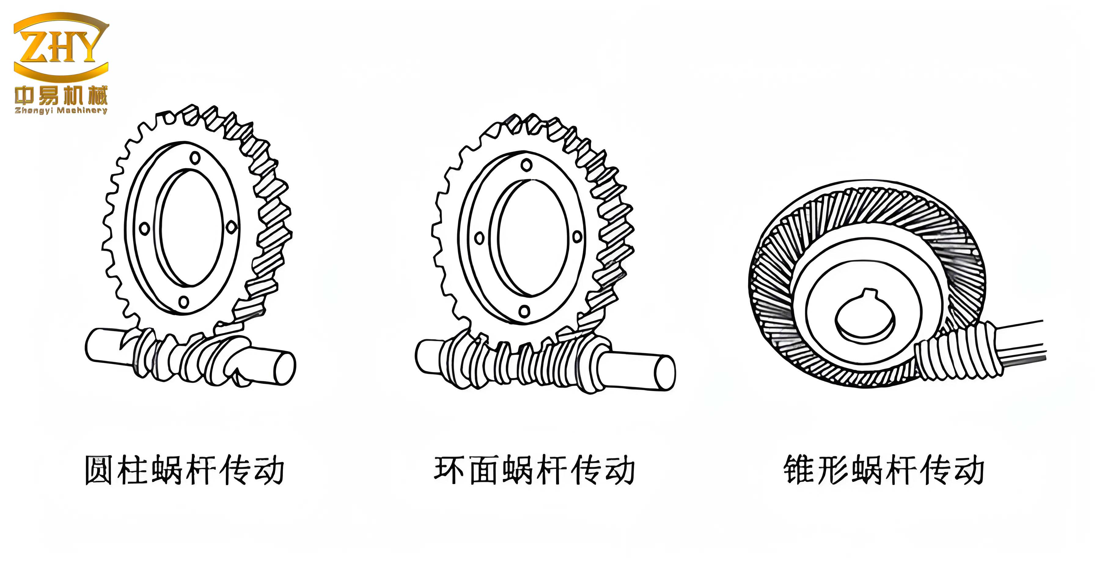
In this analysis, I will investigate the influence of the generating plane inclination angle on the meshing performance of the plane enveloping internal meshing screw gear drive. The primary metric for evaluating meshing performance will be the induced normal curvature at the contact point, as it is directly related to the contact stress and surface durability. The investigation is conducted by establishing the mathematical model of the gear set based on gear meshing theory, followed by a comprehensive numerical analysis to map the relationship between the inclination angle and the performance metric under varying operational parameters.
1. Mathematical Foundation of the Internal Meshing Screw Gear
1.1 Coordinate System Establishment
To derive the meshing conditions and tooth surface equations, a set of coordinate systems is established. The fixed coordinate systems \( S_1 (O_1 – x_1, y_1, z_1) \) and \( S_2 (O_2 – x_2, y_2, z_2) \) are attached to the frame for the screw gear (worm) and the internal gear (wheel), respectively. The moving coordinate systems \( S_1′ (O_1′ – x_1′, y_1′, z_1′) \) and \( S_2′ (O_2′ – x_2′, y_2′, z_2′) \) are rigidly connected to the screw gear and the internal gear, rotating with angular velocities \( \omega_1′ \) and \( \omega_2′ \) about their respective axes.
The generating plane \(\Sigma\) is defined in a moving coordinate system \( S_0 (O_0 – x_0, y_0, z_0) \). The \( y_0 \) and \( z_0 \) axes lie on this plane, with the origin \( O_0 \) located on the base circle of the internal gear. A point \( p \) on the generating plane is defined by coordinates \( (0, u, v) \) in \( S_0 \), where \( u \) and \( v \) are parameters. The vector from \( O_2′ \) to \( O_0 \) is \( \mathbf{r}_0 = (0, r, 0) \), where \( r \) is the base circle radius. The relative positions of the screw gear and internal gear are defined by the center distance \( A \) and the installation angle (wheel inclination angle) \( \delta_F \). The generating plane itself is inclined by the key parameter under study: the generating plane inclination angle \( \beta \).
The transformation from the internal gear coordinate system \( S_2′ \) to the screw gear coordinate system \( S_1′ \) is given by the homogeneous transformation matrix \( \mathbf{M}_{2’1′} \):
$$
\mathbf{M}_{2’1′} = \begin{bmatrix}
p_1 + l_2 p_2 & l_2 p_4 – p_3 & -l_1 g_2 & A g_1 \\
l_2 p_3 – p_4 & p_2 + l_2 p_1 & -l_1 g_1 & -A g_2 \\
l_1 h_2 & l_1 h_1 & l_2 & 0 \\
0 & 0 & 0 & 1
\end{bmatrix}
$$
where \( g_1 = \cos \phi_1, g_2 = \sin \phi_1, h_1 = \cos \phi_2, h_2 = \sin \phi_2, l_1 = \cos \delta_F, l_2 = \sin \delta_F, p_1 = g_1 h_1, p_2 = g_2 h_2, p_3 = g_1 h_2, p_4 = g_2 h_1 \). Here, \( \phi_1 \) and \( \phi_2 \) are the rotational angles of the screw gear and internal gear, respectively.
The transformation from the generating plane coordinate system \( S_0 \) to the internal gear system \( S_2′ \) is:
$$
\mathbf{M}_{02′} = \begin{bmatrix}
0 & 1 & 0 & 0 \\
-\cos \beta & 0 & -\sin \beta & r \\
-\sin \beta & 0 & \cos \beta & 0 \\
0 & 0 & 0 & 1
\end{bmatrix}
$$
1.2 Meshing Equation
The fundamental condition for conjugate meshing between the screw gear and the internal gear is that the common surface normal vector at the contact point is perpendicular to the relative velocity vector of the two surfaces at that point. This condition is expressed by the meshing equation:
$$
\Phi = \mathbf{v}^{(12)} \cdot \mathbf{n}_0 = 0
$$
where \( \mathbf{v}^{(12)} \) is the relative velocity vector expressed in the \( S_0 \) system and \( \mathbf{n}_0 \) is the unit normal vector to the generating plane (which is constant in \( S_0 \), e.g., \( \mathbf{n}_0 = (1, 0, 0) \)).
Solving the meshing equation yields a relationship between the surface parameters \( u \), \( v \), and the motion parameter \( \phi_2 \):
$$
v = \frac{B_1}{B_2}
$$
where
$$
\begin{aligned}
B_1 &= u \cos \beta \sin \delta_F + A \cos \beta \cos \phi_2 \sin \delta_F – u \cos \phi_2 \cos \delta_F \sin \beta \\
& \quad – i_c u \cos \beta + r \cos \delta_F \sin \beta \sin \phi_2 – A \cos \delta_F \sin \beta \\
B_2 &= \cos \delta_F \sin \phi_2 \quad (\phi_2 \neq 0)
\end{aligned}
$$
and \( i_c = z_1 / z_2 \) is the gear ratio, with \( z_1 \) and \( z_2 \) being the number of threads on the screw gear and teeth on the internal gear, respectively.
1.3 Tooth Surface Equations
The tooth surface of the internal meshing screw gear is the locus of all contact points traced during the enveloping process. The equations for the screw gear surface \( \mathbf{r}^{(1)}(u, \phi) \) and the internal gear surface \( \mathbf{r}^{(2)}(u, \phi) \) are obtained by coordinate transformations:
$$
\begin{aligned}
\mathbf{r}^{(1)}(u, \phi) &= \mathbf{M}_{2’1′} \cdot \mathbf{M}_{02′} \cdot [0, u, v(u, \phi), 1]^T \\
\mathbf{r}^{(2)}(u, \phi) &= \mathbf{M}_{02′} \cdot [0, u, v(u, \phi), 1]^T
\end{aligned}
$$
where \( \phi = \phi_1 \) and \( \phi_2 = i_c \phi \). For a given line of contact corresponding to a constant parameter \( u = c \), these equations generate the three-dimensional surfaces of the mating gears. The unique geometry of this screw gear allows it to mesh with multiple internal gears positioned around its circumference.
1.4 Induced Normal Curvature
A critical parameter for assessing the contact fatigue strength and wear resistance of gear teeth is the induced normal curvature \( k^{(12)} \) along the direction of relative motion. A lower induced curvature generally leads to lower contact stress and better lubrication conditions. Based on differential geometry and gear meshing theory, the induced normal curvature can be calculated from:
$$
k^{(12)} = \frac{ (\boldsymbol{\omega}^{(12)} \times \mathbf{n}_0 – \mathbf{v}^{(12)} \cdot \frac{d\mathbf{n}_0}{ds} )^{(2)} }{\Psi}
$$
where \( \boldsymbol{\omega}^{(12)} \) is the relative angular velocity vector, \( s \) is the arc length along the contact line, and \( \Psi \) is a first-order function derived from the meshing function \( \Phi \):
$$
\Psi = \frac{d\Phi}{dt} + (\boldsymbol{\omega}^{(12)}, \mathbf{n}_0, \mathbf{v}^{(12)})
$$
The components of the relative angular velocity in \( S_0 \) are:
$$
\begin{aligned}
x_{\omega 0} &= \sin \beta (i_c – \sin \delta_F) – \cos \beta \cos \delta_F \cos \phi_2 \\
y_{\omega 0} &= \cos \delta_F \sin \phi_2 \\
z_{\omega 0} &= -\cos \beta (i_c – \sin \delta_F) – \cos \delta_F \cos \phi_2 \sin \beta
\end{aligned}
$$
2. Influence of Generating Plane Inclination Angle on Meshing Performance
2.1 Selection of Critical Analysis Location
To understand the influence of the generating plane inclination angle \( \beta \), it is essential to first identify the most critically loaded region on the gear tooth. An analysis of the induced normal curvature variation along a single contact line reveals a significant trend. Using a baseline set of parameters (Center distance \( A = 80 \) mm, \( z_1 = 1 \), \( z_2 = 40 \), \( \delta_F = 35^\circ \), base radius \( r = 23 \) mm, internal gear tip diameter \( d_a = 67 \) mm, root diameter \( d_f = 62 \) mm), the parameter \( u \) varies from the root (\( u_{min} = \sqrt{(d_f/2)^2 – r^2} \approx 57.6 \) mm) to the tip (\( u_{max} = \sqrt{(d_a/2)^2 – r^2} \approx 63 \) mm).
The calculation of induced curvature along this contact line shows a linear decrease from the tooth root to the tip for the internal gear. This implies that the maximum induced curvature, and consequently the highest contact stress according to the Hertzian model, occurs at the root of the internal gear tooth (conversely, at the tip of the screw gear thread). This stress concentration at the root is a common challenge in gear design. Therefore, to conservatively assess the impact of \( \beta \), the analysis focuses on the condition at the tooth root (\( u = u_{min} \)).
2.2 Effect of Internal Gear Tooth Number with Varying \( \beta \)
I first investigate how the optimal range for \( \beta \) is affected by changing the number of teeth on the internal gear, \( z_2 \), while keeping the screw gear single-threaded (\( z_1 = 1 \)). Other parameters remain fixed: \( A = 80 \) mm, \( \delta_F = 35^\circ \), \( r = 23 \) mm, \( u = 57.6 \) mm. The generating plane inclination angle \( \beta \) is varied from \( 0^\circ \) to \( 90^\circ \), and the induced normal curvature is calculated for different rotation angles \( \phi_2 \) and different gear ratios \( i_c = 1/z_2 \).
The results indicate a consistent pattern: for smaller rotation angles, the induced curvature is favorable for \( \beta \) roughly between \( 0^\circ \) and \( 36^\circ \). As the rotation angle increases, the range that yields the minimum induced curvature becomes more distinct and stabilizes between approximately \( 18^\circ \) and \( 36^\circ \). This suggests that within this angular range, the internal meshing screw gear drive operates with lower contact stress potential. The trend is observable across different internal gear tooth counts, as summarized conceptually in the table below, which shows the relative magnitude of induced curvature (H: High, M: Medium, L: Low) for different \( \beta \) ranges.
| \( \beta \) Range | \( z_2 = 30 \) | \( z_2 = 40 \) | \( z_2 = 50 \) | Overall Trend |
|---|---|---|---|---|
| \( 0^\circ – 18^\circ \) | M to H | M to H | M | Generally higher curvature |
| \( 18^\circ – 36^\circ \) | L | L | L | Minimum, stable low curvature |
| \( 36^\circ – 90^\circ \) | H | H | H to M | Sharply increasing to high curvature |
A more detailed analysis focusing on the \( 18^\circ \) to \( 36^\circ \) range confirms that the induced normal curvature values are not only low but also exhibit less variation during the meshing cycle compared to angles outside this range. This stability is crucial for predictable and uniform wear in the screw gear pair.
2.3 Effect of Center Distance with Varying \( \beta \)
To generalize the finding, the analysis is repeated with the center distance \( A \) as the variable. The internal gear tooth number is fixed at \( z_2 = 40 \), and other parameters remain as before. The center distance is varied, and the induced curvature is computed for the full spectrum of \( \beta \).
The results robustly corroborate the earlier observation. Regardless of the specific center distance, the induced curvature consistently reaches its most favorable (lowest) values when \( \beta \) is within the \( 18^\circ \) to \( 36^\circ \) band. Outside this band, particularly for \( \beta > 36^\circ \), the induced curvature increases significantly, implying a drastic rise in contact stress. The following equation conceptually represents the observed relationship, where \( k^{(12)}_{max} \) is the peak induced curvature during meshing and \( f(\beta) \) is a function with a distinct minimum in the \( 18^\circ-36^\circ \) interval:
$$
k^{(12)}_{max} \approx f(\beta, A, z_2) \quad \text{with} \quad \min(f) \text{ for } \beta \in [18^\circ, 36^\circ]
$$
The table below illustrates this robustness by showing how the optimal \( \beta \) range remains effective for different center distances.
| Center Distance \( A \) (mm) | Induced Curvature at \( \beta = 15^\circ \) | Induced Curvature at \( \beta = 27^\circ \) | Induced Curvature at \( \beta = 45^\circ \) | Optimal \( \beta \) Range Confirmed? |
|---|---|---|---|---|
| 70 | High | Very Low | Very High | Yes (18°-36°) |
| 80 | Medium-High | Very Low | Very High | Yes (18°-36°) |
| 90 | Medium | Low | High | Yes (18°-36°) |
3. Discussion and Implications for Screw Gear Design
The numerical investigation leads to two primary conclusions regarding the design of plane enveloping internal meshing screw gear drives. First, the contact stress distribution across the tooth face is inherently non-uniform, with the root region of the internal gear (and the tip region of the screw gear thread) being the most critically stressed. This is a direct consequence of the linear increase in induced normal curvature towards the tooth root, a characteristic shared with other plane-enveloping worm gear types.
Second, and more importantly, the generating plane inclination angle \( \beta \) is a dominant design parameter with a clearly identifiable optimal range. The analysis demonstrates that setting \( \beta \) between \( 18^\circ \) and \( 36^\circ \) consistently minimizes the induced normal curvature at the critical contact point, irrespective of reasonable variations in the internal gear tooth count (\( z_2 \)) or the center distance (\( A \)). This finding provides a powerful and simplified guideline for the initial design phase of this novel screw gear system. Designers can select a \( \beta \) value within this range—for instance, \( 27^\circ \) as a midpoint—with confidence that it will yield favorable contact conditions, leading to higher potential load capacity and improved durability of the gear set.
This optimal range balances the geometric constraints of the internal meshing arrangement and the kinematics of the plane-enveloping process. Angles below \( 18^\circ \) may lead to insufficient tooth depth or unfavorable pressure angles, while angles above \( 36^\circ \) likely cause excessive sliding and sharper curvature on the screw gear thread surface, both scenarios resulting in higher contact stresses. The discovery of this specific effective range for the screw gear’s generating plane angle resolves a key uncertainty in its parametric design, establishing a solid theoretical foundation. It streamlines the design process by reducing the parameter space that requires extensive optimization and facilitates the rapid development of viable prototypes for this promising multi-output screw gear transmission technology.