
The process of gear shaving is a widely employed finishing operation renowned for its high productivity and cost-effectiveness. However, a persistent challenge associated with this process is the induction of a characteristic tooth profile concave error, often manifesting near the pitch circle, which detrimentally impacts the final gear’s meshing performance and noise characteristics. While significant research has focused on internal excitations like contact ratio and tool structural modifications, a fundamental investigation from the perspective of cutting mechanics, particularly the role of cutting parameters on the dynamic cutting forces, remains crucial for a holistic understanding and mitigation of this error. This article delves into the intricate relationship between key gear shaving parameters—spindle speed, radial feed, and axial feed—and the resultant cutting forces, subsequently elucidating their direct contribution to the formation mechanism of the profile error.
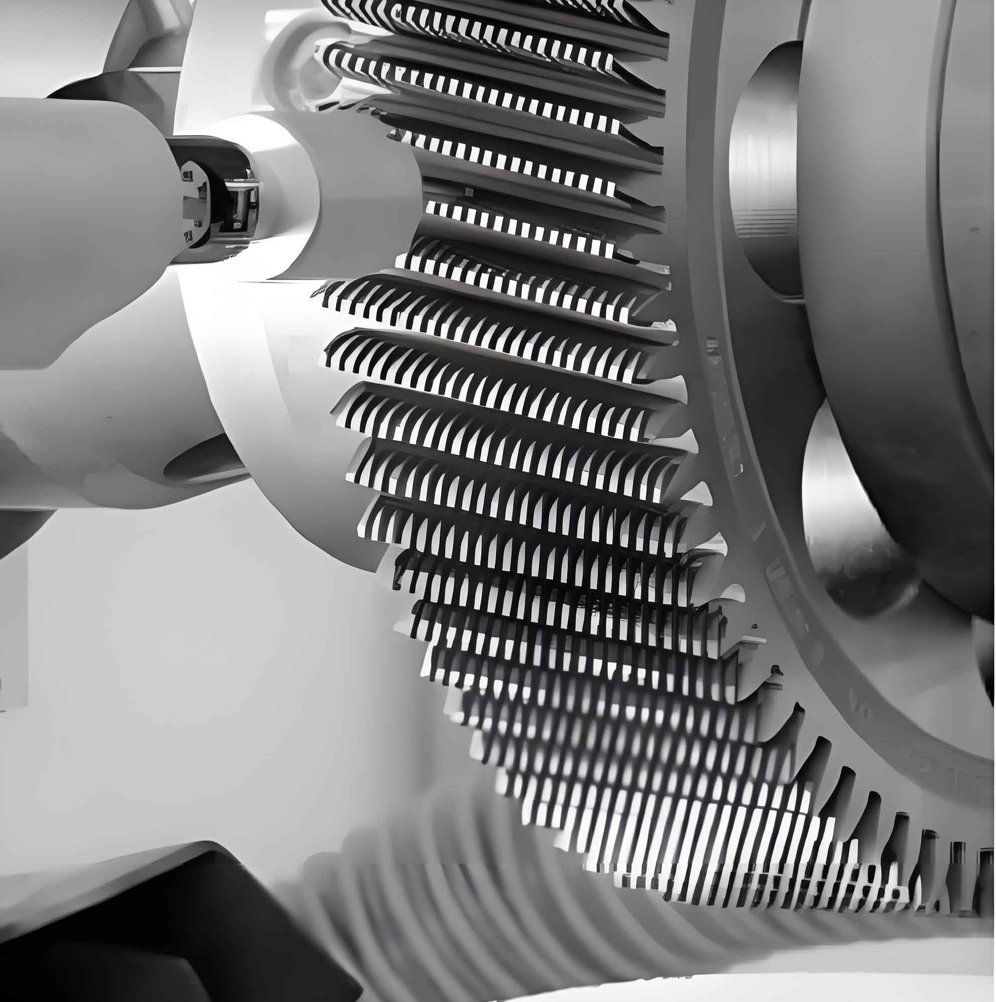
The gear shaving process is fundamentally characterized by the crossed-axes meshing of the shaving cutter and the workpiece gear. As illustrated, this setup generates a point contact between the tooth flanks. The primary cutting action does not stem from a traditional defined rake and clearance angle in the conventional sense but from the relative sliding motion between the meshing teeth, which is instigated and controlled by the machining parameters. The combination of the rotary motion of the cutter, its intermittent radial infeed, and the axial traverse of the workpiece gear along its axis facilitates the removal of a thin layer of material across the entire tooth flank. The complex, multi-point contact conditions that vary along the path of contact are central to the non-uniform force distribution and subsequent error generation in gear shaving.
To quantitatively analyze this, we establish a theoretical model for the shaving cutting force (Fc). The foundation lies in the fundamental metal cutting force theory, which can be expressed in a generalized form as:
$$ F = \tau_s A_c (1.4\xi + C) $$
where $\tau_s$ is the material’s shear yield strength, $\xi$ is the chip deformation coefficient, $C$ is a constant related to the tool’s effective rake angle, and $A_c$ is the cross-sectional area of the undeformed chip. In the context of gear shaving, the cutting area for a given tooth engagement can be related to the depth of cut and the feed. However, the instantaneous depth of cut, or more accurately the “press-cut” amount, is not explicit but is governed by the radial feed motion and the local elastic contact deformation between the meshing teeth.
The relationship between the radial feed per stroke ($f_r$) and the total material allowance ($\Delta$) to be removed is given by:
$$ f_r = \frac{\Delta}{2 \sin \alpha_n} $$
where $\alpha_n$ is the normal pressure angle. Due to the multi-tooth contact in gear shaving (with a contact ratio >1), the load is distributed among several tooth pairs. The local elastic deformation ($\delta_c$) at a specific contact point, which effectively contributes to the cutting depth, can be modeled using Hertzian contact theory for line contact, adapted for the gear geometry:
$$ \delta_c = \eta \left( \frac{3\pi \lambda F_{nc}}{2 \sum_{i=1}^{m} \frac{\kappa_i}{C_i^{3/2}} } \right)^{2/3} $$
with
$$ \lambda = \frac{1-\mu_1^2}{\pi E_1} + \frac{1-\mu_2^2}{\pi E_2} $$
Here, $\eta$ is a factor accounting for the shaving cutter’s chip pocket spacing, $F_{nc}$ is the normal force at the contact point c, $\mu_j$ and $E_j$ are Poisson’s ratio and Young’s modulus for the cutter (j=1) and workpiece (j=2), $\kappa_i$ is the difference in normal curvatures, and $C_i$ is a coefficient dependent on the principal curvatures of the contacting surfaces. Therefore, the effective instantaneous depth of cut ($a_p$) becomes a sum of the nominal material removal per feed and this elastic indentation:
$$ a_p = \Delta_{f_r} + \delta_c $$
where $\Delta_{f_r}$ is the nominal material removal corresponding to the radial feed increment.
Substituting into the basic force equation, and considering the feed per revolution, the cutting force for a specific engagement point during gear shaving can be modeled as:
$$ F_c = \tau_s f (1.4\xi + C) \left[ \frac{2 i \sin(\alpha_n) f_r}{N} + \eta \left( \frac{3\pi \lambda F_{nc}}{2 \sum \frac{\kappa_i}{C_i^{3/2}} } \right)^{2/3} \right] $$
where $f$ is the axial feed rate (mm/min), $i$ is the gear ratio, and $N$ is the spindle speed (rpm). A critical component for solving this equation is the distribution of the normal contact force $F_{nc}$ along the path of contact. This distribution is inherently linked to the total radial shaving force ($F_r$). Empirical studies have established a relationship for $F_r$ based on cutting parameters:
$$ F_r = P e^{-Q / S} $$
with
$$ P = 1385.499 N^{-0.0654} f^{0.1544} f_r^{0.5492} $$
$$ Q = 1.5096 N^{-0.055} f^{-0.0291} f_r^{-0.056} $$
where $S$ is the radial feed sequence number. Using the calculated $F_r$, the individual normal forces $F_{nc}$ at different contact points can be resolved through static equilibrium and compatibility conditions of the multi-tooth meshing system in gear shaving.
Quantitative Influence of Cutting Parameters on Shaving Forces
Employing the derived model under the principle of a single variable, we can systematically analyze the impact of each primary gear shaving parameter. The following analysis is based on a representative gear set with parameters outlined in the table below.
| Parameter | Shaving Cutter | Workpiece Gear |
|---|---|---|
| Module | 5.35 mm | 5.35 mm |
| Number of Teeth | 43 | 12 |
| Helix Angle | 11° | 11° |
| Normal Pressure Angle | 20° | 20° |
1. Effect of Spindle Speed (N)
Holding the axial feed (f = 60 mm/min) and radial feed (f_r = 0.045 mm) constant, the variation of cutting force $F_c$ along the tooth profile (from root to tip) for different spindle speeds was calculated. A key observation is the step-like variation in $F_c$, corresponding directly to the changing number of tooth pairs in contact (e.g., 4-point, 3-point, or 2-point contact zones) during the gear shaving process. The normal force $F_{nc}$, and consequently $F_c$, redistributes significantly at these transition points.
Regardless of the spindle speed, the force profile consistently shows a pronounced local maximum in the region adjacent to the pitch circle. This region often corresponds to zones of 2-point and 3-point contact where the load per tooth is highest due to the meshing kinematics. Crucially, the magnitude of $F_c$ in this critical pitch region exhibits a clear decreasing trend with increasing spindle speed, as summarized below:
| Spindle Speed, N (rpm) | Cutting Force at ~Pitch Circle, F_c (N) | Trend |
|---|---|---|
| 140 | 34.8 | Decreasing with diminishing returns |
| 170 | 30.3 | |
| 200 | 27.6 | |
| 230 | 26.5 |
This inverse relationship can be attributed to increased cutting speed reducing the specific cutting energy. Higher speeds may lead to a larger shear angle, reduced friction at the sliding interface, and thermal softening effects, all contributing to a lower force required for material deformation and removal during gear shaving. However, an excessively high speed risks inducing excessive heat, potentially compromising surface integrity.
2. Effect of Axial Feed Rate (f)
With constant spindle speed (N=170 rpm) and radial feed (f_r=0.045 mm), increasing the axial feed rate directly increases the volume of material removed per unit time. The model predicts a proportional increase in the cutting force $F_c$ across the entire tooth profile, though the characteristic step-wise pattern remains unchanged. The pitch circle region continues to experience the highest force magnitude. The quantitative effect on the force at the pitch circle is clear:
| Axial Feed, f (mm/min) | Cutting Force at ~Pitch Circle, F_c (N) | Trend |
|---|---|---|
| 30 | 14.5 | Linear Increase |
| 36 | 18.6 | |
| 51 | 24.1 | |
| 60 | 30.3 |
The relationship can be approximated as $F_c \propto f$, stemming from the direct term $f$ in the force equation. A higher $f$ increases the cross-sectional area of the material being sheared, leading to greater plastic deformation resistance and higher forces in the gear shaving contact zone.
3. Effect of Radial Feed (f_r)
The radial feed is arguably the most influential parameter in gear shaving. Maintaining N=170 rpm and f=60 mm/min, variations in $f_r$ significantly alter the cutting force. While the force profile’s shape (dictated by contact kinematics) is preserved, the absolute force levels rise substantially with increased radial feed. This is because $f_r$ directly controls the nominal depth of cut ($\Delta_{f_r}$), which has a first-order effect on the cutting force. The elastic deformation term $\delta_c$ also increases as the normal contact forces $F_{nc}$ generally rise with higher radial infeeds. The impact on the critical pitch region force is dramatic:
| Radial Feed, f_r (mm) | Cutting Force at ~Pitch Circle, F_c (N) | Trend |
|---|---|---|
| 0.033 | 25.8 | Strong Non-linear Increase |
| 0.039 | 28.1 | |
| 0.045 | 30.3 | |
| 0.058 | 36.6 |
A sensitivity analysis, by evaluating partial derivatives of the force model with respect to each parameter, confirms the dominant role of the radial feed. The magnitude of $\partial F_c / \partial f_r$ is significantly larger than $\partial F_c / \partial f$ and $\partial F_c / \partial N$. This underscores that improper selection of radial feed, especially excessively high values, is the primary driver for generating excessive cutting forces during gear shaving.
Formation Mechanism of Tooth Profile Concave Error
The consistently high cutting forces predicted and observed in the pitch circle region are the direct precursor to the tooth profile concave error. The mechanism can be described as follows:
- Force Concentration: The kinematics of gear shaving meshing lead to a natural concentration of normal force, and consequently cutting force $F_c$, in the single and double-pair contact zones surrounding the pitch point.
- Elastic Deformation and Over-Cut: This localized high force causes greater elastic deformation ($\delta_c$) of the workpiece material at these points. The cutting edge effectively presses deeper into the workpiece surface than intended by the nominal radial feed alone.
- Error Replication: This transient over-cut is replicated as the cutter and gear rotate and axially traverse. The cumulative effect across numerous strokes and teeth is the removal of more material in the pitch region than in the adjacent root and tip regions.
- Profile Deviation: The final measured tooth profile consequently exhibits a concavity—material missing—around the pitch circle, which is the signature tooth profile concave error of the gear shaving process.
Therefore, the cutting parameters influence the error by modulating the peak cutting force level in the critical zone. High radial feed is the most potent factor in elevating this force, directly exacerbating the over-cut condition. While increasing spindle speed can mitigate the force, practical limits exist. The axial feed has a more moderate, linear influence.
Finite Element Analysis Validation
To validate the theoretical force model and the described mechanism, a dynamic explicit Finite Element Analysis (FEA) was conducted. A model comprising five teeth of both the shaving cutter and the workpiece gear was established, incorporating the Johnson-Cook material model for the workpiece to simulate material deformation and separation. The complex motions of gear shaving—rotation, radial infeed, and axial traverse—were applied as boundary conditions.
The simulated instantaneous cutting forces extracted from the workpiece gear’s middle tooth showed remarkable agreement with the theoretical predictions in terms of trend and magnitude. Key validation points include:
- The simulated forces were significantly higher in the pitch circle region compared to the root and tip, confirming the force concentration.
- The step-like variations corresponding to changing contact points were observable, though smoothed due to dynamic effects in the simulation.
- The quantitative influence of parameters was consistent. For instance, reducing the radial feed from 0.045 mm to 0.033 mm lowered the average simulated pitch region force from approximately 29.7 N to 25.8 N, aligning with the theoretical trend.
The FEA results visually and numerically corroborate the premise that parameter-induced force peaks in the pitch region are the root cause of the concave error in gear shaving.
Experimental Corroboration
Practical gear shaving tests were performed on a CNC shaving machine, and the finished gears were inspected on a precision gear measuring center. The goal was to correlate cutting parameters with the final tooth profile form deviation. Using a different gear set (module 4 mm), tests varied one parameter at a time. The results strongly supported the theoretical and FEA findings:
| Test # | Spindle Speed (rpm) | Axial Feed (mm/min) | Radial Feed (mm) | Profile Form Error (mm) |
|---|---|---|---|---|
| 1 | 100 | 120 | 0.055 | 0.0218 |
| 2 (Baseline) | 160 | 120 | 0.055 | 0.0246 |
| 3 | 200 | 120 | 0.055 | 0.0260 |
| 4 | 160 | 90 | 0.055 | 0.0238 |
| 5 | 160 | 120 | 0.050 | 0.0186 |
| 6 | 160 | 120 | 0.045 | 0.0174 |
The experimental data leads to conclusive insights:
- Varying spindle speed (Tests 1,2,3) showed a minor increase in form error with speed, contrary to the force model’s prediction. This suggests that while higher speed may reduce force, other dynamic effects (vibration, reduced damping) may become dominant, slightly worsening accuracy in this range.
- Reducing axial feed (Test 4) slightly improved the profile, consistent with its proportional effect on cutting force.
- Most significantly, reducing the radial feed (Tests 2,5,6) resulted in a dramatic and consistent improvement in the tooth profile accuracy. The form error decreased by approximately 24% when the radial feed was reduced from 0.055 mm to 0.050 mm, and by nearly 30% when reduced to 0.045 mm. This overwhelmingly confirms that the radial feed is the paramount parameter for controlling the tooth profile concave error in gear shaving.
Conclusion and Optimization Guidance
This comprehensive investigation, integrating theoretical modeling, finite element simulation, and experimental validation, establishes a clear causal chain in the gear shaving process: Cutting Parameters → Shaving Cutting Force Distribution → Localized Over-Cut → Tooth Profile Concave Error.
The primary conclusions are:
- The shaving cutting force ($F_c$) is positively correlated with radial feed ($f_r$) and axial feed ($f$), and negatively correlated with spindle speed ($N$) within practical limits.
- The force distribution is non-uniform, with a pronounced peak occurring in the tooth flank region near the pitch circle due to the meshing kinematics of gear shaving.
- Among all parameters, the radial feed ($f_r$) exerts the most significant influence on the magnitude of the cutting force. It is the dominant controllable factor affecting the severity of the induced tooth profile concave error.
- The formation mechanism of the error is fundamentally tied to this parameter-modulated force peak, which causes excessive elastic-plastic deformation and subsequent over-cutting in the pitch region.
Therefore, for the optimization of the gear shaving process to minimize profile errors, the following guideline is paramount: After selecting the tool geometry and based on the required total stock removal, the radial feed per stroke should be chosen as the smallest value that maintains practical productivity, even if this necessitates more strokes. Subsequently, the axial feed and spindle speed can be selected from handbook ranges, with a preference for higher speeds (within stability limits) and moderate axial feeds to further moderate cutting forces. This parameter selection strategy, focused on minimizing the radial infeed increment, directly addresses the root cause of the force concentration and is the most effective practical measure for suppressing the characteristic tooth profile concave error in gear shaving.