
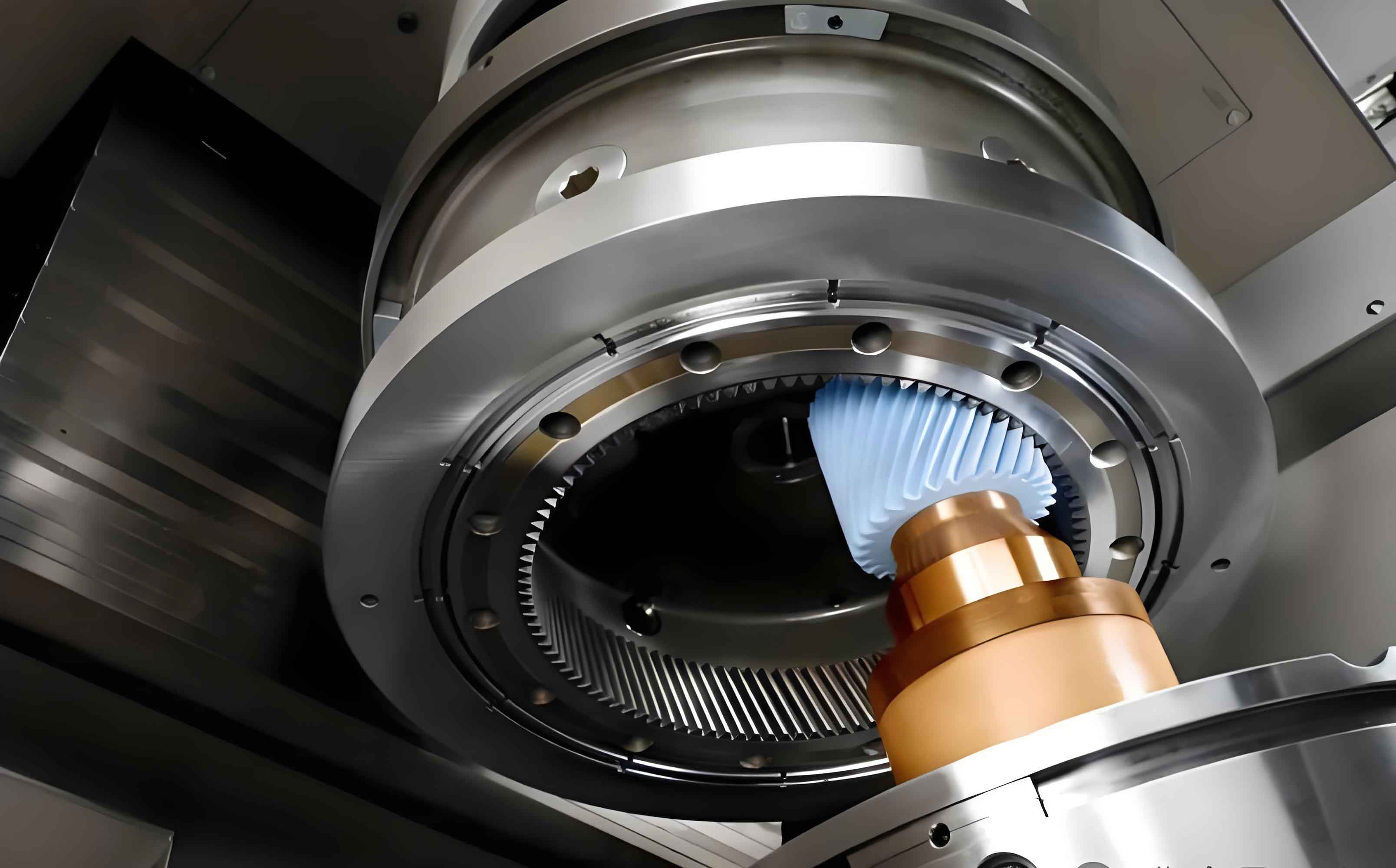
In the pursuit of high-performance gear transmissions, the final finishing process is paramount. Among the various techniques available for hardening gears, gear honing has emerged as a highly efficient and economically viable solution. This abrasive machining process is characterized by its ability to improve the surface integrity and geometric accuracy of hardened gears without inducing detrimental thermal damage. The process involves the meshing of a honing wheel, typically coated with abrasive grains like Cubic Boron Nitride (CBN), with the hardened gear workpiece. As they rotate in conjugate motion with an added axial reciprocation of the workpiece, the abrasive particles on the honing wheel’s surface remove material through a controlled micro-cutting and sliding action. The fundamental mechanism of material removal in gear honing is not one of high-speed cutting, but rather of precise abrasion at relatively low speeds. This characteristic is a key advantage, as it avoids the generation of excessive heat and the associated risks of re-hardening, tempering, or residual tensile stresses that can compromise the fatigue life of the gear. Consequently, gear honing is extensively employed for correcting heat treatment distortions, enhancing surface finish, and improving noise behavior in final gear assemblies.
While the benefits of gear honing for improving overall gear quality are well-documented, a nuanced challenge persists: the inconsistency of surface quality across a single tooth flank. It is frequently observed that after honing, the surface roughness and texture can vary significantly from the tooth root to the tooth tip. This non-uniformity can lead to uneven wear patterns during service, potentially localizing stress and initiating premature failure, thereby undermining the very performance gains the process seeks to achieve. The root cause of this inconsistency lies in the fundamental kinematics of the process. Unlike a simple turning operation with a constant cutting speed, the relative sliding velocity between the honing wheel and the workpiece in gear honing is a complex function of the contact point’s position along the path of contact. This velocity, which we term the effective cutting or honing speed, is not constant. Its magnitude and direction vary continuously as the meshing proceeds from the start to the end of active profile. Therefore, a deep understanding of the distribution characteristics of this cutting speed along the line of contact is not merely an academic exercise but a practical necessity. It holds the key to optimizing the gear honing process for superior and consistent surface quality, guiding the development of honing tools, and ultimately extending the service life of the finished components.
Theoretical Derivation of Cutting Speed at the Contact Point
The core of analyzing the gear honing process kinematically is to derive a precise mathematical expression for the relative velocity vector at the instantaneous point of contact between the honing wheel and the gear workpiece. This relative velocity is the vector sum of two primary components: one arising from the rotational meshing motion and the other from the axial reciprocation of the workpiece. To establish this, we employ principles of gear meshing theory and coordinate transformation.
We define two right-handed coordinate systems rigidly connected to the honing wheel and the workpiece, denoted as $S_1(o_1, x_1, y_1, z_1)$ and $S_2(o_2, x_2, y_2, z_2)$, respectively. A fixed global coordinate system $S_f(o_f, x_f, y_f, z_f)$ is also established. The honing wheel rotates about its axis with an angular velocity $\vec{\omega}_1$, and the workpiece rotates with $\vec{\omega}_2$. The axes are crossed at a shaft angle $\Sigma$. The workpiece also translates axially with a velocity $\vec{V}_a = \dot{h}\vec{k}$, where $\dot{h}$ is the axial feed rate.
The total relative velocity (cutting speed) $\vec{V}_{12}$ at a contact point $M$ can be expressed as the sum of the velocity due to rotation and the velocity due to axial feed, transformed into the appropriate coordinate system. A transformation matrix $K_{\phi’_1}$ is used, where $\phi’_1$ is related to the honing wheel’s rotational position and its basic geometry, effectively simplifying to its transverse pressure angle $\alpha’_{t1}$.
$$ \vec{V}_{12} = K_{\phi’_1} \left( \vec{V}^{( \varphi)}_{12} + \vec{V}^{( h)}_{12} \right) $$
The axial feed contribution in the fixed system is straightforward:
$$ \vec{V}^{( h)}_{12} = \dot{h} \vec{k} $$
The rotational relative velocity $\vec{V}^{( \varphi)}_{12}$ is derived from the rigid body motion. If $\vec{R’}_1$ is the position vector of contact point $M$ in $S_1$, and the center distance vector is $\vec{a}$, then:
$$ \vec{V}^{( \varphi)}_{12} = \vec{\omega}_1 \times \vec{R’}_1 – \vec{\omega}_2 \times (\vec{a} + \vec{R’}_1) $$
Given the gear ratio $i_{21} = \omega_2 / \omega_1$ and considering the axes configuration and opposite rotational directions, this cross-product can be expanded. Representing angular velocities in the fixed frame and expressing the cross-product in determinant form with unit vectors $\vec{i}, \vec{j}, \vec{k}$ leads to:
$$
\vec{V}^{( \varphi)}_{12} = \begin{vmatrix}
\vec{i} & \vec{j} & \vec{k} \\
i_{21}\omega_1 \cos\Sigma & 0 & i_{21}\omega_1 \sin\Sigma – i_{21}\omega_1 \\
x’_1 & y’_1 – a & z’_1
\end{vmatrix}
$$
Evaluating this determinant and combining it into a homogeneous coordinate form for easier transformation yields:
$$
\begin{bmatrix} V^{( \varphi)}_{12x} \\ V^{( \varphi)}_{12y} \\ V^{( \varphi)}_{12z} \\ V^{( \varphi)}_{12t} \end{bmatrix} = \begin{bmatrix}
i_{21} \omega_1 (y’_1 – a)(1 – \sin\Sigma) \\
i_{21} \omega_1 z’_1 + i_{21} \omega_1 x’_1 (1 – \sin\Sigma) \\
i_{21} \omega_1 (y’_1 – a) \cos\Sigma \\
t
\end{bmatrix}
$$
Applying the coordinate transformation $K_{\phi’_1} = K_{\alpha’_{t1}}$, which is a basic rotation matrix about the z-axis by angle $\alpha’_{t1}$, and adding the axial feed component, we get the cutting speed in the honing wheel coordinate system:
$$
\begin{bmatrix} V_{12x} \\ V_{12y} \\ V_{12z} \\ V_{12t} \end{bmatrix} =
\begin{bmatrix}
\cos\alpha’_{t1} & -\sin\alpha’_{t1} & 0 & 0 \\
\sin\alpha’_{t1} & \cos\alpha’_{t1} & 0 & 0 \\
0 & 0 & 1 & 0 \\
0 & 0 & 0 & 1
\end{bmatrix}
\cdot
\begin{bmatrix}
i_{21} \omega_1 (y’_1 – a)(1 – \sin\Sigma) \\
i_{21} \omega_1 z’_1 + i_{21} \omega_1 x’_1 (1 – \sin\Sigma) \\
i_{21} \omega_1 (y’_1 – a) \cos\Sigma \\
t
\end{bmatrix}
+
\begin{bmatrix}
0 \\
0 \\
\dot{h} \\
0
\end{bmatrix}
$$
The final step is to substitute the parametric equations of the honing wheel’s helical involute surface into this expression. The coordinates $(x’_1, y’_1, z’_1)$ of a point on the honing wheel surface can be expressed in terms of its base circle radius $r_{b1}$, the involute roll angle $\gamma’$, and its helix parameter $p$ (related to lead). Performing this substitution and simplification results in the comprehensive vector equation for the cutting speed in gear honing as a function of the contact point’s geometric parameter $\gamma’$:
$$
\vec{V}_{12}(\gamma’) =
\begin{bmatrix}
r_{b1}(\cos\alpha’_{t1} + \gamma’\sin\alpha’_{t1})(i_{21}\omega_1\cos\Sigma – \omega_1) – i_{21}\omega_1 a \cos\Sigma – \dot{h}\sin\Sigma \\
r_{b1}(\sin\alpha’_{t1} – \gamma’\cos\alpha’_{t1})(i_{21}\omega_1\cos\Sigma – \omega_1) + i_{21}\omega_1 r_{b1}^2 (\gamma’ – \tan\alpha’_{t1}) \sin\Sigma / p \\
– r_{b1}(\cos\alpha’_{t1} + \gamma’\sin\alpha’_{t1}) i_{21}\omega_1\sin\Sigma + i_{21}\omega_1 a \sin\Sigma – \dot{h}\cos\Sigma \\
t
\end{bmatrix}
$$
This equation is central to understanding gear honing kinematics. It explicitly shows that the cutting speed $\vec{V}_{12}$ is not a constant but a function of the parameter $\gamma’$, which defines the position of the contact point along the tooth profile from the root to the tip.
Distribution Characteristics of the Cutting Speed
The derived equation allows us to analyze the distribution pattern of the effective cutting speed magnitude along the full path of contact during gear honing. This speed is synthesized from three sliding components: sliding along the profile direction (profile sliding), sliding along the lead direction (lead sliding), and the component from the axial feed motion. The relative direction of these components reverses at the pitch point, leading to the characteristic “herringbone” or crossed-hatch pattern observed on honed gear teeth surfaces.
The variation in speed magnitude, however, has a direct consequence on the efficiency of material removal and the resulting surface finish. To illustrate this, let us consider a specific honing wheel and workpiece pair with the parameters listed in the table below:
| Parameter | Honing Wheel | Workpiece Gear |
|---|---|---|
| Module | $m_n = 3$ mm | $m = 3$ mm |
| Number of Teeth | $z_1 = 71$ | $z_2 = 26$ |
| Helix Angle | $\beta_1 = 14^\circ 4’34”$ | $\beta_2 = 0^\circ$ (Spur) |
| Pressure Angle | $\alpha = 20^\circ$ | $\alpha = 20^\circ$ |
| Face Width | 25 mm | 33 mm |
Using the derived formula and computational analysis (e.g., in MATLAB), the magnitude of $|\vec{V}_{12}|$ can be plotted against the contact position for different honing wheel rotational speeds $n_y$ (where $\omega_1 = 2\pi n_y / 60$). For a typical axial feed rate of about 12 mm/s, the contribution of $\dot{h}$ is relatively small and can be neglected for this speed magnitude analysis. The resulting distribution curves reveal a critical trend:
$$ |\vec{V}_{12}(\gamma’)| = f(n_y, \gamma’) $$
The analysis clearly demonstrates that the cutting speed is variable. For a given honing wheel speed, the speed is highest near the honing wheel’s tooth tip region (which contacts the workpiece root), moderately high near the honing wheel’s root region (which contacts the workpiece tip), and reaches a minimum in the vicinity of the pitch point. This non-uniform distribution is intrinsic to the conjugate meshing action in gear honing.
More importantly, the analysis shows that as the honing wheel speed $n_y$ increases, the disparity in cutting speed across the tooth flank becomes more pronounced. The difference between the maximum and minimum speed values on the contact line grows larger. This implies that the conditions for abrasive cutting action—the pressure, sliding distance, and energy input per unit time—vary more significantly across the tooth profile at higher speeds. Consequently, one can hypothesize that this would lead to a greater disparity in surface finish quality from the root to the tip of the workpiece tooth. This theoretical insight forms the basis for experimental investigation in the gear honing process.
Experimental Investigation and Correlation with Surface Quality
To validate the theoretical relationship between cutting speed distribution and surface quality in gear honing, a controlled experiment was designed. The workpiece gears were standard involute spur gears made from steel, case-hardened to a surface hardness of HRC 61-63. To establish a consistent baseline, all workpieces were first precision ground to achieve uniform initial surface quality. The honing trials were conducted on a dedicated gear honing machine (e.g., Y4650 type). The honing wheel was a helical gear with a CBN-plated surface, using abrasive grains of approximately 120 grit size (average diameter ~0.15 mm). A constant honing pressure of 100 N was applied. Each workpiece was processed with a standard cycle of 12 reciprocating strokes in each rotational direction.
Post-honing, the workpieces were sectioned along the tooth face width to allow for detailed surface metrology. Surface roughness measurements were taken using a precision profilometer (e.g., Mahr type) at standardized locations on the tooth flank: at the tip, near the pitch line, and at the root. Multiple readings were taken at each location, and the average arithmetic mean roughness ($R_a$) value was calculated. This procedure was repeated for workpieces honed at different honing wheel rotational speeds. The core experimental data is summarized in the table below, showing the average $R_a$ values for different honing speeds ($n_y$) at the three critical tooth locations.
| Honing Speed $n_y$ (rpm) | Tooth Tip $R_a$ (μm) | Pitch Line $R_a$ (μm) | Tooth Root $R_a$ (μm) |
|---|---|---|---|
| 200 | 1.44 | 1.46 | 1.42 |
| 400 | 1.01 | 1.07 | 0.96 |
| 650 | 0.64 | 0.75 | 0.61 |
The data reveals several key findings that align with and confirm the theoretical predictions of gear honing behavior:
- Overall Improvement with Speed: For any given location (tip, pitch, root), the surface roughness $R_a$ decreases as the honing wheel speed increases. Higher cutting speeds generally promote a more effective cutting action by the CBN abrasives, leading to a better final surface finish. This is expressed as a general trend: $R_a(n_y) \propto 1/n_y^{\kappa}$ where $\kappa$ is a positive exponent.
- Existence of Profile Non-Uniformity: At any fixed honing speed, the surface roughness is not constant across the tooth profile. The pitch line region consistently shows the highest $R_a$ value, while the root and tip regions are lower and often quite similar to each other. This directly correlates with the theoretical cutting speed distribution, where the speed is minimum near the pitch point, potentially leading to less effective material removal and plastic smoothing action compared to the faster-moving contact zones at the tip and root.
- Amplification of Non-Uniformity with Speed: Most significantly, the difference in surface roughness between the pitch line and the other regions increases with honing speed. We can quantify this disparity $\Delta R_a$. For instance:
- At $n_y = 200$ rpm: $\Delta R_a^{pitch-tip} = 0.02 \mu m$, $\Delta R_a^{pitch-root} = 0.04 \mu m$.
- At $n_y = 400$ rpm: $\Delta R_a^{pitch-tip} = 0.06 \mu m$, $\Delta R_a^{pitch-root} = 0.11 \mu m$.
- At $n_y = 650$ rpm: $\Delta R_a^{pitch-tip} = 0.11 \mu m$, $\Delta R_a^{pitch-root} = 0.14 \mu m$.
This trend of increasing $\Delta R_a$ with increasing $n_y$ confirms the theoretical prediction that speed amplifies the inherent non-uniformity of the cutting action in gear honing. While the average surface quality improves, the consistency across the tooth profile deteriorates.
The experimental results provide strong empirical evidence that the distribution of cutting speed, derived from the fundamental kinematics of gear honing, is the primary factor governing the consistency of surface finish on a single tooth flank. The minimum speed at the pitch point results in a comparatively poorer finish, and this effect becomes more marked as the overall honing speed is raised.
Conclusions and Implications for Gear Honing Practice
This investigation into the kinematics and surface generation in gear honing leads to several important conclusions that have direct implications for process optimization and tool design:
- The cutting speed in gear honing is a spatially variable vector, precisely described by the derived function $\vec{V}_{12}(\gamma’)$. Its magnitude is not constant along the line of contact, exhibiting a characteristic distribution with minima near the pitch region and maxima towards the ends of the active profile.
- The non-uniform distribution of this cutting speed is the fundamental cause of inconsistent surface roughness ($R_a$) across the tooth flank of the workpiece after gear honing. The region corresponding to the pitch point, experiencing the lowest effective cutting speed, typically exhibits the highest roughness.
- Increasing the honing wheel rotational speed, while generally beneficial for improving the average surface finish, simultaneously exacerbates the disparity in surface quality between different points on the same tooth. The roughness difference $\Delta R_a$ between the pitch line and the root/tip increases with speed.
- Therefore, to prioritize surface quality consistency across the tooth profile—which is critical for uniform load distribution and wear in service—the gear honing process should be conducted at a relatively lower rotational speed. This finding provides a clear guideline for process parameter selection, favoring consistency over maximum finishing potential when both are required.
- A comprehensive understanding of post-honing surface quality requires looking beyond just cutting speed. Future research and process development must adopt a holistic view, integrating the effects of other critical factors such as applied honing force (pressure), the grain size and distribution of the abrasive coating on the honing wheel, the dynamic variations in contact conditions, and even the acceleration components during the reciprocating stroke.
In essence, this work underscores that gear honing is a process where kinematics dictates micro-scale results. By mastering the relationship between the inherent speed distribution and the resulting surface texture, manufacturers can make informed decisions to tailor the gear honing process for specific performance outcomes, whether the priority is ultimate smoothness, profile consistency, or a balanced compromise, thereby unlocking the full potential of this efficient hard gear finishing technology.