
The continuous pursuit of higher precision, superior surface integrity, and extended service life for power transmission components has driven the evolution of gear finishing technologies. Among these, gear honing has established itself as a critical process for refining hardened gear teeth. The recent integration of ultrasonic vibration into this process represents a significant technological leap. This article delves into the principles, mechanisms, and advantages of Ultrasonic Assisted Gear Honing, providing a comprehensive analysis of this advanced manufacturing technique.
Conventional gear honing is a finishing process where a honing tool, or “hone,” impregnated with abrasive grains (such as CBN or diamond), meshes with a hardened gear under crossed-axes or parallel-axes configuration. Material removal occurs through the sliding motion and pressure between the abrasive grains and the gear tooth flanks. While effective, traditional honing can face challenges with efficiency, surface quality consistency, and the finishing of complex or high-hardness materials. The superposition of high-frequency, low-amplitude ultrasonic vibration onto the workpiece or the tool fundamentally alters the cutting mechanics, leading to a process known as Ultrasonic Vibration Assisted Gear Honing.
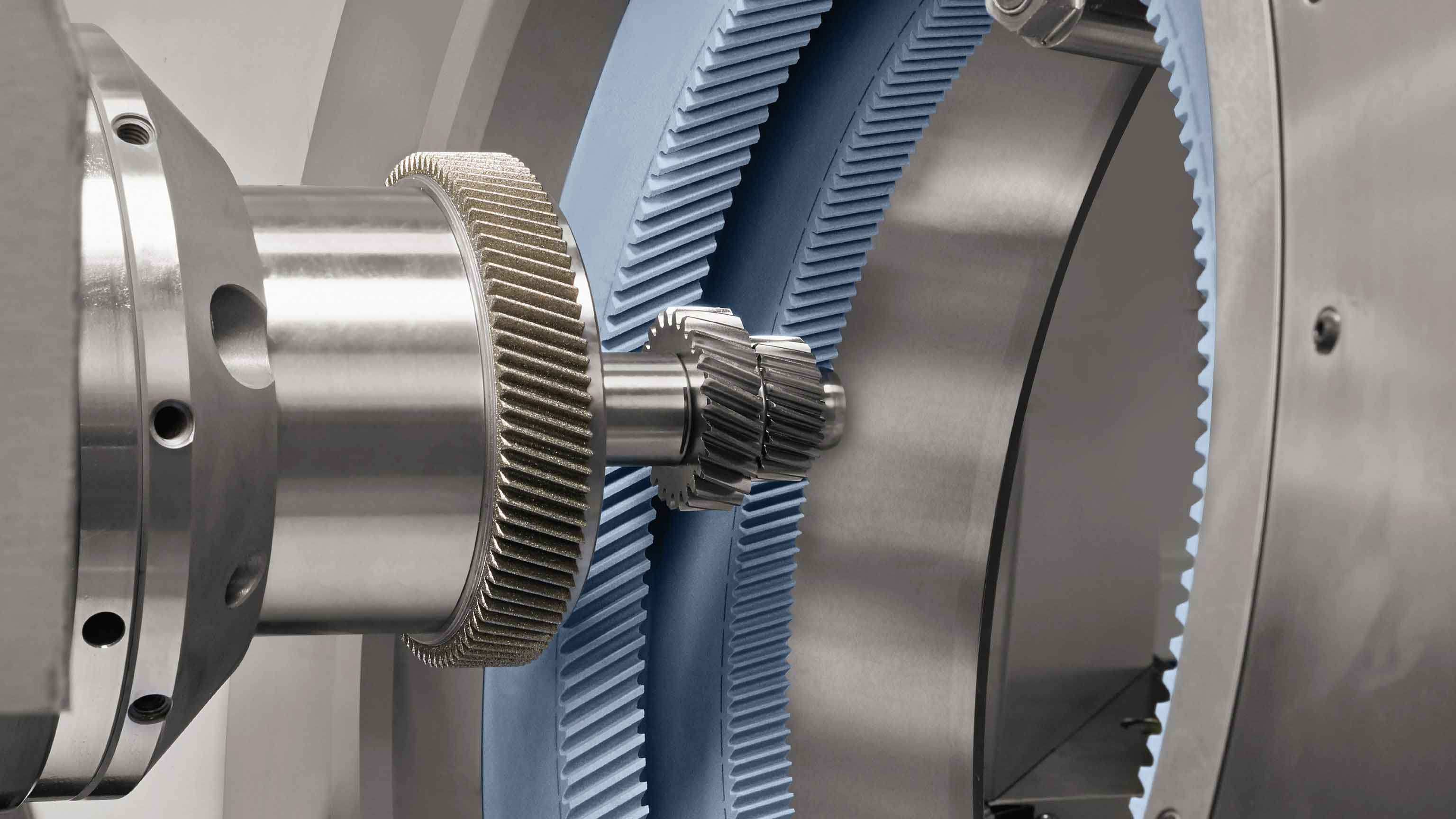
The core of ultrasonic gear honing lies in its unique kinematics. In a typical parallel-axis setup, the honing wheel (CBN plated) rotates actively, driving the workpiece gear. Simultaneously, the workpiece is subjected to ultrasonic-frequency mechanical vibrations along its axial direction. This superimposition creates a complex, three-dimensional cutting path for each abrasive grain on the honing wheel.
The engagement in ultrasonic gear honing typically employs a dual-flank, zero-backlash meshing condition. This is essential to ensure simultaneous contact and processing of both the drive and coast sides of the gear tooth. Maintaining the correct theoretical center distance is paramount. Deviation from this optimal distance shifts the contact lines towards the tooth tips and roots, and can cause misalignment between the contact lines on the two flanks. This leads to imbalanced cutting forces, potential edge contact, degradation of gear accuracy, and even tool damage. Therefore, achieving and maintaining precise, zero-backlash meshing is the foundational requirement for effective ultrasonic gear honing.
The motion of a point on the workpiece tooth surface is a combination of its rotational motion (due to meshing) and its harmonic ultrasonic vibration. If we consider the workpiece vibration along its axis (z-direction) with amplitude \( A \) and angular frequency \( \omega_u = 2\pi f_u \), where \( f_u \) is the ultrasonic frequency (typically 20-40 kHz), the position of a point can be described. The resulting path of a single abrasive grain relative to the workpiece surface is not a simple straight line but a wave-like pattern. The kinematics can be summarized in the following table:
| Motion Component | Description | Typical Parameters |
|---|---|---|
| Rotational Meshing | Generates relative sliding velocity (\(v_{sliding}\)) along the tooth profile. Zero at the pitch line, increasing towards tip and root. | Honing wheel speed: 500-2000 rpm; Gear ratio defined by tooth counts. |
| Ultrasonic Vibration | Superimposes high-frequency oscillation (\(v_{vib}\)) along the tooth face width (axial direction). | Frequency \(f_u\): 20-40 kHz; Amplitude \(A\): 1-20 μm. |
| Resultant Cutting Velocity | Vector sum of \(v_{sliding}\) and \(v_{vib}\). Magnitude and direction change continuously during the honing cycle. | $$v_{cut} = \sqrt{v_{sliding}^2 + v_{vib}^2}$$ where \(v_{vib} = A \omega_u \cos(\omega_u t)\). |
This complex velocity field is a key differentiator of ultrasonic gear honing. The periodic separation between the abrasive grain and the workpiece chip (due to vibration) drastically improves cutting fluid penetration, reducing friction, heat generation, and the likelihood of built-up edge formation.
The cutting mechanism in ultrasonic gear honing is a synergistic combination of abrasive machining and dynamic impact. Each CBN grain acts as a micro-cutting tool. The ultrasonic vibration imparts high acceleration to these grains, transforming the process from purely continuous shear to a series of micro-impacts.
- Reduction in Cutting Force and Specific Energy: The high-frequency impact causes localized micro-cracking in the workpiece material ahead of the grain. This pre-conditioning reduces the plastic deformation resistance. Furthermore, the periodic disengagement reduces the average friction force. The net effect is a significant reduction in tangential honing force and specific cutting energy compared to conventional gear honing.
- Enhanced Material Removal Mechanism: Material removal occurs through:
- Micro-Hammering: The grain impacts the surface, causing fatigue and breaking brittle micro-protrusions.
- Ploughing with Fracture: The grain plows through the material, but the ultrasonic energy aids in crack propagation, facilitating chip formation.
- Acoustic Softening: The ultrasonic energy absorbed by the material’s lattice can increase dislocation mobility, temporarily reducing flow stress and making cutting easier.
- Improved Surface Generation: The altered chip formation mechanism, combined with better cooling, leads to surfaces with:
- Lower roughness (Ra, Rz).
- Reduced surface and sub-surface damage (less white layer, smaller plastic deformation zone).
- Favorable residual compressive stresses.
The following table contrasts the primary mechanisms of conventional and ultrasonic gear honing:
| Aspect | Conventional Gear Honing | Ultrasonic Gear Honing |
|---|---|---|
| Grain-Workpiece Contact | Near-continuous, high friction. | Intermittent, reduced average friction. |
| Primary Removal Mode | Continuous plastic shear and ploughing. | Micro-impact, fatigue, and assisted shear. |
| Cutting Fluid Action | Mostly cooling, limited lubrication at interface. | Effective penetration and lubrication during separation periods. |
| Surface Integrity | Good, but risk of thermal damage at high parameters. | Superior, with lower roughness and less thermal/mechanical damage. |
A geometric analysis provides further insight into the gear honing process, particularly the instantaneous contact conditions. Consider the engagement between the honing wheel and the workpiece gear as two cylinders with varying radii of curvature at the contact point. For a given point of contact, let \( R \) be the radius of curvature of the honing wheel tooth, and \( r \) be the radius of curvature of the workpiece gear tooth. The nominal center distance is \( R + r \). During cutting, the honing wheel is pressed into the workpiece with a total depth of engagement (or interference) \( \Delta \).
The geometric contact length \( l_c \) along the tooth profile is a critical parameter, as it influences the number of active abrasive grains and the pressure distribution. It can be derived from the geometry of two circles in contact with interference. For small angles, the contact arc length is approximately:
$$ l_c \approx \sqrt{ \frac{2 \Delta}{\frac{1}{R} + \frac{1}{r}} } = \sqrt{ 2 \Delta \rho_{eff} } $$
where \( \rho_{eff} = \frac{R r}{R + r} \) is the effective radius of curvature. A more precise formula considering the arc is:
$$ l_c = \rho_{eff} \cdot \alpha $$
where \( \alpha = \sqrt{ \frac{2 \Delta}{\rho_{eff}} } \).
Therefore,
$$ l_c = \sqrt{ 2 \Delta \rho_{eff} } = \sqrt{ 2 \Delta \cdot \frac{R r}{R + r} } $$
This shows that the contact length increases with the square root of the depth of engagement \( \Delta \) and the effective radius. In ultrasonic gear honing, the apparent \( \Delta \) is dynamically modulated by the vibration, affecting the instantaneous contact conditions.
Furthermore, the distribution of abrasive grains on the honing wheel surface is crucial. Key geometric parameters of the abrasive layer include:
- Mean Grain Spacing (W): The average center-to-center distance between adjacent active abrasive grains. It is typically 1 to 2 times the average grain diameter \(d_g\).
- Continuous Cutting Edge Spacing (a_c): The distance between successive cutting edges along the direction of motion. It depends on the mean grain spacing and the average width \(b\) of the cutting track: $$ a_c \approx \frac{W^2}{b} $$
In ultrasonic gear honing, the vibration alters the effective cutting track width \(b\), thereby influencing \(a_c\) and the undeformed chip thickness model. The theoretical maximum undeformed chip thickness \(h_{max}\) for a grain can be modeled as a function of process parameters:
$$ h_{max} \propto \left( \frac{v_w}{N \cdot C} \right)^{\frac{1}{2}} \left( \frac{a_c}{l_c} \right)^{\frac{1}{2}} $$
Where \(v_w\) is the relative workpiece speed (enhanced by vibration), \(N\) is the honing wheel rotational speed, and \(C\) is the active grain density on the wheel surface. The ultrasonic vibration increases \(v_w\), which would tend to increase \(h_{max}\), but it also promotes more grains to cut effectively and reduces the required force, allowing for a more controlled and finer cut in practice.
To fully harness the benefits of ultrasonic gear honing, the design and preparation of the honing tool are critical. The tool, often a helical gear plated with CBN or diamond abrasives, must not only possess high geometric accuracy to transfer its profile to the workpiece but also be compatible with the dynamic process.
- Abrasive Selection: Cubic Boron Nitride (CBN) is the premier choice for honing hardened steel gears (typically > 45 HRC). Its extreme hardness and thermal stability prevent rapid wear and thermal degradation. The grain size (e.g., #100 to #400 mesh) is selected based on the desired balance between material removal rate and final surface finish.
- Tool Bonding: A metal bond (often nickel-based) is commonly used for gear honing tools. It provides strong grain retention for the high forces involved while allowing controlled wear to expose new sharp grains. The bond hardness and porosity are tailored to the specific application.
- Profile Accuracy and Modification: The honing wheel profile is precisely manufactured and often includes intentional modifications (tip and root relief, crowning) to generate desired contact patterns on the finished gear and compensate for potential system deflections during the honing process.
- Dynamic Considerations: The honing wheel must have good dynamic balance to avoid unwanted vibrations that could interfere with the controlled ultrasonic vibration. Its structural rigidity is also vital to maintain mesh accuracy under cutting forces.
The performance of ultrasonic gear honing is governed by a complex interplay of parameters. Optimizing these parameters is key to achieving high quality and efficiency.
| Parameter Category | Key Variables | Influence on Process |
|---|---|---|
| Vibration Parameters | Frequency (\(f_u\)), Amplitude (\(A\)) | Higher \(f_u\) increases impact rate; Higher \(A\) increases velocity component and separation effect, but excessive \(A\) may cause instability. Optimal range is critical. |
| Kinematic Parameters | Honing wheel speed (\(n_h\)), Axial stroke speed (\(v_a\)), Center distance (\(a\)) | Control the basic cutting speed, coverage, and meshing pressure. \(a\) directly controls the interference \(\Delta\) and contact pattern. |
| Abrasive Tool Parameters | Grain size, concentration, bond type, tool profile | Define cutting aggressiveness, tool life, and the geometric accuracy transferred to the workpiece. |
| Process Control Parameters | Honing pressure/force, Honing time/number of strokes, Cutting fluid (type, pressure, flow) | Pressure influences removal rate and surface finish. Time determines final stock removal. Cutting fluid is crucial for cooling, chip evacuation, and lubrication in the dynamic process. |
The interaction can be modeled through the material removal rate (MRR) and surface roughness. A simplified model for MRR in ultrasonic gear honing might consider the dynamic depth of cut:
$$ MRR \propto N_{active} \cdot v_{cut,avg} \cdot h_{avg} \cdot b $$
Where \(N_{active}\) is the number of active grains, \(v_{cut,avg}\) is the average resultant cutting velocity, \(h_{avg}\) is the average undeformed chip thickness, and \(b\) is the chip width. The ultrasonic vibration positively affects \(v_{cut,avg}\) and may increase the effective \(N_{active}\) by promoting grain engagement.
Surface roughness (\(R_a\)) tends to follow a relationship inversely proportional to vibration parameters and directly proportional to grain size under optimized conditions:
$$ R_a \propto \frac{k \cdot d_g^\alpha}{f_u^\beta \cdot A^\gamma} $$
where \(k\) is a constant, \(d_g\) is grain diameter, and \(\alpha, \beta, \gamma\) are positive exponents determined empirically.
When benchmarked against other gear finishing processes, ultrasonic gear honing carves out a distinct niche, particularly for high-volume production of precision hardened gears.
| Process | Typical Application | Advantages | Limitations | Comparison with Ultrasonic Honing |
|---|---|---|---|---|
| Grinding | High-precision, low-volume, form/ generating grind. | Excellent accuracy, good surface finish. | High cost, thermal damage risk, slower for full tooth flank. | Ultrasonic honing is faster for full flank finishing, less thermal risk, lower tooling cost, but may have slightly lower form accuracy limit. |
| Conventional Honing | Correcting heat treat distortions, improving surface finish. | Good corrective ability, efficient, simple machine setup. | Limited improvement in roughness vs. grinding, tool wear. | Ultrasonic version offers significantly better surface finish, lower forces, reduced tool wear, and higher material removal rates. |
| Hard Skiving/Hobbing | Dry, high-speed finishing of hardened gears. | Very high productivity, dry process. | High machine tool investment, tool cost, limited to certain hardness ranges. | Ultrasonic honing provides better surface integrity and is more suitable for final super-finishing after skiving/hobbing. |
| Superfinishing (e.g., PPT) | Ultra-high surface finish for noise reduction. | Exceptional low roughness, creates beneficial surface structure. | Very low stock removal, mostly a polishing process. | Ultrasonic honing can remove more stock while still achieving excellent finish, acting as a combined finishing and super-finishing step. |
The primary advantages of ultrasonic gear honing are:
- Superior Surface Quality: Lower Ra values, non-directional texture, compressive stresses.
- High Efficiency: Increased material removal rate due to dynamic effects.
- Reduced Tool Wear: Intermittent cutting and lower forces extend honing wheel life.
- Improved Geometrical Accuracy: The continuous line contact in parallel-axis honing effectively corrects lead and profile deviations.
- Versatility: Suitable for a wide range of gear modules and hardness levels.
Ultrasonic gear honing has found successful application in the mass production of automotive transmission gears (both passenger car and heavy-duty), aerospace gearing, and high-performance industrial gearboxes. It is particularly valuable for finishing gears after case hardening, where it efficiently removes heat treat distortions, improves flank geometry, and creates a superior running surface that contributes to lower noise, higher efficiency, and longer fatigue life.
The future development of ultrasonic gear honing is likely to focus on several fronts:
- Adaptive Process Control: Integrating in-process sensors (force, acoustic emission, vibration) with AI/ML algorithms to dynamically adjust parameters (pressure, amplitude) for consistent quality and optimal tool life.
- Tooling Innovation: Development of engineered abrasive structures and advanced bond systems specifically designed for the dynamic loads of ultrasonic honing.
- Dry or MQL Honing: Leveraging the improved chip evacuation and lower heat generation of ultrasonic assistance to minimize or eliminate cutting fluid usage, enhancing sustainability.
- Hybrid Processes: Combining ultrasonic vibration with other energy-assisted methods (e.g., laser assistance) for processing advanced, difficult-to-machine gear materials.
- Micro-Gear Honing: Scaling down the technology for the precision finishing of micro-gears used in miniaturized devices.
In conclusion, ultrasonic assisted gear honing represents a transformative advancement in gear finishing technology. By fundamentally altering the cutting mechanics through high-frequency vibration, it delivers a compelling combination of high efficiency, exceptional surface integrity, and improved process capability. The detailed understanding of its engagement characteristics, cutting mechanisms, and geometric interactions provides the theoretical foundation for optimizing this process. As machine tool technology, tooling, and control systems continue to evolve, ultrasonic gear honing is poised to become an increasingly dominant solution for meeting the ever-growing demands for high-performance, quiet, and durable gear components across critical industries.