
Gear transmission stands as one of the most fundamental and widely utilized methods for power transmission in modern industry. Its advantages, including accurate transmission ratio, high efficiency, wide power range, compact structure, and long service life, have cemented its role in automotive, aerospace, marine, and numerous other sectors. High-speed gears, typically defined as those with a pitch line velocity exceeding 25 m/s or rotational speeds above 3600 rpm, are critical components in high-performance drivetrains, such as those found in new energy vehicles. These gears operate under demanding conditions that require exceptional reliability, low noise emission, and resistance to wear. Meeting these stringent requirements necessitates advanced finishing processes that go beyond conventional machining.
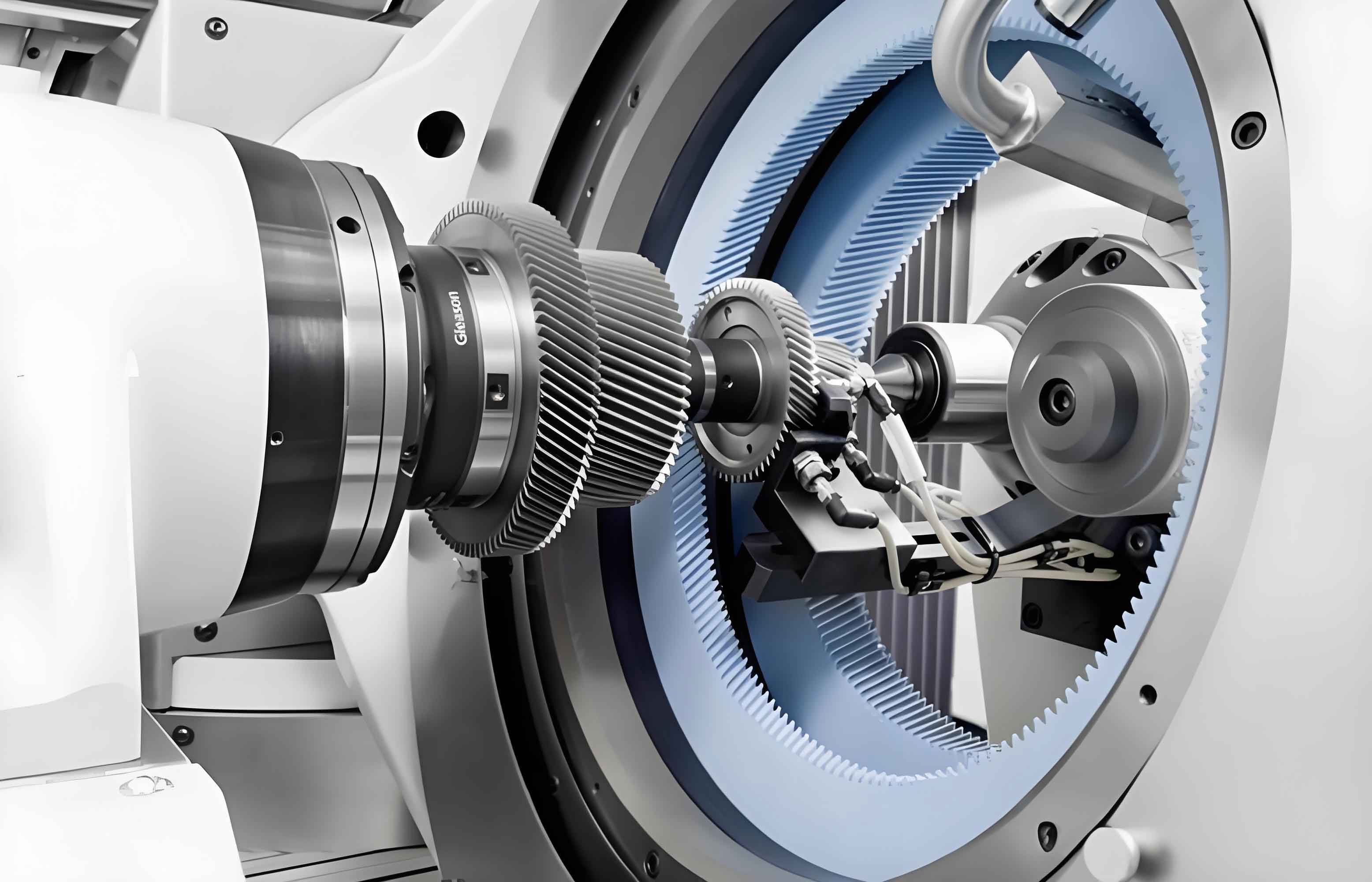
Among various finishing techniques, internal gear honing, particularly power honing, has emerged as a highly efficient and high-performance solution. This process utilizes a honing wheel, essentially an internal helical gear coated with abrasive particles, to finish hardened gear teeth. Compared to traditional gear grinding, gear honing offers several distinct benefits: higher processing efficiency, the generation of favorable compressive residual stresses on the tooth flanks, a significant reduction in gear meshing noise (often eliminating ‘gear whine’), and an extended service life. However, the core technologies and high-end equipment for internal gear power honing have long been monopolized by a few Western corporations, creating a technological bottleneck for the manufacturing industries in many countries, including China. Furthermore, process design in many domestic workshops often relies heavily on empirical knowledge rather than theoretical models, limiting process optimization and consistency.
Therefore, revealing the underlying mechanisms of the gear honing process, establishing accurate predictive models, and comprehensively evaluating the resulting surface integrity are of paramount importance. Such research not only guides the improvement of existing honing processes but also provides a crucial theoretical foundation for the independent research and development of advanced honing machines. This article delves into the modeling of the internal gear power honing process for high-speed gears and the characterization of the resultant surface integrity, aiming to bridge the gap between empirical practice and scientific understanding.
1. Mechanistic Analysis of the Internal Gear Power Honing Process
To establish a foundational model, a precise understanding of the process kinematics and material removal mechanism is essential. The internal gear power honing process involves the forced meshing between a workpiece external helical gear and an internal helical honing wheel, with their axes arranged at a specific crossed-axis angle. This configuration is kinematically equivalent to the meshing of an internal gear pair with non-parallel, non-intersecting axes.
1.1 Kinematic Analysis and Meshing Theory
The relative motion between the honing wheel and the workpiece gear can be described by establishing coordinate systems. Let us define a fixed coordinate system \( S_{wf}(O_{wf}-x_{wf}-y_{wf}-z_{wf}) \) attached to the workpiece and a fixed coordinate system \( S_{hf}(O_{hf}-x_{hf}-y_{hf}-z_{hf}) \) attached to the honing wheel. The center distance is denoted as \( d \), and the crossed-axis angle is \( \gamma \), which equals the difference between the helix angles of the honing wheel (\( \beta_h \)) and the workpiece (\( \beta_w \)): \( \gamma = \beta_h – \beta_w \). The transformation matrix between these fixed systems is:
$$
M_{wf,hf} = \begin{bmatrix}
1 & 0 & 0 & d\\
0 & \cos\gamma & -\sin\gamma & 0\\
0 & \sin\gamma & \cos\gamma & 0\\
0 & 0 & 0 & 1
\end{bmatrix}
$$
The surface of the workpiece gear in its moving coordinate system \( S_w \) is a standard involute helicoid, represented by the position vector \( \mathbf{r}_w(\zeta, \eta) \):
$$
\mathbf{r}_w(\zeta, \eta) = \begin{bmatrix}
r_b \cos(\zeta + \eta) + r_b \zeta \sin(\zeta + \eta) \\
r_b \sin(\zeta + \eta) – r_b \zeta \cos(\zeta + \eta) \\
p_w \eta
\end{bmatrix}
$$
where \( r_b \) is the base circle radius, \( \zeta \) is the involute roll angle parameter, \( \eta \) is the parameter along the tooth width, and \( p_w \) is the lead of the helix.
According to the fundamental theorem of conjugate surfaces, the necessary condition for contact (the meshing equation) is that the relative velocity at the contact point is perpendicular to the common normal vector. This leads to the equation:
$$
\mathbf{v}^{(12)} \cdot \mathbf{n} = 0
$$
Where \( \mathbf{v}^{(12)} \) is the relative velocity vector between the workpiece (1) and the honing wheel (2) at the potential contact point, and \( \mathbf{n} \) is the common unit normal vector. Expanding this condition in the fixed coordinate system yields a functional relationship between the surface parameters and the rotation angle of the workpiece, \( \phi_w(t) \). This relationship, combined with the surface equation \( \mathbf{r}_w \), defines the family of contact lines on the honing wheel surface—a process known as the first envelope, which theoretically defines the ideal form of the honing wheel tooth flank. The subsequent process, where this honing wheel surface machines the workpiece, is the second envelope. For the generated workpiece surface to be a perfect involute helicoid, the first envelope must be designed so that no new lines of contact appear during the second envelope, a condition satisfied by proper selection of the crossed-axis angle \( \gamma \).
1.2 Material Removal Mechanism in Gear Honing
Material removal in gear honing is achieved through the micro-cutting action of abrasive particles bonded to the honing wheel’s surface. Unlike single-point cutting tools, the honing process involves a multitude of irregularly shaped, randomly oriented abrasive grains. The interaction between a single abrasive grain and the workpiece material can be categorized into three regimes: sliding/rubbing, ploughing, and cutting.
In the rubbing regime, the grain elastically deforms the workpiece surface without forming a chip. In the ploughing regime, the grain pressure causes plastic deformation, displacing material to the sides and front of the grain path, forming ridges alongside a groove. Only in the cutting regime is material removed as a micro-chip. The relative proportion of grains engaged in each regime depends on factors like grain protrusion height, honing force, and material properties. The low cutting speeds characteristic of gear honing (often below 10 m/s) and the high hardness of the case-hardened gear substrate promote significant plastic deformation during the ploughing phase. This results in the final surface topography being a complex superposition of numerous micro-grooves with associated plastic side flow and ridges.
The characteristics of the abrasive grains are crucial. Grains are characterized by their shape, size (grit number), spacing, and protrusion height. For modeling purposes, grain shapes are often simplified to geometric primitives. Two common assumptions are:
- Conical grains: Representing sharp, unworn grains with a semi-apical angle \( \theta \).
- Spherical grains: Representing worn or rounded grains with a radius \( R_g \).
The average spacing between active grains, \( \Delta \), is a critical parameter influencing surface roughness and can be estimated based on the wheel’s grit size and structure number. The force acting on the workpiece tooth during gear honing can be resolved into components: tangential (or circumferential) \( F_x \), radial \( F_y \), and axial \( F_z \). These forces drive the abrasive grains into the workpiece material, enabling the micro-cutting action.
2. Development of a Digital Model for the Gear Honing Process
Building upon the kinematic and mechanistic foundations, a digital model can be constructed to simulate the generation of surface texture and predict surface roughness.
2.1 Digital Modeling of Surface Texture Considering Abrasive Cutting Traces
The core idea is to simulate the trajectory of individual abrasive grains on the workpiece surface and update a discretized model of the gear tooth flank accordingly. The tooth flank surface is first discretized into a grid of points \( P_{i,j} \), defined by their position vectors derived from the involute helicoid equation.
For a given set of process parameters (wheel speed \( \omega_h \), workpiece speed \( \omega_w \), crossed-axis angle \( \gamma \), center distance \( d \)), the kinematic model provides the relative velocity vector \( \mathbf{v}_{i,j} \) at each discrete point \( P_{i,j} \) at a specific instant of meshing. The path of a grain, assumed to be initially at a meshing contact point \( B_e^{(0)} \), is then traced. As the honing wheel rotates by a small angle \( \Delta\phi_h \), the grain’s mapped position on the workpiece moves to \( B_e^{(1)} \):
$$
B_e^{(1)} = B_e^{(0)} + \mathbf{v}_{e}^{(0)} \cdot \Delta t
$$
where \( \Delta t = \Delta\phi_h / \omega_h \). The line segment from \( B_e^{(0)} \) to \( B_e^{(1)} \) represents a potential cutting trace, \( \Gamma_e^{(1)} \). This trace is then checked for interference with the discrete surface points. If a discrete point \( P_{i,j} \) is found to be within the interference zone of the grain (determined by the grain’s geometry and depth of cut), its position is updated to reflect the material removal, effectively carving a micro-groove. This process is repeated for multiple small rotation increments until the grain exits the meshing zone, generating a complete cutting trace \( \Gamma_e \). By simulating a large number of such traces from different grains entering the contact zone at different times, the cumulative effect—the honed surface texture—is generated. The texture orientation at any point can be characterized by the angle \( \alpha \) between the local cutting trace direction and the profile (involute) direction of the tooth.
The simulated texture typically exhibits a “fish-bone” or cross-hatched pattern, which is a hallmark of the gear honing process. The orientation angle \( \alpha \) varies across the tooth flank, often reaching a maximum near the pitch line and decreasing towards the tip and root.
2.2 Numerical Model for Surface Roughness Incorporating Elastic-Plastic Deformation
Surface roughness is a critical quantitative measure of surface integrity. Predicting it requires modeling not just the groove geometry from cutting but also the associated plastic side flow (pile-up). The maximum theoretical peak-to-valley height created by a single grain, ignoring pile-up, can be estimated by models derived from grinding theory. A model adapted for gear honing considers the local kinematics and geometry:
$$
H_0 = \left( \frac{3}{16} \cdot \frac{1}{\tan \theta} \cdot p \cdot \Delta^{2q} \right)^{\frac{1}{3}}
$$
where \( \theta \) is the grain semi-apical angle, \( \Delta \) is the average grain spacing, \( q \) is a coefficient related to grain shape and distribution, and \( p \) is a process condition coefficient. For gear honing, \( p \) is modified to account for the relative velocities at the contact point along the texture direction (\( v_{w,\Gamma} \), \( v_{h,\Gamma} \)) and the local effective radii of curvature (\( \rho_w \), \( \rho_h \)):
$$
p = \frac{1}{c} \cdot \left( \frac{1}{v_{w,\Gamma}} – \frac{1}{v_{h,\Gamma}} \right) \cdot \frac{\rho_w \rho_h}{\rho_h – \rho_w}
$$
Here, \( c \) is related to the number of honing strokes. However, \( H_0 \) only represents the groove depth. Due to plastic deformation, a significant portion of the displaced material forms ridges of height \( h_p \) on either side of the groove. The material removal rate \( \tau \) (ratio of chip volume to total groove volume) is less than 1. For both conical and spherical grain assumptions, the pile-up height can be related to the maximum groove depth. For a conical grain, the relationship is \( h_p = (1-\tau) H_0 / 2 \). A similar proportional relationship holds for spherical grains under certain geometric simplifications. Therefore, the total peak-to-valley height \( H \) accounting for plastic deformation is:
$$
H = H_0 + h_p
$$
Finally, the arithmetic average roughness \( R_a \) can be empirically correlated to this total height. A common relationship is \( R_a \approx 0.256 \cdot H \). This model allows for the prediction of \( R_a \) distribution across the gear tooth flank based on process parameters, wheel specification, and workpiece material properties.
| Parameter | Symbol | Description | Typical Influence on \( R_a \) |
|---|---|---|---|
| Crossed-Axis Angle | \( \gamma \) | Angle between honing wheel and workpiece axes. | Increasing \( \gamma \) generally increases relative sliding speed, enhancing cutting action and reducing \( R_a \). |
| Honing Wheel Speed | \( n_h \) or \( \omega_h \) | Rotational speed of the honing wheel. | Higher speed increases the number of active grain engagements per unit time, typically reducing \( R_a \). |
| Workpiece Speed | \( n_w \) or \( \omega_w \) | Rotational speed of the workpiece gear. | Affects the kinematics and relative speed; optimal ratio with \( n_h \) is important. |
| Grain Size (Grit Number) | – | Average size of abrasive particles. | Finer grit (higher number) leads to smaller \( \Delta \) and potentially lower \( R_a \), but may affect cutting efficiency. |
| Grain Shape Assumption | \( \theta \) or \( R_g \) | Modeled as conical (angle \( \theta \)) or spherical (radius \( R_g \)). | Sharper grains (smaller \( \theta \)) produce deeper grooves and higher \( R_a \). Spherical grains produce shallower, wider grooves. |
| Material Removal Rate | \( \tau \) | Fraction of groove volume removed as chip. | Lower \( \tau \) implies more ploughing, higher pile-up \( h_p \), and increased \( R_a \). |
3. Experimental Investigation and Surface Integrity Characterization
To validate the developed models and characterize the surface integrity, experimental studies were conducted on high-speed gears made from 20CrMnTiH carburizing steel, typical for automotive applications.
3.1 Experimental Setup and Validation
Gear honing experiments were performed on a Fässler HMX-400 internal gear honing machine. The workpiece gears were first rough machined by gear hobbing, then case-hardened. Some samples underwent a preliminary rough grinding operation before honing to control the stock allowance precisely. The honing parameters varied included honing wheel speed, workpiece speed, and the crossed-axis angle (altered by using honing wheels with different helix angles).
The surface texture was examined using a 3D optical microscope, confirming the characteristic cross-hatched pattern of gear honing. The surface roughness \( R_a \) was measured at multiple locations along the profile and lead directions using a laser confocal microscope. The measured \( R_a \) values were compared against the predictions from the numerical model. The model based on the spherical grain assumption showed better agreement with experimental data, with a maximum relative error of 8.67%, compared to the conical grain model. This suggests that under the conditions of fine finishing with low stock removal, the abrasive grains behave more like rounded (spherical) indentors due to wear and the dominant ploughing mechanism.
The digital texture model was also validated. The simulated texture successfully reproduced the fish-bone pattern, and the calculated texture orientation angle \( \alpha \) varied across the tooth flank, matching the trend observed in experiments—increasing from the root and tip towards the pitch line.
3.2 Analysis of Surface Texture and Roughness
The influence of process parameters on surface characteristics was analyzed both experimentally and through the digital model.
Texture Orientation: The crossed-axis angle \( \gamma \) is the primary factor controlling texture orientation. The model reveals that when \( \gamma \) is near 0° (parallel axes), the texture aligns almost purely with the profile direction. As \( \gamma \) increases, the texture direction angle \( \alpha \) increases, creating the desirable cross-hatch. For very large angles, the texture can become predominantly aligned with the lead direction. An optimal range (e.g., 5° to 10°) exists to create a texture orientation that is optimally orthogonal to the contact lines during gear meshing, which is known to be beneficial for noise reduction.
Surface Roughness: The analysis confirms that surface roughness \( R_a \) decreases with an increase in the crossed-axis angle \( \gamma \) and with an increase in honing wheel speed \( n_h \). The effect of the honing wheel’s number of teeth (which slightly alters the speed ratio) was minor. The roughness distribution was not uniform across the tooth flank, often showing a specific pattern from root to tip, which the model was able to capture.
Comparison with Gear Grinding: A key comparison was made with gears finished by蜗杆砂轮磨齿 (worm gear grinding). Grinding typically produces parallel, straight scratches along the lead direction. In contrast, gear honing produces the cross-hatched pattern. This difference in surface texture has a direct impact on functional performance. The honed texture promotes better lubricant entrapment and creates a surface where the directional grooves are less likely to interlock during meshing, contributing to lower friction and noise generation.
| Characteristic | Gear Honing | Gear Grinding | Functional Implication |
|---|---|---|---|
| Surface Texture Pattern | Cross-hatched, “fish-bone” pattern. | Primarily straight, parallel scratches along tooth lead. | Honed texture improves oil film retention and reduces directional interlocking, lowering noise. |
| Typical Roughness \( R_a \) | Can achieve comparable levels (e.g., 0.2-0.8 μm). Often slightly higher than finely ground surfaces. | Can achieve very low values (e.g., < 0.4 μm). | Both can meet functional requirements. Honing may trade off ultimate smoothness for other benefits. |
| Residual Stress State | Generates high compressive residual stresses near the surface. | Can generate compressive stresses, but risk of tensile stresses or “grinding burns” if parameters are incorrect. | Compressive stresses from honing greatly enhance fatigue life (contact and bending). |
| Subsurface Alteration | Generally produces a thinner white layer/thermally affected zone. | Risk of a thicker thermally affected zone or rehardened white layer if cooling is insufficient. | Honing is a “cooler” process, better preserving the base material’s metallurgy. |
| Process Efficiency | Very high material removal rate for finishing; short cycle times. | Slower than honing for stock removal; high precision. | Honing is highly efficient for finishing hardened gears. |
3.3 Analysis of Microhardness and Subsurface Integrity
Microhardness testing (Vickers hardness, HV1) was performed on cross-sectional samples from honed and ground gears to evaluate subsurface changes.
The results indicated that the gear honing process produces a significant surface work-hardening effect. The hardness at the immediate surface (within 0.1 mm) of honed gears was higher than that of ground gears from the same batch. This increase is attributed to the severe plastic deformation induced by the abrasive grains during the ploughing and cutting actions, which refines the microstructure near the surface.
Furthermore, the hardness gradient beneath the surface was generally more gradual for honed gears compared to some ground gears. Grinding, especially if thermal effects are not perfectly controlled, can sometimes create a steep hardness drop or a softened layer due to tempering, followed by the core hardness. The honing process, being a lower-temperature process, produced a more uniform transition from the hardened case to the core. This uniformity in hardness distribution contributes to better resistance against spalling and pitting fatigue.
Metallographic examination of the subsurface revealed that both processes created a plastically deformed “white layer,” but its thickness was generally smaller in honed samples (~130 μm) compared to the ground sample examined (~171 μm), corroborating the lower thermal impact of honing.
4. Conclusion and Outlook
This research has systematically investigated the internal gear power honing process for high-speed gears, focusing on mechanistic modeling and surface integrity characterization. The key conclusions are as follows:
- Process Mechanism: The kinematics of internal gear honing were successfully described using the theory of conjugate gear meshing with crossed axes. The material removal is governed by the micro-cutting, ploughing, and rubbing actions of abrasive grains, with plastic deformation playing a major role in forming the final surface topography.
- Digital Modeling: A digital model was established that simulates the generation of the characteristic cross-hatched surface texture by tracking abrasive grain trajectories. Furthermore, a numerical model for predicting surface roughness (\( R_a \)) was developed, incorporating the effects of grain geometry, process kinematics, and, crucially, the elastic-plastic pile-up of material. The model validation showed good agreement with experimental measurements, particularly under the spherical grain assumption.
- Surface Integrity: Experimental analysis confirmed that the crossed-axis angle \( \gamma \) is the dominant parameter controlling surface texture orientation. Surface roughness decreases with increasing \( \gamma \) and honing wheel speed. Compared to gear grinding, gear honing produces a superior surface texture for noise reduction, generates high compressive residual stresses, induces beneficial surface work-hardening, and results in a more favorable subsurface hardness gradient with less thermal damage risk.
The findings provide a theoretical foundation for optimizing the gear honing process. For high-speed, low-noise applications like new energy vehicle gearboxes, internal gear power honing presents a compelling alternative to traditional grinding, offering a combination of high efficiency, excellent surface integrity, and enhanced functional performance.
Future work should focus on several areas to extend this research: developing more sophisticated 3D abrasive grain models that account for actual wear and distribution; integrating the surface topography model with gear contact dynamics models to predict functional performance (noise, friction, wear) directly; and establishing intelligent optimization frameworks to automatically determine the optimal set of honing parameters for a desired set of surface integrity targets. Advancing these areas will further solidify gear honing as a science-driven manufacturing process essential for next-generation high-performance gear production.