
The pursuit of quieter and more efficient power transmission systems, particularly in the rapidly evolving field of new energy vehicles, has placed significant emphasis on the finishing processes of gear components. Among these, internal gear power honing stands out as a critical finishing operation for hardened gears. This process is highly regarded not only for its efficiency but also for its unique ability to generate a specific, non-parallel arc-like surface texture on the gear tooth flanks. This distinct texture pattern is instrumental in enhancing oil retention and, more importantly, in mitigating periodic resonances that contribute to gear whine—a common issue with parallel grinding textures. Therefore, gaining a deep understanding of the formation mechanism of this honing texture and developing methods to predict and actively control it are paramount for optimizing gear performance and noise characteristics. This article delves into the mechanics of internal gear power honing, establishes predictive models for the surface texture, and proposes a methodology for its active control through strategic manipulation of key process parameters.
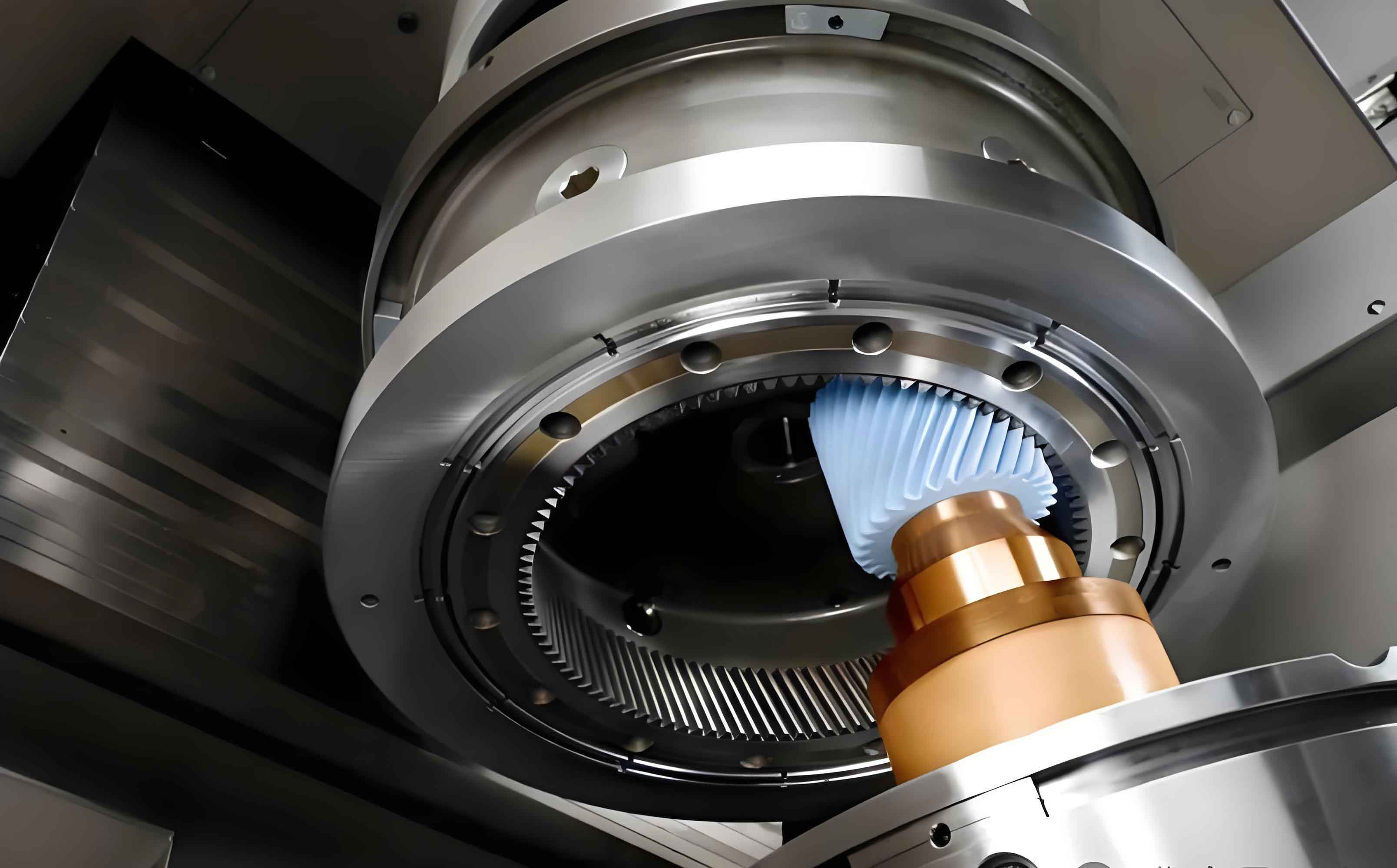
The core of the gear honing process lies in the relative motion between the abrasive-laden internal honing wheel and the external workpiece gear, which are arranged with crossed axes. The honing texture is essentially the macroscopic accumulation of countless microscopic cutting traces left by the abrasive grains. The direction of each trace at a given point on the tooth surface is dictated by the instantaneous honing speed vector at that contact point. During gear honing, the total honing speed at a contact point, denoted as $v_C$, is not unidirectional. It is the vector sum of two orthogonal components: the profile speed $v_H$ and the lead speed $v_L$. The profile speed results from the relative rolling motion of the conjugate gear surfaces, while the lead speed arises from the sliding action along the tooth flank due to the crossed-axis arrangement. Their magnitudes can be expressed as:
$$ v_H = 2\pi(\rho_W n_W – \rho_H n_H) $$
$$ v_L = 2\pi n_W r_W \frac{\sin\Sigma}{\cos\beta_H} $$
$$ v_C = \sqrt{v_L^2 + v_H^2} $$
Here, $\rho_W$ and $\rho_H$ are the radii of curvature at the contact point in a transverse section for the workpiece and honing wheel, respectively; $n_W$ and $n_H$ are their rotational speeds; $r_W$ is the distance from the contact point to the workpiece axis; $\Sigma$ is the crossed-axis angle; and $\beta_H$ is the helical angle of the honing wheel. A key observation is that $v_H$ becomes zero at the pitch line of the workpiece and reverses direction on either side, whereas $v_L$ varies with $r_W$. This combination results in a honing speed $v_C$ whose magnitude and direction are unique at every point on the tooth flank, thereby generating the characteristic curved texture pattern intrinsic to the gear honing process.
To predict the specific texture pattern, it is essential to model the line of contact between the honing wheel and the workpiece tooth surface at any given instant. The mathematical derivation begins by establishing the spatial coordinate systems for both the workpiece gear and the honing wheel. Let $S_W(O_Wx_Wy_Wz_W)$ and $S_H(O_Hx_Hy_Hz_H)$ be the fixed coordinate systems attached to the workpiece and honing wheel, respectively. Their associated rotating coordinate systems are $S_1(O_1x_1y_1z_1)$ and $S_2(O_2x_2y_2z_2)$. The transformation matrices between these systems, accounting for rotations $\phi_1$, $\phi_2$ and the center distance $a$ and crossed-axis angle $\Sigma$, are:
$$ M_{1W} = \begin{bmatrix}
\cos\phi_1 & \sin\phi_1 & 0 & 0 \\
-\sin\phi_1 & \cos\phi_1 & 0 & 0 \\
0 & 0 & 1 & 0 \\
0 & 0 & 0 & 1
\end{bmatrix}, \quad M_{H2} = \begin{bmatrix}
\cos\phi_2 & -\sin\phi_2 & 0 & 0 \\
\sin\phi_2 & \cos\phi_2 & 0 & 0 \\
0 & 0 & 1 & 0 \\
0 & 0 & 0 & 1
\end{bmatrix} $$
$$ M_{WH} = \begin{bmatrix}
1 & 0 & 0 & -a \\
0 & \cos\Sigma & -\sin\Sigma & 0 \\
0 & \sin\Sigma & \cos\Sigma & 0 \\
0 & 0 & 0 & 1
\end{bmatrix} $$
$$ M_{12} = M_{1W} M_{WH} M_{H2} $$
The workpiece tooth surface is a standard involute helicoid. In its own coordinate system $S_1$, its equation is given by:
$$ \mathbf{r}_1 = \begin{bmatrix} x_1 \\ y_1 \\ z_1 \end{bmatrix} = \begin{bmatrix}
r_{b1}\cos(\sigma_0 + \theta + \lambda) + r_{b1}\lambda\sin(\sigma_0 + \theta + \lambda) \\
r_{b1}\sin(\sigma_0 + \theta + \lambda) – r_{b1}\lambda\cos(\sigma_0 + \theta + \lambda) \\
p\theta
\end{bmatrix} $$
where $r_{b1}$ is the base circle radius, $\sigma_0$ is the start angle of the involute, $\theta$ is the helical increment, $\lambda$ is the involute roll angle, and $p$ is the helix parameter.
The honing wheel surface is generated as the envelope of a master gear (dressing tool) with matching geometry, establishing a conjugate, line-contact relationship with the workpiece. The fundamental conjugate condition states that the relative velocity vector $\mathbf{v}_{12}$ at a contact point must be perpendicular to the common surface normal vector $\mathbf{n}$ at that point:
$$ \mathbf{v}_{12} \cdot \mathbf{n} = 0 $$
The relative velocity is calculated in the workpiece fixed coordinate system $S_W$ as $\mathbf{v}_{12} = \boldsymbol{\omega}_W \times \mathbf{r}_W – \boldsymbol{\omega}_H \times \mathbf{r}_H$, where $\boldsymbol{\omega}_W$ and $\boldsymbol{\omega}_H$ are the angular velocity vectors. The normal vector is derived from the partial derivatives of the surface equation: $\mathbf{n} = \frac{\partial \mathbf{r}_W}{\partial \lambda} \times \frac{\partial \mathbf{r}_W}{\partial \theta}$, with $\mathbf{r}_W = M_{W1} \mathbf{r}_1$. Substituting these into the conjugate equation yields the meshing equation. The complete mathematical model for the instantaneous contact line on the workpiece surface is thus described by the simultaneous equations of the tooth surface and the meshing condition:
$$
\begin{cases}
x_1 = r_{b1}\cos(\sigma_0 + \theta + \lambda) + r_{b1}\lambda\sin(\sigma_0 + \theta + \lambda) \\
y_1 = r_{b1}\sin(\sigma_0 + \theta + \lambda) – r_{b1}\lambda\cos(\sigma_0 + \theta + \lambda) \\
z_1 = p\theta \\
(ap\cos\Sigma – r_{b1}^2\sin\Sigma)\cos(\sigma_0 + \theta + \lambda + \phi_1) + (\theta p – \lambda r_{b1}^2)\sin\Sigma \sin(\sigma_0 + \theta + \lambda + \phi_1) + (p\cos\Sigma – a\sin\Sigma – i_{12}p)r_{b1} = 0
\end{cases}
$$
where $i_{12}$ is the transmission ratio. By calculating a sequence of these contact lines throughout the mesh cycle and tracing the honing speed direction at discrete points along them, a comprehensive predictive model for the gear honing texture pattern can be generated.
A significant practical challenge in gear honing is the wear of the honing wheel’s abrasive surface, which necessitates periodic dressing to restore its cutting ability. The dressing process directly alters the key geometrical parameters governing the honing kinematics, namely the effective center distance $a$ and the crossed-axis angle $\Sigma$. Two primary dressing strategies are employed: fixed crossed-axis angle dressing and variable crossed-axis angle dressing. The latter is more sophisticated and aims to extend the honing wheel’s life. In this method, as the dressing tool performs a radial feed (changing $a$ by $\Delta a$), the honing head is simultaneously swung to adjust $\Sigma$ according to a specific functional relationship designed to maintain optimal honing conditions. This relationship can be derived from the fundamental gear kinematics:
$$ \Sigma’ = \arccos\left( \frac{\omega_1}{\omega_2} \frac{r_{01}\cos\beta_{01}}{r_{01} + a + \Delta a} \right) – \beta_{01} $$
where $r_{01}$ and $\beta_{01}$ are the pitch radius and helix angle of the workpiece during honing, respectively. Regardless of the method, the post-dressing changes in $a$ and $\Sigma$ inevitably influence the resulting workpiece texture, making an understanding of their effects crucial for maintaining consistent quality across production batches and throughout the honing wheel’s lifespan.
| Dressing Strategy | Primary Change | Effect on Honing Speed Magnitude | Effect on Honing Speed Direction / Pitch Line |
|---|---|---|---|
| Fixed Σ (Radial Dressing) | Increase in Center Distance ($a$) | Overall speed increases. Speed difference from root to tip becomes larger. Minimum speed point shifts towards the tip. | Pitch line location moves significantly towards the tip. Texture pattern curvature and distribution change markedly. |
| Variable Σ (Synchronized Dressing) | Coordinated increase in $a$ and adjustment of $\Sigma$ | Overall speed increases. Speed difference from root to tip is minimized or reduced. | Pitch line location remains largely constant. Texture pattern remains stable with minimal alteration. |
The analysis of honing speed clearly demonstrates that the parameters $a$ and $\Sigma$ are the primary levers for controlling the texture. The direction of the honing speed vector, which dictates the local texture orientation, is highly sensitive to these parameters. By strategically adjusting them, one can actively control the distribution and evolution trend of the gear honing texture. This leads to the proposed active texture control methodology. Conceptually, the state of the honing process can be mapped onto a two-dimensional plane defined by the center distance $a$ and the crossed-axis angle $\Sigma$. Any specific combination ($a_0$, $\Sigma_0$) yields a unique texture pattern characterized by, for example, the angle between the texture trace and the tooth lead direction at a reference point like the effective root. To transition to a different desired texture, one can follow distinct paths on this control plane:
Path 1 (Radial Adjustment): Keeping $\Sigma$ constant and only adjusting $a$ (e.g., via radial dressing) moves the operating point horizontally. This shifts the pitch line, typically moving it towards the tooth tip as $a$ increases, and generally reduces the curvature of the texture arcs, making them straighter.
Path 2 (Helical Angle/Σ Adjustment): Keeping $a$ constant and adjusting $\Sigma$ (which is linked to a change in the effective honing wheel helix angle $\beta_H$) moves the operating point vertically. This can significantly alter the lead speed component $v_L$, changing the texture angle without drastically relocating the pitch line.
Path 3 (Coordinated Adjustment): Simultaneously adjusting both $a$ and $\Sigma$ along a specific function, such as the one derived for variable-axis dressing, allows movement along a diagonal path. This path is designed to maintain a constant pitch line location, thereby preserving the core texture distribution pattern while accommodating necessary process changes like wheel wear compensation.
Therefore, through the appropriate selection and control of the honing wheel’s design parameters (like base helix angle and profile shift) and the subsequent process parameters ($a$ and $\Sigma$), the honing operator or machine control system can navigate to any desired point within a feasible region on this control plane, effectively achieving a targeted surface texture for the gear honing process.
To validate the predictive models and the proposed control methodology, experimental gear honing tests were conducted. Workpiece gears with identical specifications were honed under different sets of process parameters, corresponding to different points on the control plane. The basic parameters for the experimental setup are summarized below:
| Component | Parameter | Value |
|---|---|---|
| Workpiece Gear | Module | 1.65 mm |
| Number of Teeth | 29 | |
| Pressure Angle | 19° | |
| Helix Angle | -22° | |
| Profile Shift Coefficient | 0.2727 | |
| Honing Wheel 1 | Module | 1.65 mm |
| Number of Teeth | 151 | |
| Pressure Angle | 19° | |
| Helix Angle | -30° | |
| Honing Wheel 2 | Module | 1.65 mm |
| Number of Teeth | 151 | |
| Pressure Angle | 19° | |
| Helix Angle | -35.9° |
The three-dimensional topography of the honed tooth flanks was then examined using advanced microscopy. The results were compared against the texture patterns predicted by the mathematical model for the corresponding parameter sets.
| Process Parameters | Predicted Texture Model (Highlighted Trend) | Experimental 3D Topography Result | Quantitative Comparison (Angle at Tip) |
|---|---|---|---|
| Case 1: Crossed-axis angle $\Sigma = 8°$ Center distance $a = 118$ mm |
The predicted model shows a distinct curved texture. The red guideline indicates the general trend, forming an angle of approximately 49° relative to the tooth lead direction at the tip region. | The actual honed surface exhibits a clear arc-like texture. The dominant direction of the texture traces aligns closely with the predicted red guideline. | Predicted Angle: 49° Measured Angle: ~50° Error: ~2.0% |
| Case 2: Crossed-axis angle $\Sigma = 13.9°$ Center distance $a = 128$ mm |
For this different parameter set, the predictive model generates a texture with a notably different curvature. The guideline at the tip now forms a shallower angle of about 30° to the lead direction. | The experimentally obtained surface texture confirms the change. The texture arcs are less curved compared to Case 1, and their orientation matches the 30° guideline from the model. | Predicted Angle: 30° Measured Angle: ~31° Error: ~3.3% |
The high degree of consistency between the predicted texture trends and the experimentally observed surface topographies, with angular errors of only 1° in both cases, provides strong validation for the accuracy of the contact line and honing speed models. Furthermore, it conclusively demonstrates the efficacy of the proposed active control method. By deliberately selecting different combinations of the crossed-axis angle $\Sigma$ and center distance $a$, we successfully produced gears with measurably different, yet predictable, surface texture patterns. This capability is fundamental for tailoring the gear honing process to meet specific functional requirements, such as optimizing for noise reduction or lubrication performance.
In conclusion, this investigation into internal gear power honing has elucidated the fundamental mechanism behind the formation of its characteristic surface texture. The texture is a direct manifestation of the spatially varying honing speed vector, which is decomposed into profile and lead components. A rigorous mathematical model based on conjugate gear theory was developed to simulate the contact lines and predict the resulting texture pattern. The critical influence of honing wheel dressing on the governing process parameters—center distance and crossed-axis angle—was analyzed, highlighting their impact on both the magnitude and direction of the honing speed. Based on this understanding, a novel methodology for the active control of the gear honing texture was proposed. This method treats the center distance and crossed-axis angle as control variables to navigate a process control plane, enabling deliberate manipulation of the texture’s distribution and its evolution over the honing wheel’s lifecycle. Experimental validation confirmed that gears honed with different parameter sets exhibited textures that closely matched the model’s predictions. This work establishes a solid theoretical foundation and a practical framework for designing and optimizing gear surface textures via the gear honing process, ultimately contributing to the production of high-performance, low-noise transmission systems.