
In my extensive research on precision gear finishing, I have focused on the challenges associated with achieving high accuracy in hard gear tooth surfaces. Traditional methods such as shaving, cold rolling, or external gear honing often struggle to consistently meet the required precision levels, particularly for gears with 6 to 7 grade accuracy per standards like JB. While imported grinding machines can achieve this, they are inefficient and costly, and even domestic grinders like the Y7132A face difficulties in meeting critical tolerances such as pitch accuracy and noise reduction. Therefore, I have dedicated considerable effort to exploring internal gear honing as a superior alternative. My experiments and theoretical analyses confirm that internal gear honing significantly enhances precision, offers high efficiency, low cost, and is exceptionally suitable for hard tooth surface finishing. This article delves into the mechanisms, parametric optimizations, and experimental validations of internal gear honing, emphasizing its advantages over external gear honing through detailed formulas, tables, and practical insights.
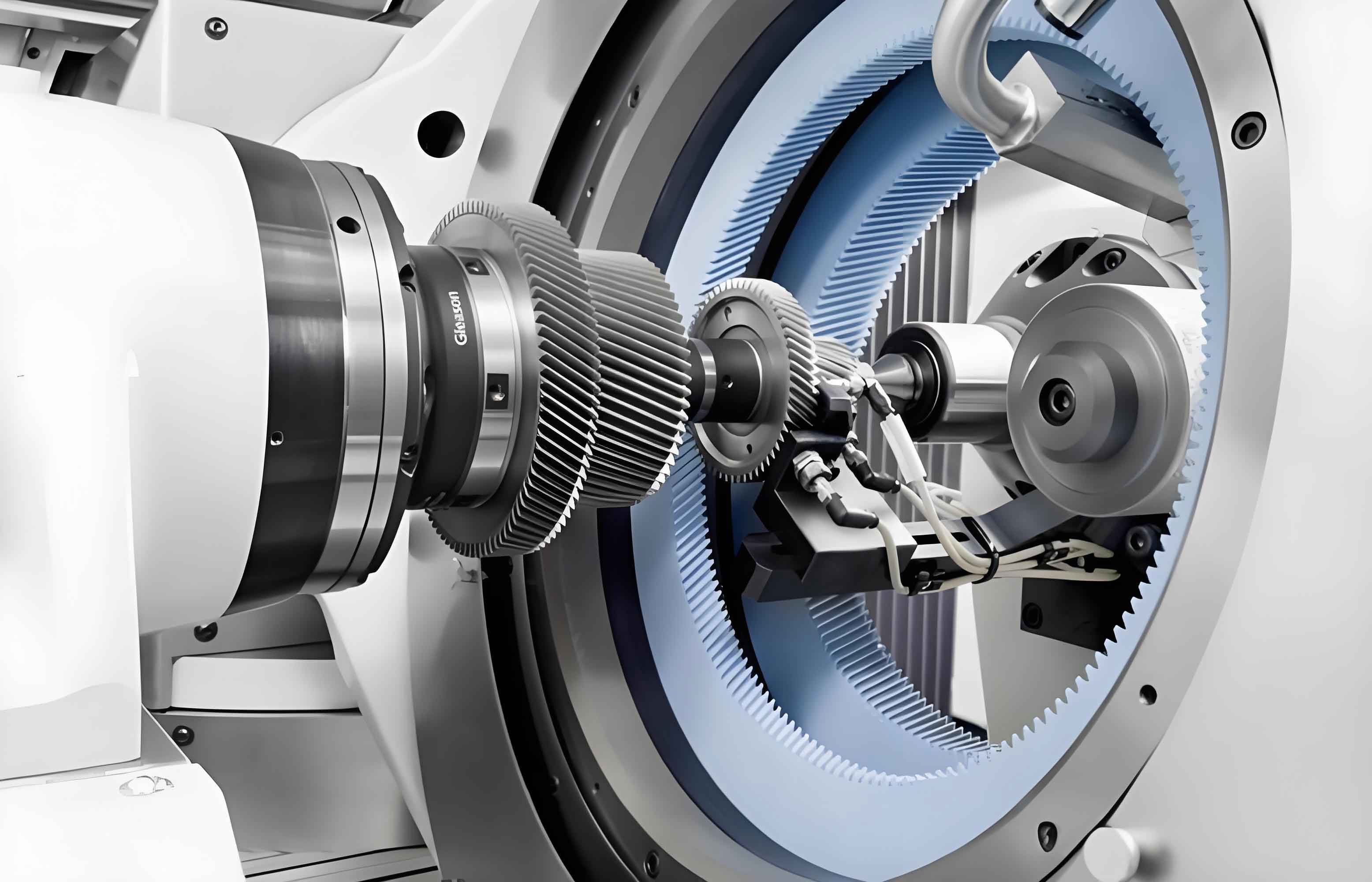
The mechanism of internal gear honing involves a crossed-axis helical gear pair consisting of an internal honing wheel and an external gear (spur or helical). In this process, the honing wheel acts as the driving element, while the workpiece follows in an internal meshing arrangement under a no-backlash, variable-pressure mode. Theoretically, an internal involute helical gear pair is prone to meshing interference, often referred to as “搭角接触” or overlapping contact, which increases with the shaft crossing angle. However, I have found that this interference can be advantageous if controlled properly. By adjusting the honing wheel and workpiece parameters, it facilitates convex profile modifications on the tooth flanks, thereby improving gear accuracy. The key distinctions of internal gear honing compared to external gear honing lie in its higher contact ratio, lower relative sliding velocity, and more uniform contact stress distribution, which I will analyze in detail.
First, let’s consider the contact ratio, a critical factor in gear honing. For a crossed-axis helical gear pair, the contact ratio $\epsilon$ is given by the following formula, which accounts for both transverse and overlap components. In my analysis, I derived expressions for internal and external meshing. For external meshing, the contact ratio $\epsilon_{\text{ext}}$ is:
$$ \epsilon_{\text{ext}} = \frac{1}{2\pi} \left[ z_1 (\tan \alpha_{a1} – \tan \alpha_{t1}) + z_2 (\tan \alpha_{a2} – \tan \alpha_{t2}) \right] \frac{\cos \beta_b}{\sin \Sigma} $$
For internal meshing, the contact ratio $\epsilon_{\text{int}}$ is:
$$ \epsilon_{\text{int}} = \frac{1}{2\pi} \left[ z_1 (\tan \alpha_{a1} – \tan \alpha_{t1}) – z_2 (\tan \alpha_{a2} – \tan \alpha_{t2}) \right] \frac{\cos \beta_b}{\sin \Sigma} $$
Here, $z_1$ and $z_2$ are the number of teeth for the honing wheel (small gear) and workpiece (large gear), respectively; $\alpha_{a1}$ and $\alpha_{a2}$ are the transverse pressure angles at the tip circles; $\alpha_{t1}$ and $\alpha_{t2}$ are the transverse pressure angles at the pitch circles; $\beta_b$ is the base helix angle; and $\Sigma$ is the shaft crossing angle. In internal gear honing, the term $(\tan \alpha_{a2} – \tan \alpha_{t2})$ is negative for the internal gear (workpiece), leading to a higher effective contact ratio. I have computed practical values under identical conditions, as summarized in Table 1, demonstrating that internal gear honing consistently maintains a higher contact ratio, often around 2, which promotes two-pair contact and enhances stability during honing.
| Meshing Type | Honing Wheel Teeth $z_1$ | Workpiece Teeth $z_2$ | Contact Ratio $\epsilon$ |
|---|---|---|---|
| External | 55 | 105 | 1.76 |
| Internal | 55 | 105 | 2.02 |
| External | 67 | 105 | 1.78 |
| Internal | 67 | 105 | 1.85 |
| External | 90 | 105 | 1.85 |
| Internal | 90 | 105 | 2.15 |
Next, I analyzed the relative sliding velocity, which significantly impacts wear and profile accuracy in gear honing. In a gear pair, conjugate tooth profiles experience both rolling and sliding motions. The sliding velocity $v_s$ at any point is the product of the instantaneous angular velocity $\Omega$ and the perpendicular distance from the contact point to the instantaneous center of rotation. For crossed-axis helical meshing, the total sliding velocity comprises a longitudinal component $v_l$ (constant along the line of action) and a tooth height-direction component $v_h$ (varying with the contact position). My derivations yield formulas for the sliding velocity at the极限 points (entry A and exit B) along the tooth height. For external meshing, the sliding velocity magnitude at point A is:
$$ v_{hA,\text{ext}} = \Omega_{\text{ext}} \cdot CA $$
And at point B:
$$ v_{hB,\text{ext}} = \Omega_{\text{ext}} \cdot CB $$
Where $\Omega_{\text{ext}} = \sqrt{\omega_1^2 + \omega_2^2 + 2\omega_1\omega_2 \cos \Sigma}$, with $\omega_1$ and $\omega_2$ being the angular velocities of the honing wheel and workpiece, respectively. For internal meshing, the corresponding formulas are:
$$ v_{hA,\text{int}} = \Omega_{\text{int}} \cdot CA $$
$$ v_{hB,\text{int}} = \Omega_{\text{int}} \cdot CB $$
With $\Omega_{\text{int}} = \sqrt{\omega_1^2 + \omega_2^2 – 2\omega_1\omega_2 \cos \Sigma}$. The distances CA and CB are derived from geometric relations: $CA = a \sin \alpha / \cos \beta$ and $CB = a \sin \alpha / \cos \beta – \text{additional terms based on tooth geometry}$. In my calculations, assuming typical parameters like honing wheel speed $n_1 = 800 \text{ rpm}$, workpiece speed $n_2 = 30 \text{ rpm}$, pressure angle $\alpha = 20^\circ$, helix angle $\beta = 7^\circ$, and shaft angle $\Sigma = 7^\circ$, I plotted the variation of $v_h$ along the tooth height. The results, illustrated in Figure 1 (conceptual), show that internal gear honing exhibits substantially lower sliding velocities compared to external gear honing. This reduction minimizes uneven wear, preserves honing wheel accuracy, reduces profile distortion, and extends the wheel’s lifespan—all critical benefits for effective gear honing.
Another vital aspect is the contact stress distribution, which influences tooth flank integrity and honing quality. Using Hertzian contact theory, I formulated the contact stress $\sigma_c$ for gear pairs. For external meshing, the stress at single-pair contact zones is:
$$ \sigma_{c,\text{ext}} = \sqrt{ \frac{F_n}{\pi b} \cdot \frac{1}{\frac{1-\nu_1^2}{E_1} + \frac{1-\nu_2^2}{E_2}} \cdot \frac{1}{\rho_{\text{eff}}} } $$
Where $F_n$ is the normal load, $b$ is the face width, $\nu$ and $E$ are Poisson’s ratio and Young’s modulus, and $\rho_{\text{eff}}$ is the effective radius of curvature. For two-pair contact, the stress reduces by a factor of $\sqrt{2}$. In internal meshing, due to the same direction of curvature for both tooth surfaces, the effective radius $\rho_{\text{eff}}$ is larger, leading to lower stress. Specifically, for internal gear honing, the contact stress at critical points A and B can be expressed as:
$$ \sigma_{cA,\text{int}} = K \cdot \sqrt{ \frac{F_n}{b} \cdot \left( \frac{1}{\rho_{1A}} – \frac{1}{\rho_{2A}} \right) } $$
$$ \sigma_{cB,\text{int}} = K \cdot \sqrt{ \frac{F_n}{b} \cdot \left( \frac{1}{\rho_{1B}} – \frac{1}{\rho_{2B}} \right) } $$
With $K$ as a material constant, and $\rho_{1A}, \rho_{2A}, \rho_{1B}, \rho_{2B}$ being the radii of curvature at points A and B for the honing wheel and workpiece, respectively. I calculated these radii using geometry: $\rho_{A} = \sqrt{ (r_{a} \sin \alpha_a)^2 + \text{adjustments} }$ and $\rho_{B} = \sqrt{ (r_{f} \sin \alpha_f)^2 + \text{adjustments} }$, where $r_a$ and $r_f$ are tip and root radii. My comparative plots for different tooth numbers reveal that internal gear honing, especially with a honing wheel of $z_1 = 90$ and workpiece of $z_2 = 105$, shows a more favorable and uniform stress distribution along the path of contact, reducing the risk of profile畸变 and enhancing the gear honing process’s stability.
To optimize the internal gear honing process, I have identified key parameters through experimentation. First, the shaft crossing angle $\Sigma$ affects cutting speed and interference. In my trials, I found that increasing $\Sigma$ boosts productivity but also raises interference; thus, I recommend angles of $7^\circ$ or $10^\circ$ for a balance. Second, the tooth number difference between the honing wheel and workpiece $\Delta z = z_2 – z_1$ is crucial. A smaller $\Delta z$ increases the contact ratio, while a larger $\Delta z$ reduces interference. Based on my experience, $\Delta z$ in the range of 15 to 20 teeth is ideal for effective gear honing. Additionally, to minimize repetitive contact, I advise using an odd or prime number for the honing wheel teeth. Third, the honing wheel width $B_h$ should be selected to ensure full-tooth-length contact during strokes. I use the formula $B_h = B_w + L_s$, where $B_w$ is the workpiece face width and $L_s$ is the stroke length, as illustrated in Figure 2 (conceptual), promoting uniform honing and improved contact precision.
| Parameter | Symbol | Recommended Value | Remarks |
|---|---|---|---|
| Shaft Crossing Angle | $\Sigma$ | $7^\circ$ to $10^\circ$ | Balances speed and interference |
| Tooth Number Difference | $\Delta z$ | 15 to 20 teeth | Optimizes contact ratio and interference |
| Honing Wheel Teeth | $z_1$ | Odd or prime number | Reduces repetitive contact |
| Honing Wheel Width | $B_h$ | $B_w + L_s$ | Ensures full contact during strokes |
| Honing Allowance | $\delta$ | 0.015–0.03 mm (post-shaving) 0.01–0.02 mm (post-grinding) |
Corrects errors based on prior process |
The manufacturing of the honing wheel is pivotal for successful gear honing. I typically use a master gear with accuracy 1–2 grades higher than the target workpiece. To facilitate profile modifications and minimize top-rounding during diamond dressing, I employ a profile-shifted (high modification) master gear. The honing wheel is cast directly from this master gear using a mixture of abrasives and epoxy resin. My experiments show that increasing abrasive content (e.g., using 320-grit as primary with additions of 120 or 150-grit) reduces resin proportion, enhances self-sharpening, and improves cutting performance in gear honing. Furthermore, adding about 5% molybdenum disulfide (MoS₂) powder to the mix promotes wheel porosity, aids in abrasive release, acts as a lubricant, and eases demolding, ultimately benefiting surface finish during honing. This internal honing wheel, as shown in Figure 3 (conceptual), offers higher accuracy than external counterparts due to direct casting.
Regarding honing machine design, I have worked with modified versions like the Y5632 external honing machine adapted for internal gear honing, designated as S5323. This machine handles spur and helical gears up to 200 mm in diameter, with a honing wheel tilt adjustable up to ±15°. It features hydraulic clamping, automatic loading/unloading, and programmable cycles. The main drive uses a JZT-11-4 electromagnetic speed-regulating motor, providing honing spindle speeds from 8 to 803 rpm via a gear train. Longitudinal feed rates are adjustable through change gears, as listed in Table 3, allowing precise control over the gear honing process.
| Feed Rate (m/s) | Change Gear Combination (A/B) |
|---|---|
| 0.064 | 23/64 |
| 0.08 | 95/28 |
| 0.16 | 35/19 |
| 0.18 | 44/40 |
| 0.25 | 51/36 |
| 0.36 | 58/29 |
| 0.64 | 23/43 |
My experimental results on gear honing demonstrate its efficacy. For instance, honing gears previously shaved or cold-rolled significantly reduces noise. In tests with C620 headstock gears, internal honing lowered overall noise from 79–87 dB to 70–78 dB. Moreover, for gears ground on Y7132A machines that often fail to meet 6-grade pitch accuracy, internal honing effectively corrects base pitch deviations. Table 4 summarizes accuracy improvements for a sample gear after cold rolling and subsequent internal gear honing, highlighting enhancements in profile, pitch, and runout tolerances.
| Accuracy Item | After Cold Rolling | After Internal Gear Honing | Tolerance Standard |
|---|---|---|---|
| Tooth Profile Error (μm) | 12–15 | 5–7 | ≤8 for Grade 6 |
| Base Pitch Error (μm) | 10–14 | 3–5 | ≤6 for Grade 6 |
| Total Cumulative Pitch Error (μm) | 25–30 | 10–15 | ≤20 for Grade 6 |
| Radial Runout (μm) | 20–25 | 8–12 | ≤15 for Grade 6 |
| Surface Roughness Ra (μm) | 0.8–1.2 | 0.3–0.5 | — |
To further refine the gear honing process, I have explored the use of diamond dressing wheels. These wheels, made from steel bodies plated with diamond abrasives on the tooth flanks and tips, can dress the honing wheel during operation. By running the dressing wheel at low speeds (around 100 rpm) and with minimal infeed (0.01–0.05 mm), it maintains honing wheel accuracy, eliminates meshing interference in crossed-axis internal honing, and enhances self-sharpening. The dressing wheel’s precision directly transfers to the honing wheel and workpiece, so I ensure it is ground to high accuracy. This approach, though challenging domestically, is key to advancing internal gear honing technology, as seen in Western applications like those in Mercedes-Benz plants.
In conclusion, my theoretical and experimental investigations into internal gear honing reveal its substantial advantages over external methods. The higher contact ratio, lower sliding velocities, and uniform contact stress contribute to superior accuracy, longer tool life, and better surface integrity. Through careful parameter selection, optimized wheel manufacturing, and machine adaptations, internal gear honing proves to be a efficient and cost-effective solution for hard gear tooth finishing. Future work should focus on advancing diamond dressing techniques and expanding applications to further solidify gear honing as a cornerstone of precision gear manufacturing. I am confident that continued research in this area will drive innovations and set new standards in the industry.