
In the realm of precision gear manufacturing, final finishing operations like gear shaving and, more importantly, gear honing are critical for achieving superior surface quality, noise reduction, and correct tooth geometry. Specialized machines for these processes represent a significant capital investment, often placing them out of reach for smaller maintenance workshops, repair facilities, or research and development units. This necessitates innovative and cost-effective adaptations of existing machine tools. A practical and highly effective solution involves the modification of standard horizontal and vertical milling machines into capable gear finishing workstations. This article details the methodology, technical considerations, and operational parameters for such a transformation, with a particular focus on the process of gear honing, which is an essential final touch for hardened gears.
The core principle involves augmenting a conventional milling machine with a dedicated attachment that holds the finishing tool—a shaving cutter or a honing wheel—and modifying the workpiece holding and feed mechanisms to replicate the kinematic motion required for gear finishing. The universal nature of the milling machine’s structure provides an excellent foundation. The primary objectives are to ensure precise alignment between the tool and workpiece axes, maintain rigid mounting to minimize vibrations, and implement controlled feed motions that are crucial for effective gear honing.
Technical Modifications for Horizontal and Vertical Mills
The modification approach differs slightly between horizontal and vertical milling machines due to their inherent structural differences. For a horizontal mill, the key is the design and installation of a Universal Finishing Head Attachment. This attachment is mounted onto the machine’s overarm. Its upper housing is fixed via a dovetail connection to the overarm and couples directly to the machine’s main spindle to receive drive power. The lower housing, which carries the tool spindle, is connected to the upper housing with T-slot bolts, allowing it to be swiveled ±30 degrees. This swivel adjustment is vital for setting the crossed-axes angle between the honing wheel and the gear workpiece, a fundamental parameter in the gear honing process.
The tool spindle, which holds the honing wheel in a cantilevered arrangement, must rotate with high precision. It is supported within a pair of精密 (high-precision) radial-thrust bearings. The runout, both radial and axial, of this spindle must not exceed 0.005 mm to ensure the accuracy of the gear honing operation. Similarly, the workpiece is supported between two live centers mounted on the machine table. These centers also utilize precision ball bearings, with their runout kept below 0.005 mm, and the misalignment between the two centers must be less than 0.002 mm.
For a vertical milling machine, the modification is conceptually simpler but requires equal attention to precision. A specially designed mandrel is fabricated to hold the honing wheel and is directly secured to the vertical milling head. The workpiece gear, mounted on an arbor, is held between a fixed center on a vertical center rest placed on the table and a movable tailstock center. The concentricity requirements for the centers remain as stringent as for the horizontal setup. The spindle runout of the vertical mill itself should be verified and, if necessary, corrected to ensure it does not exceed 0.005 mm. If the available spindle speed range is insufficient for optimal gear honing surface speeds, consideration should be given to replacing the drive motor or adding a variable frequency drive to achieve the necessary RPM.
Implementing the Feed Motions
The feed mechanisms for gear honing on a modified mill involve both radial (infeed) and axial (traverse) motions. On a vertical mill, the existing manual handwheel for the knee or quill can be used for controlled radial infeeding. To enhance control, a dial indicator can be mounted to provide precise visual feedback of the infeed amount. The axial traverse is achieved by engaging the longitudinal table feed.
On a horizontal mill, the setup is more analogous to a dedicated machine. The longitudinal table feed provides the axial reciprocating motion (traverse) of the workpiece past the rotating honing wheel. The critical radial infeeding can be accomplished manually using the saddle’s cross-feed handwheel. For semi-automation, a ratchet and pawl mechanism can be added. This involves replacing the table feed handwheel with a ratchet wheel and mounting a pawl lever on the saddle. With this setup, each reversal of the table travel can automatically trigger a small, controlled radial infeed, standardizing the gear honing cycle.
Electrical and Auxiliary System Modifications
To fully automate the reciprocating table motion and potentially control tool reversal, modifications to the milling machine’s electrical circuit are necessary. The goal is to allow the table to automatically reverse direction at set points defined by adjustable limit switches or dogs. A typical circuit modification involves integrating reversing contactors controlled by limit switches (e.g., 1XK, 2XK) that are actuated by table-mounted dogs. This setup automates the traverse stroke, a key component for consistent gear honing. Furthermore, a dedicated cooling and filtration system must be installed. Gear honing generates fine abrasive debris suspended in the honing oil; thus, a pump, reservoir, and a fine filter are essential to maintain fluid cleanliness, extend honing wheel life, and ensure a good surface finish.
Process Parameters and Optimization for Gear Honing
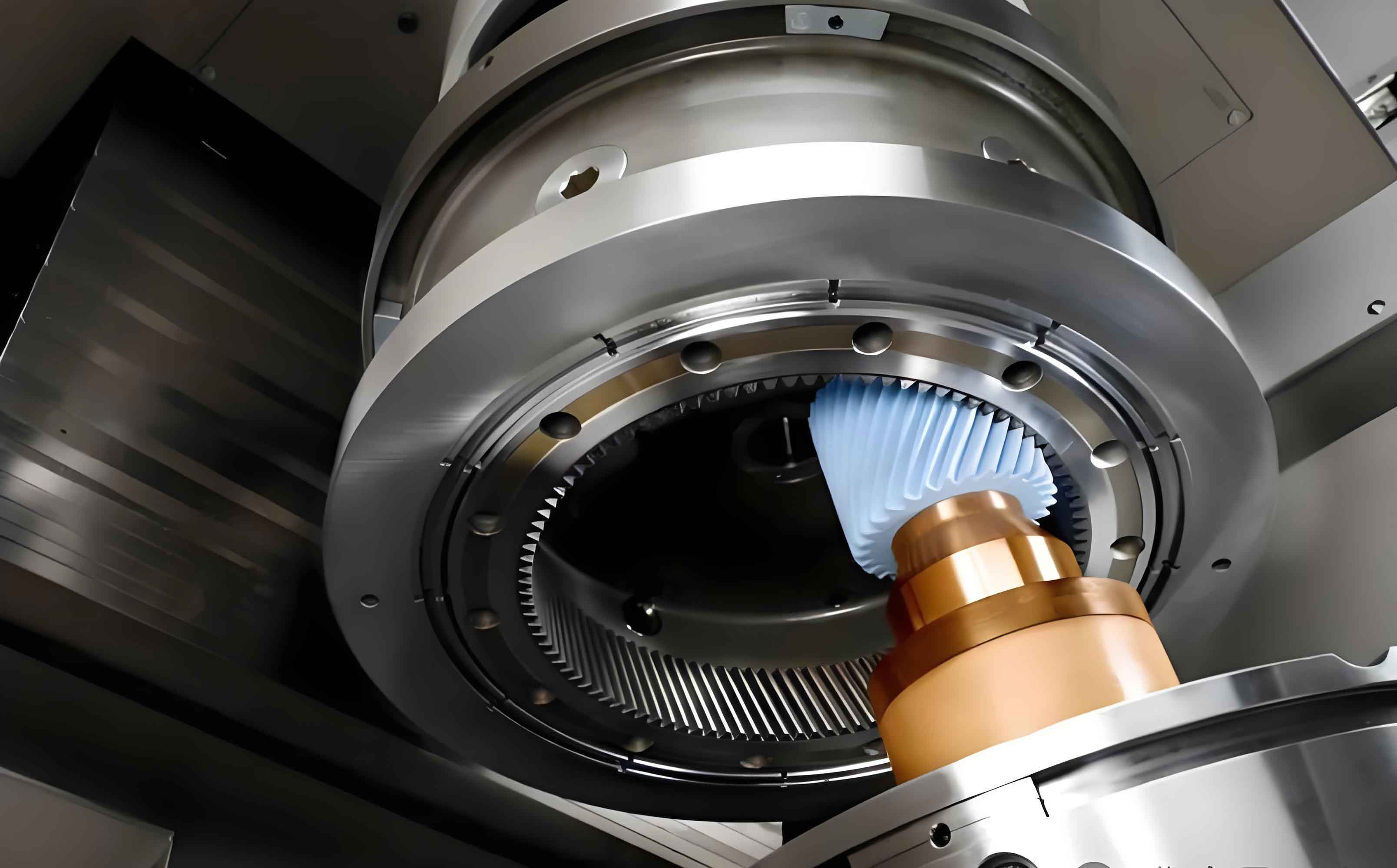
The success of gear honing on an adapted mill hinges on the correct selection of process parameters. Gear honing is an abrasive finishing process typically applied to hardened gears using a helical honing wheel impregnated with abrasive grains. The crossed-axes configuration generates a relative sliding motion along the tooth flanks, gently removing material and correcting errors.
Key Parameters for Gear Honing:
- Honing Wheel Speed (Surface Speed): For effective gear honing, the surface speed of the honing wheel is critical. A typical range is 120–150 m/min for steel components. This speed influences the cutting action and surface generation. The required spindle RPM (N) can be calculated from the honing wheel’s pitch diameter (d_h):
$$ N = \frac{1000 \cdot V}{\pi \cdot d_h} $$
where \(V\) is the surface speed in m/min and \(d_h\) is in mm. - Crossed-Axes Angle (Σ): This is the angle between the honing wheel axis and the workpiece gear axis. While a shaving cutter often uses 10°–15°, honing wheels frequently employ a larger angle, sometimes up to 45°, to increase the sliding velocity component, which is beneficial for the abrasive cutting action of gear honing. The optimal angle depends on the module, hardness, and desired finish.
- Axial Feed (Traverse Rate): This is the linear travel of the table per revolution of the workpiece (f_a, in mm/rev). For gear honing, a finer feed is used compared to shaving. Values can range from 0.10 to 0.25 mm/rev for steel, with the lower end promoting a finer finish.
- Radial Infeed: This is the most critical parameter controlling stock removal. The infeed per table stroke (f_r) must be very small to avoid overloading the abrasive grains and causing rapid wear or poor finish. Recommended values are in the range of 0.005 to 0.02 mm per stroke. The total stock removal in gear honing is usually only 0.01–0.05 mm from the tooth flank.
- Honing Pressure/Force: While not directly set on a manual mill, the radial infeed indirectly controls the normal force between the honing wheel and the gear. This force (F_n) relates to the material removal rate (MRR) in gear honing, which can be approximated by:
$$ MRR \propto F_n \cdot V \cdot k $$
where \(k\) is a constant dependent on workpiece material and abrasive characteristics.
The following table summarizes typical parameter ranges for gear honing on adapted equipment:
| Parameter | Symbol | Typical Range for Gear Honing | Notes |
|---|---|---|---|
| Surface Speed | V | 120 – 150 m/min | For hardened steel gears. |
| Crossed-Axes Angle | Σ | 30° – 45° | Larger angles increase sliding action. |
| Axial Feed | f_a | 0.10 – 0.25 mm/rev | Lower feed for finer finish. |
| Radial Infeed per Stroke | f_r | 0.005 – 0.02 mm/stroke | Must be carefully controlled. |
| Total Stock Removal | – | 0.01 – 0.05 mm | Per tooth flank. |
Performance Validation and Case Studies
Extensive practical application has demonstrated that milling machines converted in this manner are fully capable of performing precision gear honing, achieving results comparable to dedicated machines for many applications. The process is particularly effective for finishing hardened gears where the goal is to correct heat treatment distortions, improve surface roughness, and enhance contact patterns without significant stock removal.
For instance, gears with specifications of Module (m) = 4 mm, Number of Teeth (Z) = 50, and Face Width (B) = 40 mm, and another set with m = 3 mm, Z = 50, B = 30 mm, were finished using both horizontal and vertical mill conversions. After honing, the gears were measured for key accuracy parameters. The results, as shown in the table below, confirm that the process consistently achieves quality levels equivalent to AGMA 9 or better, with significant improvements in surface finish and noise characteristics attributable to the effective gear honing action.
| Accuracy Item | AGMA 8 Standard (Typical) | Gear after Honing (m=4, Z=50) Measured Value | Gear after Honing (m=3, Z=50) Measured Value |
|---|---|---|---|
| Radial Composite Error | 0.056 mm | 0.051 mm | 0.049 mm |
| Tooth-to-Tooth Composite Error | 0.036 mm | 0.024 mm | 0.025 mm |
| Profile Error | 0.016 mm | 0.016 mm | 0.019 mm |
| Lead Error | 0.011 mm | 0.015 mm | 0.014 mm |
| Surface Roughness (Ra) | N/A | 0.4 – 0.8 µm | 0.4 – 0.8 µm |
The data clearly indicates that the adapted setup successfully controls critical gear geometry errors. The process of gear honing is exceptionally effective at refining the tooth profile and lead, which are crucial for smooth and quiet operation. The surface roughness achieved is a direct benefit of the abrasive cutting action inherent to gear honing, where the fine grains of the honing wheel polish the tooth flanks to a mirror-like finish.
Advantages, Limitations, and Conclusion
The transformation of standard milling machines into gear honing platforms offers compelling advantages, especially for low-volume production, prototyping, and maintenance operations. The most significant benefit is cost-effectiveness, as it leverages existing capital equipment. The setup is also highly flexible; the attachment can be removed to restore the mill to its original function. It allows for the honing of relatively large-diameter gears that might exceed the capacity of smaller dedicated machines. Furthermore, it provides an excellent hands-on platform for understanding the fundamental kinematics and tribology of the gear honing process.
However, certain limitations exist. The process is generally slower than on a dedicated, fully automated gear honing machine due to manual intervention in feeding and cycle control. Achieving extreme levels of consistency over very large batch sizes might be challenging. The stiffness and damping characteristics of a general-purpose mill may not match those of a machine designed specifically for the dynamic loads of gear honing, potentially limiting the maximum efficient honing pressure or finish quality on very hard materials.
In conclusion, the systematic modification of horizontal and vertical milling machines into capable gear finishing stations is a proven and valuable technique. By focusing on precision in the attachment design, spindle alignment, and feed control, and by meticulously applying the correct parameters for gear honing, it is possible to achieve remarkable finishing results. This approach democratizes access to advanced gear finishing technology, enabling small workshops and R&D departments to perform essential gear honing operations that significantly enhance gear performance, longevity, and acoustic properties. The process of gear honing, with its unique ability to correct hardened gears, finds a practical and accessible implementation route through this innovative adaptation of ubiquitous machine tools.