
The advancement of modern engineering technology imposes increasingly stringent demands on gear transmissions, requiring higher speeds, efficiencies, service life, load capacities, and lower noise levels. This necessitates gear engineers to explore new design and manufacturing processes. In response, we have conducted research into gear honing technology utilizing elastic toroidal honing worms. This article details the underlying mechanisms, distinctive features, the design and manufacturing of the honing worms, the honing apparatus, and preliminary findings regarding the accuracy achievable through this novel gear honing process.
1. Mechanism and Characteristics of Toroidal Honing Worm Gear Honing
Conventional helical gear-type honing theoretically results in point contact. Consequently, the honed tooth surface is formed by the trajectory of this contact point. This method offers very poor corrective capability for tooth profile errors and may even deteriorate the profile, thus demanding high accuracy in the honing tool’s tooth form. While cylindrical worm gear honing provides line contact and a relatively high sliding velocity, its instantaneous contact line forms a very small angle with the direction of relative sliding velocity. Furthermore, the number of teeth in simultaneous contact is low, meaning the honing worm cannot envelop the entire tooth profile of the workpiece at any given instant. In essence, the workpiece’s tooth profile is generated by the nearly vertical motion of the instantaneous contact line along the tooth height, which inherently limits its ability to correct profile errors from prior machining stages.
In contrast, the involute toroidal elastic honing worm—hereafter referred to as the toroidal honing worm—establishes a fundamentally superior contact condition for gear honing. As illustrated in the following figure, the instantaneous contact lines are distributed along the full face width and tooth height. This means that at every moment, the honing worm envelops the complete tooth profile of the workpiece being honed.
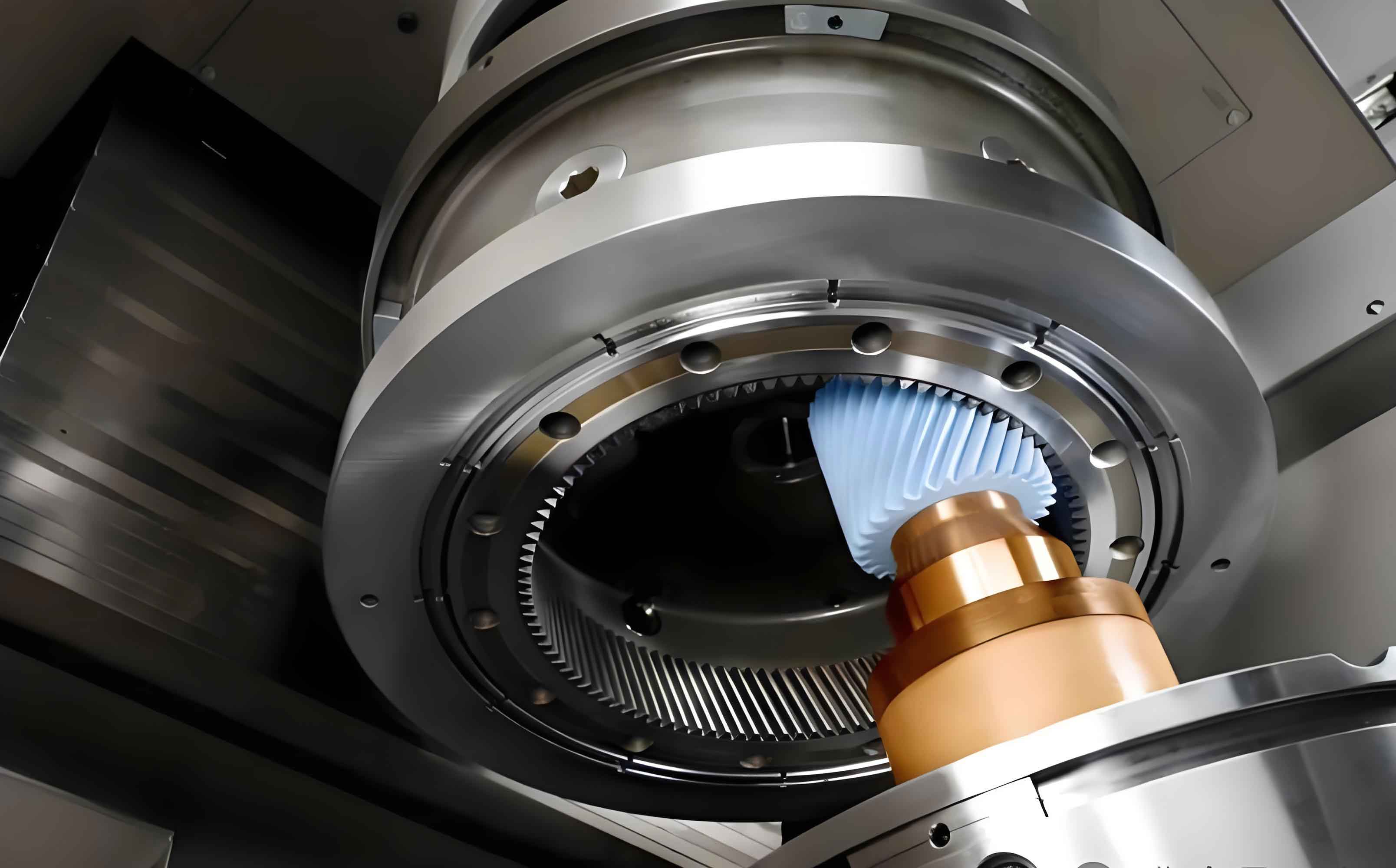
The elastic nature of the honing worm allows for flexible, conformal contact with the workpiece tooth surface. This flexibility, combined with the specific geometry, grants the process excellent abrading and polishing characteristics. It effectively removes microscopic peaks (secondary undulations as shown in schematic diagrams) from the surface, achieving a very high finish. Crucially, due to the line contact geometry, the contact pressure distribution along the tooth height is not uniform when errors are present. Higher pressure is exerted on the peaks of primary profile errors, and lower pressure on the valleys, as conceptually shown in pressure distribution plots. This “high-pressure on high-spots” phenomenon leads to differential removal rates, effectively “cutting the high and filling the low,” thereby enhancing tooth profile accuracy through the gear honing process.
Furthermore, as depicted in related schematics, the number of gear teeth simultaneously in contact with the toroidal honing worm can reach a significant portion of the gear’s total tooth count. This multi-tooth contact not only contributes to improving pitch accuracy but also results in very high production efficiency during the gear honing operation.
Since the kinematic principle of gear honing is fundamentally consistent with that of generating the honing tool itself, the free honing action under conditions of multi-tooth contact allows for a mutual improvement in accuracy between the honing worm and the workpiece. This synergistic effect can relax the required manufacturing precision for the honing worm itself. Additionally, the honing worm does not require re-sharpening, which substantially reduces the overall cost of the gear honing process.
2. Design, Manufacture, and Performance Requirements of the Toroidal Honing Worm
The effectiveness of gear honing with a toroidal worm is closely tied to its design parameters. The following principles must be considered:
- Select an appropriate worm size to meet required honing speed ($v_h$) conditions.
- Choose the number of worm starts ($z_1$) to achieve a suitable lead angle ($\gamma$). When the workpiece is the driving member, the worm’s lead angle must be greater than the friction angle to prevent self-locking. For workpieces with a large helix angle ($\beta$), crossed-axis honing should be considered.
- To allow a single honing worm to hone gears with the same module, pressure angle, and helix angle but different tooth numbers, a “generating gear” or “master gear” concept can be employed for the worm design. The tooth number of this master gear ($z_c$) should be greater than or equal to the maximum number of teeth on the gears to be honed ($z_{2max}$). For multi-start worms, the ratio $z_c / z_1$ should not be an integer.
- After preliminary parameter determination, a theoretical meshing analysis must be performed to verify that the contact lines distribute along the full tooth height and to check for potential undercutting or tooth tip pointing. Original design parameters should be modified if necessary.
For example, given a workpiece gear with: number of teeth $z_2 = 27$, normal module $m_n = 6.5 \text{ mm}$, helix angle $\beta = 8^\circ 6′ 34”$, normal pressure angle $\alpha_n = 20^\circ$, and addendum modification coefficient $x_2 = +0.5$, the detailed design calculations for the corresponding honing worm are summarized in the table below. The geometric meanings of symbols are shown in accompanying diagrams.
| Step No. | Calculation Content | Formula or Selection Method | Example Calculation |
|---|---|---|---|
| 1 | Allowable honing speed $[v_h]$ | Chosen based on honing wheel properties and working conditions. | $[v_h] = 25 \text{ m/s}$ |
| 2 | Honing worm rotational speed $n_1$ (rpm) | Selected based on available equipment and coordinated with $d_1$. | $n_1 = 500 \text{ rpm}$ |
| 3 | Approximate worm pitch diameter $d_1’$ (mm) | $d_1′ = \frac{60000 [v_h]}{\pi n_1}$ | $d_1′ \approx 955 \text{ mm}$ |
| 4 | Lead angle at worm throat $\gamma’$ | For crossed axes: $\gamma’ = \Sigma – \beta$, where $\Sigma$ is the shaft angle. For $z_2$ driving: $\gamma’ > \arctan(\mu)$. |
$\gamma’ = 90^\circ – 8^\circ 6′ 34” = 81^\circ 53′ 26”$ |
| 5 | Number of worm starts $z_1$ | $z_1 = \frac{\pi d_1′ \tan \gamma’}{m_t z_2}$, rounded to integer. $m_t = m_n / \cos \beta$. | $z_1 = 6$ (rounded) |
| 6 | Precise worm pitch diameter $d_1$ (mm) | $d_1 = \frac{m_t z_1}{\tan \gamma’}$ | $d_1 \approx 921.5 \text{ mm}$ |
| 7 | Master gear tooth number $z_c$ | $z_c \ge z_{2max}$, and $z_c / z_1$ not an integer. | $z_c = 30$ |
| 8 | Speed ratio between master gear and worm $i_{c1}$ | $i_{c1} = z_c / z_1$ | $i_{c1} = 5$ |
| 9 | Worm addendum $h_{a1}$ (mm) | $h_{a1} = h_{a2}^* m_n + c^* m_n – (r_{a2} – r_{f2})/2$. $h_{a2}^*$ is gear addendum coeff. | $h_{a1} \approx 9.9 \text{ mm}$ |
| 10 | Worm dedendum $h_{f1}$ (mm) | $h_{f1} = h_{a1} + (r_{a2} – r_{f2})/2$. | $h_{f1} \approx 17.4 \text{ mm}$ |
| 11 | Radius of worm throat arc $R_{a1}$ (mm) | $R_{a1} = \frac{d_1}{2} + h_{a1}$. | $R_{a1} \approx 470.7 \text{ mm}$ |
| 12 | Number of teeth enveloped by worm $z_w$ | $z_w = \frac{z_2}{z_1} \cdot \frac{\theta}{360^\circ}$, $\theta$ is working wrap angle. | With $\theta=110^\circ$, $z_w \approx 1.4$ |
| 13 | Worm length $L$ (mm) | $L \approx d_1 \sin(\theta/2) + 2m_n$. | $L \approx 810 \text{ mm}$ |
2.1 Manufacturing of the Toroidal Honing Worm
The honing worm is fabricated from polyethylene plastic or synthetic rubber mixed with abrasive grains and subsequently foamed. The material must possess good machinability, excellent flexible conformability, and running-in performance. Three primary methods can be employed for generating its tooth profile:
- Form Turning Method: A schematic illustrates the form turning of an involute-generated toroidal worm. The turning tool has a cutting edge profile identical to the transverse tooth profile of the master gear. The worm blank is mounted on the hobber spindle. The tool slide is swiveled to the shaft angle $\Sigma$ (90° for orthogonal axes). The form tool is mounted on a rotary table. After precise adjustment of the center distance $a_{c1}$ and setting the gear ratio $i_{c1}$ via change gears, the tool slide feeds, causing the tool to cut the worm thread from bottom to top.
- Form Grinding Method: The basic setup is similar to the turning method. However, a form grinding wheel replaces the turning tool on the rotary table. The wheel axis is tilted by the clearance angle. The wheel’s working profile is dressed by a diamond point to form the required involute cross-section.
- Approximate Form Grinding Method: This method leverages the excellent running-in property of the honing worm material. It utilizes the workpiece gear itself to perform the final finishing of the worm during the initial gear honing cycles. In this approximate grinding, the wheel and worm undergo no relative feed motion. The wheel’s profile must be specially corrected to account for the interference that would normally be compensated by the differential feed motion in precise generation. Tests show that such an approximate worm profile can achieve ideal meshing conditions after running-in at low speeds.
2.2 Material and Performance Requirements for the Honing Worm
Concurrent with research on the gear honing technique, we have investigated the manufacturing technology and performance metrics for the soft, elastic honing worm. Key performance indicators include:
- Machinability: The material must be amenable not only to turning and grinding but also to achieving the final precise tooth form through running-in during the gear honing process itself.
- Conformability and Elasticity: The worm must possess sufficient elasticity to ensure stable, conformal contact with the workpiece tooth surface under the honing pressure, which is essential for the corrective “averaging” effect in gear honing.
- Abrasive Properties and Wear Resistance: The composite must have appropriate abrasive grain retention, cutting ability, and self-sharpening characteristics to maintain efficient material removal and polishing throughout the gear honing operation. It must also exhibit sufficient wear resistance to ensure consistent performance and tool life.
- Dimensional Stability and Heat Resistance: The material should maintain dimensional stability and not degrade under the frictional heat generated during gear honing.
The synergistic combination of the toroidal geometry and the elastic, abrasive-composite material is what enables the superior performance of this gear honing method.
3. Preliminary Experimental Study on the Honing Device and Honing Accuracy
To understand the performance of the honing worm and the accuracy attainable through gear honing, we have conducted preliminary tests on seven types of gears. Two were single helical gears specifically made for testing (e.g., $m_n=6.5 \text{ mm}$, $z_2=27$, carburized and hardened, pre-honed by hobbing). The other five were double-helical gears for a high-speed wire rod mill main reducer (e.g., $\beta \approx 8^\circ$, $m_n=6.5 \text{ mm}$, $z_2=27, 77$, ion-nitrided, pre-finished by precision hobbing, accuracy requirement Grade 6, surface finish requirement $\nabla 7$).
The experiments demonstrate that gear honing with a toroidal worm can efficiently enhance surface finish. Each honing pass can improve the finish by 2-3 grades. For instance, on a large $m_n=10 \text{ mm}$ herringbone gear with an initial finish of $\nabla 5$, the finish reached $\nabla 8$ after two honing passes with a total machining time of 60 minutes. Tests also indicate that the toroidal honing worm is capable of achieving ultra-high finishes up to $\nabla 10$ during gear honing. Notably, for the same level of measured roughness, a honed surface is superior to one produced by other mechanical finishing methods because the microscopic peaks are honed flat, resulting in better wear resistance, anti-scuffing capability, and oil film formation ability.
The beneficial effect of toroidal worm gear honing on improving geometric accuracy has been preliminarily confirmed. The following results were obtained under basic test conditions without special precision-enhancing measures, after just one honing pass.
The table below summarizes typical improvements observed in key gear accuracy parameters after gear honing.
| Gear Parameter | Typical Pre-Honing Error | Typical Post-Honing Error | Primary Improvement Mechanism in Honing |
|---|---|---|---|
| Tooth Profile Error (Primary Undulation) | Significant mid-profile concavity (~40 μm total) | Profile noticeably leveled; error reduced by ~30-50% | Elastic averaging & differential pressure from line contact along height |
| Tooth Profile Error (Secondary Undulation/Roughness) | Microscopic peaks and valleys | Amplitude reduced by ~40-60% | Abrasive polishing action of elastic composite |
| Tooth Direction (Lead) Error | Observable deviation across face width | Error reduced and profile smoothed | Multi-tooth contact averaging along face width |
| Surface Finish $R_a$ | e.g., 1.6-3.2 μm ($\nabla 5$) | e.g., 0.4-0.8 μm ($\nabla 7-\nabla 8$) | Abrasive cutting/polishing at high sliding velocity |
Graphical results from a single tooth flank further illustrate these effects. A plot of tooth lead error before and after honing shows a clear reduction in deviation and a smoother trace. Similarly, an overlaid plot of tooth profile error (pre-honing magnified 200x, post-honing 500x) for two teeth demonstrates the dramatic leveling of a pre-existing ~40 μm mid-profile concavity after gear honing. The amplitude of the microscopic secondary undulation is also nearly halved.
The theoretical advantages—elastic averaging, multi-tooth contact, and full-tooth-height line contact—are thus validated by these initial measurements. The corrective action of the gear honing process is evident not only in roughness reduction but also in the mitigation of certain systematic profile and lead errors.
4. Conclusion
Our research on gear honing technology employing elastic toroidal honing worms, though still in preliminary stages, has proven its significant potential. This process offers distinct advantages: the equipment is relatively simple, operation is straightforward, and it can dramatically improve gear tooth surface finish. Its inherent corrective capabilities, derived from the unique contact mechanics between the elastic toroidal worm and the gear, show promise for enhancing overall gear accuracy in a highly efficient manner. By potentially relaxing the required precision of the honing tool and eliminating the need for re-sharpening, this gear honing method presents a prospect for reducing manufacturing costs. The combination of high efficiency, excellent surface quality generation, and accuracy improvement makes toroidal worm gear honing a technology with broad application prospects in the field of high-quality gear finishing.