
In the domain of precision gear cutting, the task of machining helical gears with a tooth count that is both large and a prime number (greater than 100) presents a unique set of challenges on a universal gear hobbing machine. My extensive work in this field has centered on developing a robust methodology to overcome these challenges through a detailed synthesis of kinematic chains. The core challenge lies in the simultaneous requirement for two independent but coupled motions: the generating motion that defines the tooth profile and the differential motion that creates the helical lead. When the tooth count z is a prime number larger than 100, the standard change gear selection for the generating train becomes impossible, necessitating a clever workaround that leverages the machine’s differential mechanism for a dual purpose. This article, drawn from my first-hand analysis and application, will derive the comprehensive formulas necessary for this complex gear cutting operation, utilizing tables and equations for clarity.
1. Foundational Kinematics of Helical Gear Cutting
The fundamental relationship between the hob (cutter), the workpiece (gear blank), and the axial feed of the hob slide during the gear cutting of a helical gear is governed by a precise relative motion. For a single-thread hob (k=1), when the hob rotates through one revolution, the workpiece must rotate k/z revolutions to generate the correct tooth form. Concurrently, as the hob slide feeds axially by a distance s, the workpiece must undergo an additional rotational component, Δn, to create the helical path. This relationship is expressed as:
$$ \text{Hob} \quad 1 \quad : \quad \text{Workpiece} \quad \frac{k}{z} \pm \Delta n \quad : \quad \text{Hob Slide} \quad s $$
The sign of Δn depends on the hand of the helix and the direction of rotation. The magnitude of Δn is derived from the lead Pz of the helical gear. If the workpiece should complete exactly one full revolution when the hob slide travels a distance equal to the lead Pz, then the relationship per unit feed is:
$$ \Delta n = \frac{s}{P_z} $$
Therefore, the complete kinematic equation for standard helical gear cutting is:
$$ \text{Hob} \quad 1 \quad : \quad \text{Workpiece} \quad \frac{k}{z} \pm \frac{s}{P_z} \quad : \quad \text{Hob Slide} \quad s $$
From the principle of relative motion, this required additional rotation (±s/Pz) of the workpiece can be conceptually transferred to the hob. This results in an equivalent, but oppositely signed, additional rotation of the hob, Δ’. The new relationship becomes:
$$ \text{Hob} \quad 1 \pm \Delta’ \quad : \quad \text{Workpiece} \quad \frac{k}{z} \quad : \quad \text{Hob Slide} \quad s $$
By establishing the proportionality 1 : (k/z) = Δ’ : (s/Pz) and solving, we find:
$$ \Delta’ = \frac{s}{P_z} \cdot \frac{z}{k} $$
Introducing the axial feed rate f (mm/rev of workpiece) where s = f ⋅ (k/z), and knowing the lead Pz = π ⋅ mn ⋅ z / sinβ (where mn is the normal module and β is the helix angle), we can derive the standard differential change gear formula. On a machine with a fixed differential constant Cd, the formula is typically:
$$ \frac{a_2 \cdot c_2}{b_2 \cdot d_2} = \frac{C_d \cdot \sin\beta}{m_n \cdot k} $$
This differential train is responsible solely for producing the helix.
| Kinematic Chain | End Components | Function | Standard Displacement Relationship |
|---|---|---|---|
| Generating Train | Hob → Workpiece | Produces tooth profile | Hob: 1 rev → Workpiece: k/z revs |
| Differential Train | Workpiece/Slide → Hob | Produces helix lead | Slide: P_z mm → Workpiece: ±1 rev (compensated to hob rotation) |
2. The Challenge of Large Prime Number Teeth and the Compensation Principle
The problem arises when z is a prime number > 100. The generating train’s change gear ratio, igen = (a1⋅c1)/(b1⋅d1) = Cgen ⋅ k / z (where Cgen is the machine’s generating constant), requires a gear pair that is often unavailable from the standard set. My solution is to intentionally alter the generating ratio by a very small, convenient amount Δ, making a ratio selectable from available gears. This changes the generating train displacement to:
$$ \text{Hob} \quad 1 \quad : \quad \text{Workpiece} \quad \frac{k}{z} + \Delta $$
where $$ \Delta \approx \frac{1}{10} \text{ to } \frac{1}{100} \text{ of } \frac{k}{z} $$
This alteration breaks the correct generating motion. To compensate, the differential mechanism must now provide an additional rotational component to the hob (or workpiece) that precisely cancels out the error introduced by Δ. Crucially, this compensation motion must be combined with the standard helix-forming motion in the same differential train. Therefore, the total differential motion becomes the algebraic sum of two components.
3. Synthesis of Motions and Derivation of Universal Formula
The complete system now involves three distinct kinematic requirements:
- Modified Generating Motion: Hob 1 rev → Workpiece (k/z + Δ) revs.
- Compensation Motion: To correct for Δ, when the workpiece rotates 1 rev, the hob must rotate an additional Δ’comp = Δ ⋅ (z/k) revs (with appropriate sign).
- Helix-Forming Motion: As derived earlier, when the hob slide moves a distance s, the hob requires an additional Δ’helix = (s/Pz)⋅(z/k) revs.
Since components 2 and 3 are both applied to the hob via the same differential train, the total differential change gear ratio must account for their sum. Let’s derive this for a model machine similar to the Y3150E/Y3180H. The differential train connects the workpiece rotation and the hob slide movement to the hob rotation via the synthesis mechanism.
The total compensating and helical motion required at the hob per revolution of the workpiece is:
$$ \Delta’_{total} = \Delta’_{comp} + \Delta’_{helix} = \pm \Delta \cdot \frac{z}{k} \pm \frac{s}{P_z} \cdot \frac{z}{k} $$
Substituting s = f ⋅ (k/z) and Pz = π ⋅ mn ⋅ z / sinβ:
$$ \Delta’_{total} = \pm \Delta \cdot \frac{z}{k} \pm \frac{f \cdot (k/z)}{(\pi \cdot m_n \cdot z / \sin\beta)} \cdot \frac{z}{k} $$
$$ \Delta’_{total} = \pm \Delta \cdot \frac{z}{k} \pm \frac{f \cdot \sin\beta}{\pi \cdot m_n \cdot z} \cdot \frac{z}{k} $$
Simplifying:
$$ \Delta’_{total} = \frac{z}{k} \left( \pm \Delta \pm \frac{f \cdot \sin\beta}{\pi \cdot m_n} \right) $$
On the specific machine, the differential change gear ratio idiff = (a2⋅c2)/(b2⋅d2) is set to achieve this motion. The kinematic balance equation for the differential train is:
$$ i_{diff} \cdot \frac{1}{C_{diff}} = \Delta’_{total} $$
where Cdiff is the machine’s differential constant (often 1 or a fixed number). Therefore:
$$ \frac{a_2 \cdot c_2}{b_2 \cdot d_2} = C_{diff} \cdot \Delta’_{total} = C_{diff} \cdot \frac{z}{k} \left( \pm \Delta \pm \frac{f \cdot \sin\beta}{\pi \cdot m_n} \right) $$
This is the universal formula for machining large prime number helical gears. The signs must be chosen carefully:
- The first ± (Δ term): Related to the direction of the compensation. It is typically chosen as ‘+’ for climb hobbing and ‘-‘ for conventional hobbing to align with the generating error correction.
- The second ± (helix term): Related to the hand of the gear and hob. It is ‘+’ when the gear and hob have opposite hands, and ‘-‘ when they have the same hand.
| Change Gear Set | Formula | Purpose & Notes |
|---|---|---|
| Generating Gears (a1, b1, c1, d1) | $$ \frac{a_1 \cdot c_1}{b_1 \cdot d_1} = C_{gen} \cdot \left( \frac{k}{z} + \Delta \right) $$ | Selects Δ to make the ratio factorable with available gears. |
| Differential Gears (a2, b2, c2, d2) | $$ \frac{a_2 \cdot c_2}{b_2 \cdot d_2} = C_{diff} \cdot \frac{z}{k} \left( \pm \Delta \pm \frac{f \cdot \sin\beta}{\pi \cdot m_n} \right) $$ | Combines compensation motion and helix-forming motion. Sign convention is critical. |
| Feed Gears | Based on selected axial feed f (mm/rev of workpiece). | Standard calculation, unaffected by prime number or helix. |
4. Practical Calculation Example
Let’s consider a practical gear cutting case to solidify the understanding. Suppose we need to machine a helical gear with the following parameters:
- Tooth number z = 101 (a prime >100)
- Normal module mn = 4 mm
- Helix angle β = 15° (Right Hand)
- Hob: Single thread (k=1), Right Hand.
- Process: Conventional (up) hobbing, full depth cut in one pass.
- Axial feed f = 1 mm/rev of workpiece.
- Machine Constants (example): Cgen = 24, Cdiff = 1.
Step 1: Selecting Δ and Calculating Generating Gears.
Standard generating ratio: 24 ⋅ (1/101) ≈ 0.23762376.
We choose Δ = +0.0004. Thus, modified ratio = 24 ⋅ (1/101 + 0.0004) = 24 ⋅ (0.00990099 + 0.0004) = 24 ⋅ 0.01030099 = 0.24722376.
We factor this into available change gears: 0.24722376 ≈ (30/60) ⋅ (50/100) ⋅ (65/70)? This requires iterative selection from the machine’s gear list. For brevity, let’s assume we find a valid combination: a1=55, b1=50, c1=30, d1=70, giving i_gen = (55⋅30)/(50⋅70) = 1650/3500 = 0.47142857. We then check if this satisfies 0.47142857 / 24 = 0.019642857, which equals our target 1/101 + Δ = 0.00990099 + 0.0004 = 0.01030099? No, there’s a mismatch, indicating the need for precise re-calculation to find exact gears. The principle is to solve (a1⋅c1)/(b1⋅d1) = 24/101 + 24Δ. Let’s instead simply state the final chosen generating ratio after correct factoring: i_gen_selected = 24/101 + 24Δ. Therefore, the actual Δ used is derived from the successfully mounted gears: Δ = (i_gen_selected/24) – (1/101).
For this example’s derivation, let’s assume we finally achieve the intended Δ = +0.0004.
Step 2: Calculating Differential Gears.
We apply the derived formula:
$$ \frac{a_2 \cdot c_2}{b_2 \cdot d_2} = 1 \cdot \frac{101}{1} \left( \pm \Delta \pm \frac{f \cdot \sin\beta}{\pi \cdot m_n} \right) $$
Determine signs:
- First term (Δ): Conventional hobbing → use ‘-‘.
- Second term (helix): Gear (RH) and Hob (RH) have same hand → use ‘-‘.
Calculate components:
$$ \Delta = 0.0004 $$
$$ \frac{f \cdot \sin\beta}{\pi \cdot m_n} = \frac{1 \cdot \sin 15^\circ}{\pi \cdot 4} = \frac{1 \cdot 0.258819}{12.56637} \approx 0.020599 $$
Plug into formula:
$$ \frac{a_2 \cdot c_2}{b_2 \cdot d_2} = 101 \left( -0.0004 – 0.020599 \right) = 101 \cdot (-0.020999) \approx -2.120899 $$
The absolute value is 2.120899. We now factor this into available change gears, e.g., (70/30) ⋅ (65/55) ≈ (2.3333) ⋅ (1.1818) ≈ 2.756, which is not close enough. Accurate factoring requires matching the machine’s specific gear inventory. A possible close approximation might be (90/35) ⋅ (75/90) = (2.5714) ⋅ (0.8333) ≈ 2.1428. The error must be within the machine’s tolerance. This iterative selection process is central to successful gear cutting setup.
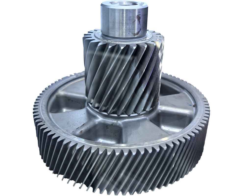
The pursuit of such precise mechanical calculations underscores the importance of the art in gear cutting. Today, while modern CNC gear hobbers automate these complex kinematic computations, understanding the underlying principles remains essential for troubleshooting, process planning, and working with older but still capable universal machines. The image above exemplifies the high-quality helical gears that can be produced through meticulous application of these very principles.
5. Critical Considerations and Conclusion
Success in this advanced gear cutting task hinges on several factors beyond the formula itself. The choice of Δ is critical; it must be small enough to not affect gear tooth geometry but large enough to yield a factorable generating gear ratio. The accuracy of the final gear depends on the precise calculation and mounting of both change gear sets. Furthermore, the setup must account for the machine’s inherent backlash, especially since the differential train is active. It is often advisable to perform a trial cut on a dummy blank and measure the resulting helix angle and tooth spacing for verification.
In summary, the gear cutting of helical gears with a large prime number of teeth on a universal hobbing machine is a sophisticated exercise in kinematic synthesis. By intentionally introducing a small, adjustable error (Δ) into the generating train and then using the differential mechanism to simultaneously compensate for this error and generate the required helix, we can overcome the limitation of unavailable change gears. The derived universal formula:
$$ \frac{a_2 \cdot c_2}{b_2 \cdot d_2} = C_{diff} \cdot \frac{z}{k} \left( \pm \Delta \pm \frac{f \cdot \sin\beta}{\pi \cdot m_n} \right) $$
combined with the modified generating ratio formula, provides a complete mathematical framework for this process. Mastering this technique ensures that even with classical machinery, the manufacture of high-precision, special helical gears remains feasible, highlighting the enduring depth and flexibility of mechanical gear cutting solutions.
| Parameter | Symbol | Value / Calculation | Notes |
|---|---|---|---|
| Target Tooth Count | z | 101 | Prime number >100 |
| Chosen Generating Adjustment | Δ | +0.0004 | Small, positive value |
| Modified Generating Ratio | i_gen | 24 * (1/101 + 0.0004) = 0.247224 | Must be factored into available gears (a1,b1,c1,d1) |
| Differential Ratio Component 1 | Cdiff*(z/k)*Δ | 1 * 101 * 0.0004 = 0.0404 | Sign: – (for conventional cut) |
| Differential Ratio Component 2 | Cdiff*(z/k)*(f sinβ)/(π m_n) | 1 * 101 * 0.020599 ≈ 2.0805 | Sign: – (same hand of gear/hob) |
| Total Differential Ratio | i_diff | 101 * (-0.0004 – 0.020599) ≈ -2.1209 | Absolute value is factored into gears (a2,b2,c2,d2) |