
In the realm of modern gear manufacturing, the face hobbing method for spiral bevel and hypoid gears has gained significant traction due to its high efficiency in mass production. This gear cutting process involves continuous indexing and simultaneous machining of both tooth flanks, making it a preferred choice for automotive and aerospace applications. However, the complexity of controlling tooth contact characteristics, such as contact pattern and transmission error, poses a challenge. This article delves into the fundamental principles of gear cutting via face hobbing, detailing the calculation of machine settings and proposing a novel method for contact characteristics control. Through mathematical derivations, parametric analysis, and experimental validation, I aim to provide a comprehensive guide for optimizing gear cutting processes.
The formation of tooth surfaces in face hobbing is rooted in the generating principle, where a simulated crown gear, or generating gear, interacts with the workpiece. The gear cutting process utilizes a cutter head with multiple blades that rotate and move relative to the gear blank, creating the desired tooth geometry. In this method, both convex and concave flanks are machined simultaneously, which necessitates precise control over the gear cutting parameters to ensure proper meshing. The basic kinematic model involves a generating gear that conjugates with the pinion and gear separately, using an indirect generation approach. This allows for the creation of gear teeth with uniform depth, but it can lead to edge contact under manufacturing errors. To mitigate this, local contact conditions are introduced by tilting the cutter axis, transforming the generating surface from a plane to a cone. This modification breaks the line contact into point contact at the design reference point, enhancing the gear’s performance under load.
The mathematical foundation for gear cutting in face hobbing begins with defining coordinate systems. Let me establish a static machine coordinate system $\Sigma = \{O; \mathbf{i}, \mathbf{j}, \mathbf{k}\}$, where $O$ is the cradle center, $\mathbf{i}$ and $\mathbf{j}$ span the cradle plane, and $\mathbf{k}$ is the cradle axis. The generating gear coordinate system is $\Sigma_p = \{O_p; \mathbf{i}_p, \mathbf{j}_p, \mathbf{k}_p\}$, and the cutter coordinate systems are $\Sigma_c = \{O_c; \mathbf{i}_c, \mathbf{j}_c, \mathbf{k}_c\}$ and $\Sigma_{c1} = \{O_{c1}; \mathbf{i}_{c1}, \mathbf{j}_{c1}, \mathbf{k}_{c1}\}$. The blade geometry is described in $\Sigma_o = \{O_o; \mathbf{i}_o, \mathbf{j}_o, \mathbf{k}_o\}$, where $O_o$ coincides with $O_c$, and $\mathbf{k}_o$ is the cutter axis. The tilt angle $I_1$ and blade curvature are key parameters in gear cutting that influence the tooth surface curvature.
The position vector of any point on the blade, for instance on the concave flank (outer blade), in $\Sigma_o$ is given by:
$$\mathbf{R}_o^{(ob)} = \mathbf{M}(\mathbf{k}_o, \theta) \left( \mathbf{R}_o^{(op)} + \mathbf{R}_o^{(ps)} + \mathbf{R}_o^{(sb)} \right)$$
where:
$$\mathbf{R}_o^{(op)} = [0, r_o, 0]^T$$
$$\mathbf{R}_o^{(ps)} = \mathbf{M}(\mathbf{k}_o, \delta_{01}) [0, \Delta r_c, 0]^T$$
$$\mathbf{R}_o^{(sb)} = \mathbf{M}(\mathbf{k}_o, \delta_{01}) \mathbf{M}(\mathbf{i}_o, \theta_{bt}) [0, -t_{cb}, s_c t_{cb}]^T$$
Here, $r_o$ is the nominal cutter radius, $\Delta r_c$ is the outer blade radius correction, $\delta_{01}$ is the blade direction angle, $\theta_{bt}$ is the central angle on the blade, $t_{cb} = 2 k_{cr} \sin(\theta_{bt}/2)$ with $k_{cr}$ as the blade curvature radius, and $s_c = \pm 1$ for convex or concave blades. The rotation angle $\theta$ represents the cutter rotation. After applying tilt, the vector is transformed to the generating gear system:
$$\mathbf{R}_p^{(bc)} = \mathbf{V}_{qt}^{(p)} + S_1 \mathbf{M}(\mathbf{k}_p, \pi + \beta_{10}) \mathbf{R}_o^{(ob)} + h_{x1} \mathbf{k}_p$$
where $S_1$ is the radial distance, $\beta_{10}$ is the generating gear spiral angle, and $h_{x1}$ is the axial shift. The generating gear tooth surface is then formed as the envelope of the blade trajectory:
$$\mathbf{R}_p^{(ac)} = \mathbf{M}(\mathbf{k}_p, \varphi) \mathbf{R}_p^{(bc)}$$
with $\varphi = (z_c / z_0) \theta$, where $z_c$ is the number of blade groups and $z_0$ is the generating gear tooth number. The normal vector is derived from partial derivatives:
$$\mathbf{n}_c^{(p)} = \frac{\partial \mathbf{R}_p^{(ac)}}{\partial \theta} \times \frac{\partial \mathbf{R}_p^{(ac)}}{\partial \varphi}$$
Transforming to the gear coordinate system yields the gear tooth surface point and normal vector. This gear cutting process ensures that both flanks are generated simultaneously, but control over contact characteristics requires further refinement.
To achieve local contact and control the contact pattern, I propose a method that allows arbitrary specification of contact reference points on the tooth surface and simultaneous control of both flanks. The process begins with determining the basic gear parameters and generating gear geometry. Based on the generating principle, the gear tooth surface equations are derived. Initially, without modification, the gear pair exhibits line contact. To induce local contact, a contact reference point is designated on the gear’s axial section. Its position parameters $(r_c, l_c)$ define the radial and longitudinal coordinates. The gear cutting parameters are then adjusted to ensure meshing at this point under given assembly conditions.
The contact pattern morphology is controlled by specifying parameters such as contact ellipse length factor, diagonal direction, and transmission error amplitude. Using local synthesis theory, the required curvature parameters at the contact reference point on the pinion are calculated. The relationship between relative curvature and contact characteristics is expressed through equations derived from differential geometry. For instance, the contact ellipse length $l_c$ is related to the relative curvatures:
$$l_c = 2 \sqrt{\frac{0.0254 \Delta K_{\text{min}}}{2}}$$
where $\Delta K_{\text{min}}$ is the minimum relative normal curvature. The transmission error is influenced by the relative motion acceleration, which depends on the curvature parameters. By solving nonlinear equations, the gear cutting parameters, including tilt angles and blade curvatures, are optimized to meet the desired contact characteristics.
The influence of control parameters on contact characteristics is critical in gear cutting. Let me analyze the effects using a case study of a hypoid gear pair with a 10-tooth pinion and a 41-tooth gear. The basic parameters are summarized in Table 1.
| Parameter | Pinion | Gear |
|---|---|---|
| Number of teeth | 10 | 41 |
| Module (mm) | 5.4388 | – |
| Shaft angle (°) | 90 | – |
| Offset (mm) | 20 | – |
| Spiral angle (°) | 50 | 37.13 |
| Face width (mm) | 31.67 | 30 |
| Hand of spiral | Left | Right |
| Pressure angle sum (°) | 40 | – |
Three groups of control parameters are tested to evaluate their impact, as shown in Table 2.
| Control Parameter | Group 1 | Group 2 | Group 3 |
|---|---|---|---|
| Gear tilt angle (°) | 0.5 | 2 | 5 |
| Pinion tilt angle (°) | 2 | 5 | 10 |
| Generating gear tooth number correction | -0.025 | 0 | 0.025 |
| Gear outer blade curvature | -5e-4 | 0 | -5e-4 |
| Gear inner blade curvature | -5e-4 | 0 | |
| Pinion outer blade curvature | -3.571e-4 | 0 | 1e-3 |
| Pinion inner blade curvature | -3.571e-4 | 0 | 1e-3 |
The analysis reveals that tilt angles significantly affect the contact ellipse length and transmission error amplitude. As tilt angles increase, the contact ellipse shortens, and transmission error rises. The gear tilt angle also influences the diagonal direction more than the pinion tilt angle. Blade curvatures primarily modify the diagonal direction and transmission error. Positive curvature increases both, while negative curvature decreases them. The generating gear tooth number correction shifts the zero-transmission-error point along the tooth profile but has minimal effect on contact pattern morphology. This interdependence implies that in gear cutting, selecting contact parameters requires trade-offs; for example, a shorter contact length and larger diagonal direction necessitate a larger transmission error amplitude.
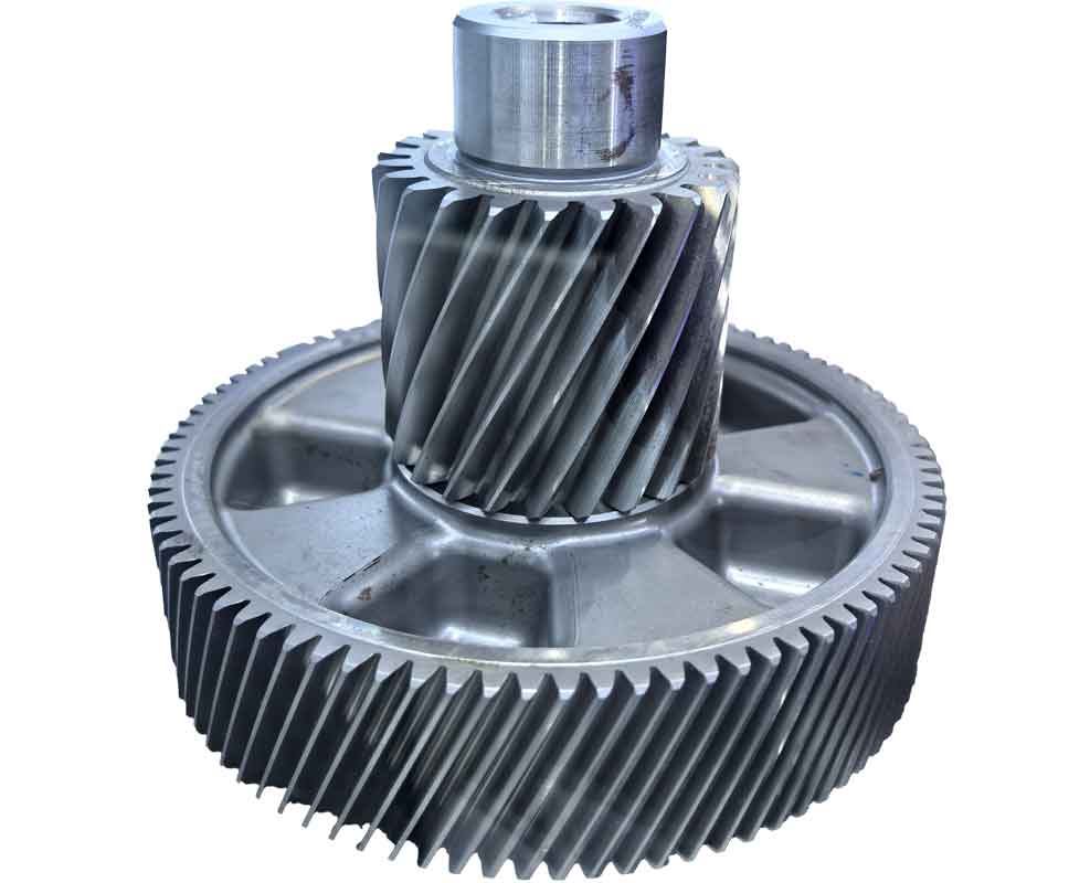
To validate the gear cutting method and contact control algorithm, I conducted a numerical example and a physical machining test. For the gear pair in Table 1, the contact reference point on the gear convex flank was set at 10% from the toe at the mid-face width, and on the concave flank at the center. After optimization, the control parameters were determined, as listed in Table 3.
| Control Variable | Optimized Value | Contact Characteristic | Achieved Value |
|---|---|---|---|
| Gear tilt angle (°) | 0.874 | Length factor (concave) | 0.304 |
| Pinion tilt angle (°) | 5.131 | Length factor (convex) | 0.297 |
| Gear concave blade curvature | 2.874e-4 | Diagonal direction (concave) (°) | 50.00 |
| Gear convex blade curvature | 2.236e-4 | Diagonal direction (convex) (°) | 50.00 |
| Pinion concave blade curvature | 5.596e-5 | Transmission error (concave) (“) | 16.17 |
| Pinion convex blade curvature | -2.049e-4 | Transmission error (convex) (“) | 14.54 |
The corresponding machine settings for gear cutting are provided in Table 4.
| Parameter | Pinion | Gear |
|---|---|---|
| Root angle (°) | 14.645 | 71.666 |
| Horizontal offset (mm) | -0.2397 | -1.3790 |
| Vertical offset (mm) | 30.122 | -2.161 |
| Axial offset (mm) | -2.563 | 1.038 |
| Radial distance (mm) | 96.240 | 96.151 |
| Ratio of roll | 4.182132 | 1.02003 |
| Tilt angle (°) | 5.131 | 0.874 |
| Swivel angle (°) | 5.082 | 6.629 |
| Number of blade groups | 13 | 13 |
| Outer blade diameter (mm) | 88.725 | 87.332 |
| Outer blade pressure angle (°) | 20.930 | 22.792 |
| Outer blade offset angle (°) | 14.261 | 14.255 |
| Inner blade diameter (mm) | 87.272 | 88.670 |
| Inner blade pressure angle (°) | 18.948 | 17.212 |
| Inner blade offset angle (°) | 14.261 | 14.255 |
The theoretical contact patterns showed good alignment with the specified parameters. The gear cutting was performed on a CNC hypoid generator, and the gear teeth were measured using a gear measuring center. The tooth deviation was less than 17.3 μm, with the contact area deviations under 10 μm, confirming the accuracy of the gear cutting process. A rolling test on a gear testing machine demonstrated that the actual contact patterns matched the theoretical predictions, validating the effectiveness of the contact control method in gear cutting.
In conclusion, this article has presented a detailed methodology for gear cutting in face hobbing hypoid gears, focusing on machine setting calculation and contact characteristics control. The proposed method enables arbitrary positioning of contact reference points and simultaneous control of both tooth flanks, which is essential for high-performance gear applications. Through parametric analysis, I have shown that tilt angles and blade curvatures are key factors in governing contact pattern morphology, with inherent trade-offs between parameters. The gear cutting algorithm was verified via numerical simulations and physical machining tests, demonstrating its practical applicability. This work contributes to advancing gear cutting technologies, offering a systematic approach for optimizing hypoid gear manufacturing.