
In the field of precision gear manufacturing for robotics and automation, RV reducers play a critical role due to their high torque capacity and compact design. As a key component, the planetary gear within an RV reducer must exhibit exceptional positional accuracy between its internal and external teeth, as this directly influences transmission error, load distribution, wear, noise, and overall lifespan. Throughout my extensive involvement in gear production, I have observed that achieving such precision is a significant challenge, given the multi-step manufacturing process and stringent tolerances. Among various machining methods, gear hobbing has emerged as a preferred technique for planetary gear external teeth, balancing high efficiency with acceptable accuracy. This article delves into two common anomalies encountered during planetary gear hobbing—large angular phase fluctuation and severe eccentricity between internal and external teeth—and presents practical solutions based on theoretical analysis and process validation. By sharing these insights, I aim to contribute to the advancement of gear hobbing practices in the industry.
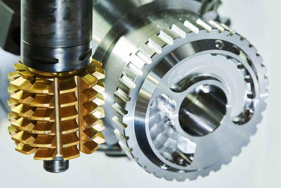
The gear hobbing process for planetary gears involves using a hob to generate the external tooth profile through a continuous indexing motion. Compared to gear grinding, gear hobbing offers higher production rates, making it suitable for mass production. However, maintaining precise angular relationships and concentricity between internal and external teeth is paramount. In our facility, we utilize high-precision hobbing machines equipped with FANUC systems, which include gear-tooth searching functions to align the hob with the gear blank. Despite these capabilities, anomalies can arise, necessitating a deep understanding of the underlying causes and corrective measures.
Angular Phase Fluctuation Between Internal and External Teeth
During the gear hobbing of planetary gears, one of the most frequent issues is the excessive variation in the angular phase, denoted as α, which is the angle between the midpoint of an internal tooth space and the midpoint of an external tooth, measured from the gear center. In our trials, we recorded angular phase fluctuations up to ±0.1°, far exceeding the tolerance limits and resulting in low yield rates. This anomaly directly impacts the meshing performance of the RV reducer, leading to increased vibration and noise.
Upon investigation, we identified two primary causes for this angular phase instability. First, insufficient hobbing allowance on the semi-finished external teeth of the planetary gear can lead to non-uniform material removal. When compensating the machine’s C-axis rotation angle to adjust the angular phase, one flank of the external teeth may remain uncut, causing deviations from the theoretical position and thus phase errors. Second, the gear-tooth search function, while intended to reference the hob position relative to the gear blank, can introduce errors due to variations in the semi-finished gear quality. Each search cycle may yield slightly different alignment, leading to inconsistent phase outcomes when batch processing.
To address these issues, we implemented a comprehensive solution. The hobbing allowance was increased to ensure adequate material removal on both flanks. Based on measurements, we determined that a single-side allowance of approximately 0.3 mm is optimal, compared to the previous 0.05 mm. This adjustment eliminated the non-cutting phenomenon and provided more room for phase correction. Additionally, we modified the gear hobbing procedure by disabling the continuous search function after the first piece. For the initial gear, we run the search program, measure the angular phase, and compensate the C-axis accordingly. The compensation value is often converted to a chordal length for practical adjustment, derived from the following relationship for the external tooth pitch circle radius:
$$ r’ = r \cdot \frac{a’}{a} $$
where $r$ is the reference pitch radius calculated as $r = \frac{m \cdot z}{2}$, with $m$ being the module and $z$ the number of teeth. $a’$ is the actual center distance during gear hobbing, and $a$ is the theoretical center distance. The chordal compensation value $C$ is then given by:
$$ C = 2r’ \sin\left(\frac{\Delta \theta}{2}\right) $$
where $\Delta \theta$ is the angular compensation in radians. This approach minimizes search-induced errors and stabilizes the angular phase across batches. The table below summarizes the causes and solutions for angular phase fluctuation:
| Cause | Solution | Impact |
|---|---|---|
| Insufficient hobbing allowance | Increase single-side allowance to ~0.3 mm | Ensures complete cutting of both tooth flanks |
| Errors from continuous gear-tooth search | Disable search after first piece; use C-axis compensation | Reduces alignment variability |
| Variations in semi-finished gear quality | Implement strict control on pre-hobbing dimensions | Improves consistency in gear hobbing |
Through these measures, we successfully reduced the angular phase variation to within ±0.02°, significantly enhancing the qualification rate. This highlights the importance of precise allowance management and process control in gear hobbing operations.
Eccentricity Between Internal and External Teeth
Another critical anomaly in planetary gear hobbing is excessive eccentricity between the internal and external teeth, quantified as radial runout (Fr). In our measurements, Fr values ranged from 0.05 mm to 0.08 mm, failing to meet the required gear accuracy grades. Such eccentricity can cause uneven load distribution and accelerated wear in RV reducers, compromising their reliability.
Our analysis began with verifying the hobbing machine’s condition. We checked the runout and flatness of the machine base and pressure head, confirming that both were within 0.005 mm, indicating minimal machine-related contributions. Next, we examined the hobbing fixture, which initially used a cylindrical spline to engage with the internal teeth of the planetary gear. By measuring the base pitch dimensions, specifically the common normal length (Wk), we discovered a significant fit clearance between the internal teeth and the cylindrical spline. The common normal length for standard spur gears is calculated as:
$$ W_k = m \cos \alpha \left[ \pi (k – 0.5) + z \cdot \text{inv} \alpha \right] $$
where $\alpha$ is the pressure angle, $k$ is the number of teeth spanned given by $k = \frac{\alpha}{180^\circ} z + 0.5$ (with $\alpha$ in degrees), and $\text{inv} \alpha = \tan \alpha – \alpha$ (in radians). The larger Wk value for the internal teeth compared to the spline indicated a loose fit, allowing the gear to shift during gear hobbing and causing eccentricity.
To resolve this, we replaced the cylindrical spline fixture with a tapered spline fixture. The tapered design allows for a tighter fit across variations in internal tooth dimensions, as there is always a cross-section along the taper that matches the gear’s internal teeth closely. This eliminates clearance without the need for frequent fixture changes. Additionally, we enforced strict geometrical tolerances on the planetary gear blank, including flatness and parallelism of the end faces within 0.005 mm, and perpendicularity of the internal teeth to the end faces within 0.01 mm. These measures prevent tilting during gear hobbing and ensure uniform tooth thickness along the face width. The following table outlines the key steps taken:
| Aspect | Improvement | Result |
|---|---|---|
| Fixture design | Switch from cylindrical to tapered spline fixture | Eliminates fit clearance; improves positioning |
| Gear blank tolerances | Control end face parallelism and internal tooth perpendicularity | Prevents misalignment during gear hobbing |
| Process calibration | Regularly check fixture runout and flatness | Ensures machine stability |
After implementation, the radial runout (Fr) was reduced to below 0.02 mm, meeting the precision requirements. This demonstrates how fixture optimization and dimensional control are vital for minimizing eccentricity in gear hobbing processes.
Process Characteristics and Advantages of Gear Hobbing
Based on our experience, the gear hobbing process for planetary gears involves several control points to ensure success. First, the semi-finished gear must have adequate external tooth allowance, typically around 0.3 mm per side, to accommodate phase adjustments. Second, geometrical accuracies such as end face parallelism and internal tooth perpendicularity must be tightly managed. Third, the use of a tapered spline fixture is recommended to secure the gear blank without play. Fourth, machine calibration, including checking the runout of the fixture base and pressure head, should be performed regularly. Finally, in the gear hobbing sequence, the gear-tooth search function should be used only for the first piece, with subsequent pieces processed without search to avoid alignment inconsistencies.
The advantages of gear hobbing over alternative methods are substantial. Compared to generating gear grinding, which requires frequent wheel dressing and is slower, gear hobbing offers higher efficiency without sacrificing accuracy. Form grinding, while precise, has even lower productivity due to larger contact areas and the need for customized wheels. Wire cutting has been attempted for planetary gears, but it often results in poor surface finish, affecting reducer performance and noise levels. In contrast, gear hobbing is versatile, capable of producing straight, helical, and herringbone gears, as well as splines with special profiles using tailored hobs. Its broad applicability, combined with high precision and stability, makes gear hobbing a preferred choice for both R&D and batch production. The table below compares different planetary gear machining methods:
| Method | Accuracy | Efficiency | Flexibility | Surface Finish |
|---|---|---|---|---|
| Gear Hobbing | High (can approach grinding) | High | High (various gear types) | Good |
| Generating Grinding | Very High | Low (due to wheel dressing) | Moderate | Excellent |
| Form Grinding | High | Very Low | Low (wheel-specific) | Excellent |
| Wire Cutting | Moderate | Low | High (complex shapes) | Poor |
Moreover, gear hobbing benefits from continuous technological advancements, such as improved machine rigidity and CNC controls, which enhance its capability to meet the demanding tolerances of RV reducer gears. In our production line, we have integrated these optimizations, resulting in a stable and reliable gear hobbing process that consistently yields high-quality planetary gears.
Conclusion
In summary, gear hobbing is a critical technology for manufacturing planetary gears in RV reducers, offering a balance of precision and productivity. Through systematic analysis, we have addressed two major anomalies—angular phase fluctuation and eccentricity—by adjusting hobbing allowances, optimizing fixtures, and refining process controls. The solutions presented, such as using tapered spline fixtures and disabling continuous search functions, have proven effective in reducing variations and improving yield rates. As gear hobbing continues to evolve with better machines and techniques, it remains a cornerstone in gear manufacturing. However, practitioners must remain vigilant, as other factors like material properties and tool wear can also influence outcomes. By sharing these findings, I hope to foster further innovation and collaboration in the field, ultimately advancing the reliability and performance of RV reducers through superior gear hobbing practices.
Looking ahead, ongoing research into tool geometry, cutting parameters, and real-time monitoring during gear hobbing will likely unlock even higher levels of accuracy. For instance, adaptive control systems that dynamically adjust feeds and speeds based on sensor feedback could minimize anomalies. Additionally, the integration of AI for predictive maintenance of hobs and fixtures may further enhance process stability. In our ongoing work, we are exploring these avenues to push the boundaries of what gear hobbing can achieve for complex components like planetary gears. The journey toward perfecting gear hobbing is continuous, but with each improvement, we move closer to ideal gear performance in critical applications.