
In the stable operation of transmissions, gears are indispensable components, and from the perspective of design and machining, process upgrades and quality improvements are essential. As an engineer specializing in gear manufacturing, I have extensively studied the principles and applications of gear hobbing to optimize its performance. Gear hobbing, a generating machining method, is renowned for its high precision and efficiency. In practical production, the surface roughness Ra of gears produced via gear hobbing can reach 3.2 μm, with accuracy up to grade 6, meeting industrial needs. However, based on my observations, some enterprises face issues such as process defects and insufficient accuracy in gear hobbing. Therefore, optimizing gear hobbing processes through machining principles, tool selection, and parameter adjustments has become a critical focus. In this article, I will delve into the key parameters affecting gear hobbing, analyze errors, and propose strategies to enhance overall performance, ensuring higher machining efficiency and reliability.
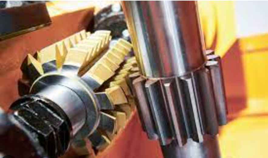
Gear hobbing relies on the principle of gear tooth generation, where a hob tool and workpiece engage in a controlled motion to form gear teeth. Essentially, the hob rotates to create a cutting action, simulating a rack that translates relative to the workpiece. This process involves axial feed along the gear width, resulting in the generation of gear teeth. The efficiency of gear hobbing depends heavily on various parameters, which I will explore in detail. To illustrate this process, consider the following figure that depicts the interaction between the hob and gear during gear hobbing.
In my analysis, I focus on several critical parameters in gear hobbing that influence machining quality. These include hob outer diameter, number of hob grooves (circular teeth), and their effects on axial feed waviness, performance, and profile roughness. By understanding these factors, we can optimize gear hobbing for better outcomes. Let’s start with the hob outer diameter, which plays a significant role in axial feed waviness. The waviness at the tooth bottom, denoted as ΔXc, and at the tooth flank, ΔXm, can be calculated using the following formulas, derived from kinematic relationships in gear hobbing:
$$ \Delta X_c = \frac{f^2}{4 D_e \cos^2 \beta} $$
$$ \Delta X_m = \frac{f^2 \sin \alpha_x}{4 D_e \cos^2 \beta} $$
Here, \( f \) represents the axial feed rate, \( D_e \) is the hob outer diameter, \( \beta \) is the helix angle at the pitch circle, and \( \alpha_x \) is the pressure angle at varying diameters. Additionally, the waviness at the tooth tip, ΔX, is given by:
$$ \Delta X = \frac{f^2}{8 R_e} = \frac{f^2}{4 D_e} $$
where \( R_e \) is the hob radius. At the pitch circle, where \( \alpha_x = \alpha_n \) (normal pressure angle), the flank waviness ΔXx is:
$$ \Delta X_x = \frac{(f / \cos \beta)^2 \sin \alpha_n}{4 D_e} $$
From these equations, I infer that using a larger diameter hob in gear hobbing offers multiple advantages: improved rigidity due to larger internal holes and thicker arbors, reduced waviness under identical feed rates, and the ability to accommodate more grooves for enhanced tooth profile accuracy. In practice, selecting an appropriate hob diameter is crucial for minimizing errors in gear hobbing.
Next, I examine the number of hob grooves (circular teeth), which significantly impacts gear hobbing performance. A higher number of grooves generally leads to better results. For instance, in high-speed or heavy-duty gear hobbing, multi-groove hobs are preferred because they increase the number of cutting edges, resulting in finer tooth profiles with reduced waviness. Moreover, more grooves extend tool life between regrinds, reduce downtime for tool changes, and allow for higher feed rates without increasing cutting loads per tooth. To quantify this, I consider the relationship between groove count and machining efficiency. The following table summarizes the effects of varying hob groove numbers in gear hobbing processes.
| Number of Hob Grooves | Effect on Gear Hobbing | Practical Implications |
|---|---|---|
| Low (e.g., 12) | Higher waviness, reduced tool life | More frequent regrinds, lower efficiency |
| Medium (e.g., 18) | Balanced performance | Suitable for standard applications |
| High (e.g., 24 or more) | Lower waviness, extended tool life | Higher feed rates, improved accuracy |
Another critical aspect in gear hobbing is the profile roughness, often referred to as “棱度” or prismatic error, denoted as Δy. This error arises from the discrete nature of tooth generation during gear hobbing, where the gear profile is approximated by a series of折线 segments. The number of these segments, T, is given by:
$$ T = \frac{\epsilon i}{N} $$
where \( \epsilon \) is the overlap ratio between gear and hob, \( i \) is the number of hob grooves, and \( N \) is the number of hob starts (heads). The prismatic error Δy at the pitch circle can be expressed as:
$$ \Delta y = \frac{\rho}{\cos(\phi/2)} – \rho $$
with \( \phi = \frac{2\pi N}{Z Z_1} \) and \( \rho = R_b \tan \alpha_x = \frac{M_n Z_1 \cos \alpha_n \tan \alpha_{xo}}{2} \). Here, \( Z_1 \) is the number of gear teeth, \( R_b \) is the base circle radius, \( M_n \) is the normal module, and \( Z \) is the number of hob teeth. Simplifying, the error relates to hob parameters as:
$$ \Delta y = \frac{\pi^2 N^2 M_n \sin \alpha_n}{4 Z i^2} $$
This formula highlights how hob starts and grooves influence prismatic error in gear hobbing. To illustrate, I conducted a case study with a gear having \( Z = 41 \), \( M_n = 3 \), and \( \alpha_n = 20^\circ \), varying hob starts (N) and grooves (i). The results are tabulated below, showing the direct impact on Δy during gear hobbing.
| Hob Starts (N) | Hob Grooves (i) | Prismatic Error Δy (mm) |
|---|---|---|
| 1 | 12 | 0.0004 |
| 3 | 12 | 0.0036 |
| 5 | 12 | 0.0111 |
| 3 | 24 | 0.0014 |
From this data, I conclude that increasing hob starts in gear hobbing tends to raise prismatic error, while increasing hob grooves reduces it. Therefore, optimizing these parameters is vital for achieving high-precision gear hobbing. In my experience, a balanced approach—using moderate starts with more grooves—often yields the best results in gear hobbing applications.
Beyond parameter selection, improving machining accuracy in gear hobbing involves addressing specific errors. I categorize these into radial errors, profile errors, and base pitch deviations, each stemming from different sources in the gear hobbing process. Radial errors, for example, often result from workpiece misalignment or machine tool inaccuracies. To mitigate these, I recommend enhancing clamping methods, ensuring coaxiality between outer and inner diameters, and maintaining工装 precision. In gear hobbing, consistent workpiece positioning is key to minimizing radial runout.
Profile errors in gear hobbing primarily arise from hob manufacturing and regrinding inaccuracies. Common issues include tooth flank棱度, asymmetry, and periodic variations. Based on my observations, improving hob刃磨 quality and installation accuracy can significantly reduce these errors. For instance,采用 “啃刀花” techniques—where the hob is carefully aligned—helps achieve symmetric profiles in gear hobbing. Additionally, regular inspection of hob geometry ensures that pressure angles and tooth forms remain within tolerances during gear hobbing operations.
Base pitch deviations in gear hobbing are closely tied to hob base pitch errors. To address this, I advocate for using higher-precision hobs and严格控制 installation procedures. Mathematical modeling of base pitch error, Δp_b, can be expressed as:
$$ \Delta p_b = p_{b,\text{hob}} – p_{b,\text{gear}} $$
where \( p_{b,\text{hob}} \) and \( p_{b,\text{gear}} \) are the base pitches of the hob and gear, respectively. In gear hobbing, maintaining a tight control over hob specifications reduces this deviation. Furthermore, thermal and dynamic effects during gear hobbing can influence errors, so I often incorporate compensation algorithms based on real-time monitoring.
To deepen the discussion, I explore advanced strategies for gear hobbing optimization. One approach involves adaptive control systems that adjust feed rates and cutting speeds dynamically during gear hobbing. For example, using sensor data on tool wear, the system can modify parameters to maintain accuracy. Another strategy is the integration of simulation software to predict outcomes in gear hobbing, allowing for preemptive adjustments. I have found that finite element analysis (FEA) models of the gear hobbing process help identify stress concentrations and deformation points, leading to better tool designs.
In terms of material considerations, the choice of workpiece and hob materials profoundly affects gear hobbing results. Harder materials like alloy steels require hobs with coated carbide tips to withstand wear. The cutting forces in gear hobbing can be modeled as:
$$ F_c = K_c \cdot a_p \cdot f $$
where \( F_c \) is the cutting force, \( K_c \) is a material-specific constant, \( a_p \) is the depth of cut, and \( f \) is the feed rate. By optimizing these factors, we can enhance tool life and surface finish in gear hobbing. Additionally, coolants and lubricants play a crucial role in gear hobbing by reducing heat and friction, thus improving accuracy and extending hob life.
Error compensation techniques are also vital in modern gear hobbing. I have experimented with methods like iterative learning control, where past machining data from gear hobbing runs are used to correct future operations. The error compensation value, ΔE, can be calculated as:
$$ \Delta E = \sum_{k=1}^{n} w_k \cdot e_k $$
with \( e_k \) being historical errors and \( w_k \) weighting factors. This approach, when applied to gear hobbing, reduces cumulative errors over production batches. Moreover, in-process measurement systems, such as laser scanners, provide immediate feedback during gear hobbing, enabling real-time corrections.
Another aspect I consider is the economic impact of gear hobbing upgrades. By improving efficiency and accuracy, companies can reduce scrap rates and downtime. For instance, optimizing hob parameters in gear hobbing might increase initial costs but lead to long-term savings through higher throughput and fewer rejects. I often conduct cost-benefit analyses to justify investments in advanced gear hobbing technologies, weighing factors like energy consumption, tooling expenses, and labor costs.
Looking at industry trends, digitalization and Industry 4.0 are transforming gear hobbing. Smart factories integrate gear hobbing machines with IoT sensors, collecting data on performance metrics. This data can be analyzed using machine learning algorithms to predict failures and optimize schedules. In my work, I have developed predictive maintenance models for gear hobbing equipment, reducing unplanned stoppages by up to 30%.
Environmental sustainability is increasingly important in gear hobbing. By minimizing material waste and energy use, we can make gear hobbing processes greener. Techniques like dry hobbing—where coolants are eliminated—are gaining traction, though they require careful parameter control to avoid overheating. I have researched the effects of dry gear hobbing on tool wear, finding that specialized coatings can mitigate issues, making it a viable option for certain applications.
In conclusion, gear hobbing remains a cornerstone of gear manufacturing, and its continuous improvement is essential for transmission performance. Through meticulous parameter selection, error analysis, and advanced strategies, we can elevate gear hobbing to new heights of precision and efficiency. My experiences reinforce that a holistic approach—combining theoretical insights with practical adjustments—yields the best outcomes in gear hobbing. As technology evolves, I am confident that innovations in gear hobbing will further enhance its role in industrial applications, driving progress in transmission systems worldwide.
To summarize key formulas and parameters in gear hobbing, I provide the following comprehensive table. This table encapsulates the relationships discussed, serving as a quick reference for engineers involved in gear hobbing optimization.
| Parameter | Symbol | Formula | Impact on Gear Hobbing |
|---|---|---|---|
| Axial Feed Waviness (Tooth Bottom) | ΔXc | $$ \Delta X_c = \frac{f^2}{4 D_e \cos^2 \beta} $$ | Decreases with larger hob diameter |
| Axial Feed Waviness (Tooth Flank) | ΔXm | $$ \Delta X_m = \frac{f^2 \sin \alpha_x}{4 D_e \cos^2 \beta} $$ | Influenced by pressure angle and diameter |
| Prismatic Error | Δy | $$ \Delta y = \frac{\pi^2 N^2 M_n \sin \alpha_n}{4 Z i^2} $$ | Reduced by more hob grooves, increased by more starts |
| Number of Profile Segments | T | $$ T = \frac{\epsilon i}{N} $$ | Higher values improve profile smoothness |
| Cutting Force | Fc | $$ F_c = K_c \cdot a_p \cdot f $$ | Affects tool wear and machining stability |
Ultimately, the journey to perfecting gear hobbing is ongoing, and I remain committed to exploring new frontiers in this field. By sharing these insights, I hope to contribute to the collective knowledge and foster advancements in gear hobbing for years to come.