
In high-precision gear manufacturing for automotive transmissions, such as Dual-Clutch Transmissions (DCT), the final gear geometry is paramount. A persistent challenge encountered in our production involved the consistent upper deviation of the tip relief value (fKo) on ground gears. The measurement report graphs revealed a distinctive signature: the tip relief curve ascended smoothly but made an abrupt, near-horizontal turn just before the evaluation boundary. This horizontal segment was identified as the profile of the tip chamfer. Since a portion of this chamfer contour fell below the tip relief evaluation boundary line, it was incorrectly included in the relief evaluation zone. The fitting algorithm, in determining the straight line that best approximates the relief zone, was influenced by this horizontal segment, causing the fitted line to tilt. The evaluated tip relief value is the horizontal distance between the endpoints of this fitted line; a tilted line directly results in a larger measured horizontal distance, explaining the systematic upper deviation.
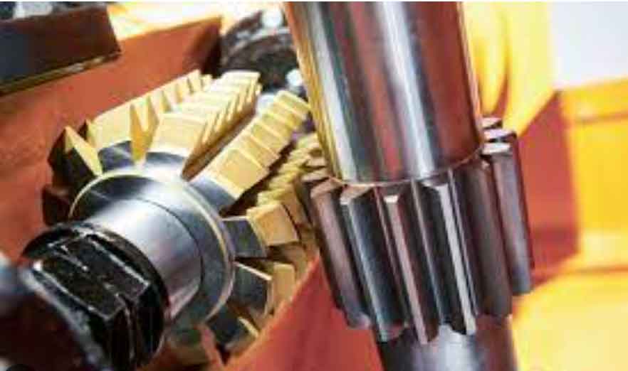
This problem necessitates an analysis of the geometric relationship between the roughing and finishing operations. Typically, the tip chamfer, which does not participate in gear meshing under load, is generated during the initial roughing stage—gear hobbing. In contrast, the tip relief, which is functional under loaded conditions and requires high accuracy, is meticulously generated during the final finishing operations like gear grinding or honing. Therefore, the root cause and solution must be investigated within the interplay between the gear hobbing and gear grinding processes.
The principles of generating gear cutting dictate that the hob’s parameters are decisive for the tooth form features produced on the workpiece. For a given hob (disregarding wear), if the tooth thickness of the machined gear is held constant, the relative position of all form features on the tooth flank is fixed and unadjustable via process parameters. The only way to shift these features parallel to themselves relative to the gear axis is by altering the workpiece’s tooth thickness. In essence, the hob “imprints” its profile onto the gear blank at a depth determined by the hob-workpiece center distance, which directly controls tooth thickness.
Tool designers anticipate potential mismatches between the gear hobbing and grinding stages. Consider the extreme scenario where the hobbed gear is at the minimum tooth thickness (hobbing at maximum material removal) and the same gear is ground to the maximum allowable tooth thickness (grinding at minimum material removal). In this case, during gear hobbing, the hob is closer to the workpiece center, causing all generated form features, including the start point of the tip chamfer, to be located at a smaller diameter. Subsequently, during grinding, minimal stock is removed, offering little corrective action on these pre-machined features. The net effect can be a final tip chamfer start diameter smaller than the design minimum, causing its contour to intrude into the relief evaluation zone. Even without such extremes, cumulative errors from hob manufacturing, machine tool inaccuracies, measurement variances, and heat treatment distortion can lead to the same outcome: a hobbed chamfer start point that is too low for the subsequent grinding process to correct within the allowable tooth thickness tolerance.
While the fundamental solution lies in modifying the hob design, this approach is often impractical due to the tool’s complexity, high cost, and long lead time. A more economical and immediate strategy is to adjust the gear hobbing process parameters to utilize the existing hob effectively. The core of this strategy is the application of profile shift, or “modification,” during the gear hobbing operation.
Analysis of Profile Shift in Gear Hobbing and Its Impact on Ground Tip Relief
In generating cutting, when the reference line of the cutting tool (e.g., the hob’s pitch line) is tangent to the gear’s pitch circle, a standard gear is produced. If the tool is deliberately shifted radially away from or towards the workpiece, a profile-shifted gear is generated. Crucially, the same hob can produce both standard and shifted gears. The profile shift changes the working engagement depth but does not alter the fundamental geometry defined by the hob, such as the base circle and module. A positive profile shift (tool moved away from the workpiece) increases the tip and root circle diameters, while a negative shift decreases them.
This characteristic is key to our problem. By applying a positive profile shift during gear hobbing, we can radially “lift” the entire tooth profile generated by the hob, including the start point of the tip chamfer. The magnitude of this radial movement for any feature on the tooth flank is equal to the profile shift amount, \( x \cdot m_n \), where \( x \) is the profile shift coefficient and \( m_n \) is the normal module.
| Aspect | Problem State | Solution via Gear Hobbing |
|---|---|---|
| Core Issue | Tip chamfer contour interferes with tip relief evaluation after grinding. | Adjust the radial position of the hobbed chamfer start point. |
| Root Cause | Hobbed chamfer start diameter is too small relative to the final ground profile. | Apply a positive profile shift during the gear hobbing operation. |
| Mechanism | The grinding process cannot sufficiently “correct” the low chamfer start within part tolerances. | Positively shifting the hob radially outward increases the tip circle and all related feature diameters. |
| Control Parameter | Direct measurement of chamfer start point is difficult in production. | Control is achieved indirectly via a precise tooth thickness measurement (e.g., span measurement or pin diameter). |
| Goal | Ensure the chamfer profile lies completely outside the tip relief evaluation zone after grinding. | Calculate the required profile shift \(\Delta x\) to achieve the necessary radial increase \(\Delta r\). |
To implement this, we need to translate the required radial adjustment of the chamfer into a quantifiable change in a shop-floor measurable parameter: tooth thickness. A common and precise method for controlling tooth thickness is the measurement over pins (or balls), denoted as \( M \). We must establish the relationship between the profile shift coefficient \( x \) and the measurement over pins \( M \).
For a helical gear, the general formula for the measurement over pins \( M \) is:
For an even number of teeth:
$$ M = \frac{m_n z \cos \alpha_t}{\cos \beta \cos \alpha_M} + d_p $$
For an odd number of teeth:
$$ M = \frac{m_n z \cos \alpha_t}{\cos \beta \cos \alpha_M} \cos\left(\frac{90^\circ}{z}\right) + d_p $$
where:
\( m_n \) = Normal module
\( z \) = Number of teeth
\( \alpha_t \) = Transverse pressure angle, \( \tan \alpha_t = \frac{\tan \alpha_n}{\cos \beta} \)
\( \beta \) = Helix angle
\( d_p \) = Pin diameter
\( \alpha_M \) = Pressure angle at the pin center
The key lies in calculating \( \alpha_M \), which is derived from the basic geometry of the involute. The involute function \( \text{inv}(\alpha) = \tan \alpha – \alpha \) (in radians). The relationship is given by:
$$ \text{inv}(\alpha_M) = \frac{d_p}{d_b} + \frac{s}{d} + \text{inv}(\alpha_t) – \frac{\pi}{z} $$
where \( d_b \) is the base diameter and \( s \) is the transverse circular tooth thickness on the pitch circle. This can be expanded and expressed in terms of the profile shift coefficient \( x \):
$$ \text{inv}(\alpha_M) = \frac{d_p}{m_n z \cos \alpha_n} + \frac{2x \tan \alpha_n}{z} + \text{inv}(\alpha_t) – \frac{\pi}{2z} $$
This final equation explicitly links the profile shift coefficient \( x \) to \( \alpha_M \), which in turn is used in the formula for \( M \). Therefore, for a desired change in \( x \), we can calculate the corresponding new \( \alpha_M \), and subsequently the new target value for the measurement over pins \( M \).
Practical Application and Calculation Example
Consider a gear with the following parameters, representative of the initial problem:
- Normal Module, \( m_n = 2.25 \, \text{mm} \)
- Number of Teeth, \( z = 29 \)
- Normal Pressure Angle, \( \alpha_n = 19^\circ \)
- Helix Angle, \( \beta = 25^\circ \)
- Initial Profile Shift Coefficient, \( x_{\text{initial}} = +0.015 \)
- Pin Diameter, \( d_p = 5.0 \, \text{mm} \)
- Stock Allowance for Grinding (per flank), \( A = 0.08 \, \text{mm} \)
Step 1: Determine Required Radial Shift.
From the measurement graph analysis, to move the chamfer start point completely outside the evaluation zone, its radius needed to increase by approximately \( \Delta r = 0.05 \, \text{mm} \). The required additional positive profile shift during gear hobbing is therefore:
$$ \Delta x = \frac{\Delta r}{m_n} = \frac{0.05}{2.25} \approx 0.02222 $$
Thus, the new target profile shift coefficient is:
$$ x_{\text{new}} = x_{\text{initial}} + \Delta x = 0.015 + 0.02222 = 0.03722 $$
Step 2: Calculate Corresponding Change in Measurement Over Pins (M).
First, calculate the transverse pressure angle:
$$ \alpha_t = \arctan\left(\frac{\tan \alpha_n}{\cos \beta}\right) = \arctan\left(\frac{\tan 19^\circ}{\cos 25^\circ}\right) \approx 20.646^\circ $$
The base diameter is:
$$ d_b = m_n z \cos \alpha_t / \cos \beta \approx 2.25 \times 29 \times \cos 20.646^\circ / \cos 25^\circ \approx 62.971 \, \text{mm} $$
The transverse tooth thickness on the pitch circle for the initial design is:
$$ s_t = m_n (\pi/2 + 2 x_{\text{initial}} \tan \alpha_n) / \cos \beta \approx 2.25 \times (\pi/2 + 2 \times 0.015 \times \tan 19^\circ) / \cos 25^\circ \approx 3.904 \, \text{mm} $$
Using the formula for \( \text{inv}(\alpha_M) \) with \( x_{\text{initial}} = 0.015 \):
$$ \text{inv}(\alpha_{M,\text{initial}}) = \frac{5.0}{62.971} + \frac{2 \times 0.015 \times \tan 19^\circ}{29} + \text{inv}(20.646^\circ) – \frac{\pi}{2 \times 29} $$
Solving this (noting \( \text{inv}(20.646^\circ) \approx 0.01626 \)) gives \( \alpha_{M,\text{initial}} \approx 23.512^\circ \).
For an odd number of teeth (z=29), the initial measurement over pins is:
$$ M_{\text{initial}} = \frac{62.971}{\cos 23.512^\circ} \times \cos\left(\frac{90^\circ}{29}\right) + 5.0 \approx 81.609 \, \text{mm} $$
Now, repeat the calculation for \( x_{\text{new}} = 0.03722 \):
$$ \text{inv}(\alpha_{M,\text{new}}) = \frac{5.0}{62.971} + \frac{2 \times 0.03722 \times \tan 19^\circ}{29} + 0.01626 – \frac{\pi}{58} $$
This yields \( \alpha_{M,\text{new}} \approx 23.601^\circ \).
The new target measurement over pins is:
$$ M_{\text{new}} = \frac{62.971}{\cos 23.601^\circ} \times \cos\left(\frac{90^\circ}{29}\right) + 5.0 \approx 81.682 \, \text{mm} $$
Step 3: Determine Process Adjustment.
The required change in the hobbed gear’s tooth thickness, as reflected in the M value, is:
$$ \Delta M = M_{\text{new}} – M_{\text{initial}} \approx 81.682 – 81.609 = 0.073 \, \text{mm} $$
It is critical to remember that this \( M_{\text{new}} \) is the target value after grinding. Therefore, the gear hobbing operation must produce a hobbed gear with a larger tooth thickness to provide the necessary stock. The hobbed tooth thickness target must be increased by twice the stock allowance per flank (\(2A\)) in the relevant dimension. For span measurement, the adjustment is direct. For the M value, the hobbed target becomes approximately \( M_{\text{hob}} = M_{\text{new}} + 2A \cdot \text{(factor relating tooth thickness change to M change)} \). Precise calculation of this offset is essential.
Implementing this positive shift adjustment in the gear hobbing process directly addressed the issue. Subsequent measurement reports for the ground gears showed compliant tip relief graphs and values, with the chamfer profile clearly outside the evaluation boundary. This method allowed for the continued use of the existing hobs, yielding significant economic benefits.
Conclusion and Key Considerations
The strategy of applying a calculated positive profile shift during the gear hobbing operation provides an effective and efficient solution to correct tip relief measurement errors caused by interfering tip chamfers in ground gears. This approach leverages the fundamental geometric relationship between the roughing and finishing stages.
When applying this method, several critical points must be observed:
- Approximation Nature: The calculation method for helical gears using transverse section formulas is standard industry practice but remains an approximation. The discrepancy grows with increasing helix angle. The method is generally reliable for helix angles below \(45^\circ\). For higher angles, more sophisticated 3D geometric modeling is recommended.
- Accounting for Finishing Stock: The calculated target dimensions (like \(M_{\text{new}}\)) are for the finished ground part. The gear hobbing parameters must be set to produce a larger tooth thickness to accommodate the precise stock removal during grinding. Failure to include this offset will result in under-sized final parts.
- Holistic Gear Geometry Check: The profile shift adjustment does not only affect the tip diameter and chamfer. It also modifies the root diameter and the position of other critical form points (e.g., the start of active profile, or T.I.F. point). Any shift must be verified against all other gear drawing tolerances to ensure no new non-conformities are introduced. The new hobbed root diameter, for instance, must still allow for sufficient grinding stock without creating an under-cut condition.
- Process Control: After determining the new theoretical hob center distance or measurement value, rigorous process capability studies should be conducted to ensure the adjusted gear hobbing process remains stable and produces consistent results within the tighter implied tolerances.
In summary, strategic adjustment of the gear hobbing process via profile shift is a powerful tool for solving specific interface problems in multi-stage gear manufacturing. It underscores the importance of viewing the entire manufacturing chain as a connected system, where a calculated modification in an early, more flexible stage like gear hobbing can reliably resolve precision issues in a final, less adjustable operation like gear grinding.