
In precision manufacturing, gear shaping is a critical process for producing internal gears, splines, and other complex components, particularly in industries such as wind energy where large-tooth-width gears with widths exceeding 300 mm and high accuracy (e.g., Grade 7 or above per national standards) are required. The hydrostatic spindle in gear shaping machines plays a pivotal role in ensuring machining accuracy, as it provides high rotational precision and oil film stiffness. However, challenges arise due to heat generation from reciprocating motion and periodic lateral forces from the connecting rod, which can degrade the stiffness of the hydrostatic oil film and compromise gear shaping quality. This study addresses the insufficient stiffness of the hydrostatic spindle in a large-tooth-width, long-stroke gear shaping machine, specifically the YKW51160 model, by proposing structural optimization designs. Through fluid-structure interaction (FSI) analysis, we enhance the bearing capacity and oil film stiffness, ensuring reliable performance under dynamic loads during gear shaping operations.
The hydrostatic bearing in gear shaping spindles typically features four oil chambers with capillary restrictors, where pressurized oil forms a thin film between the spindle and bearing to support radial loads. Under ideal conditions, the oil film thickness is uniform, but external forces—such as those from the connecting rod in gear shaping mechanisms—cause eccentricities, altering chamber pressures and reducing stiffness. To mitigate this, we explore two optimization schemes: chamfering the edges of the oil chambers and redesigning the chambers into a rectangular-ambulatory-plane (referred to as “回字形” in the original context) configuration. These modifications aim to increase the effective load-bearing area and improve flow stability, thereby boosting performance in gear shaping applications. This paper details the finite element modeling of the oil film, FSI-based validation, and empirical verification, highlighting significant improvements in bearing capacity and stiffness.
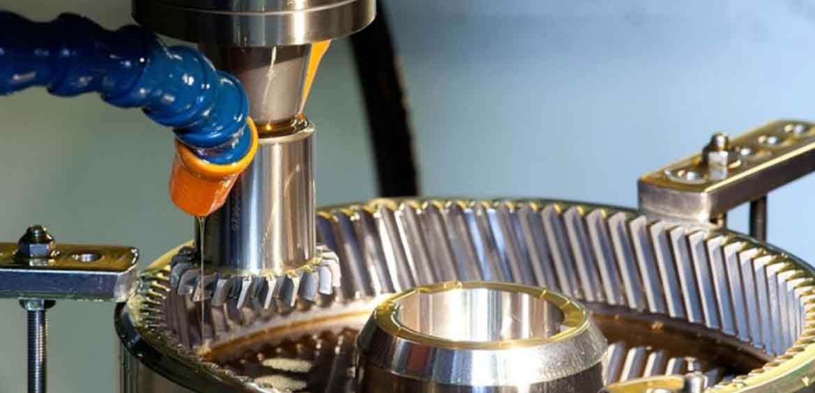
Gear shaping involves a reciprocating motion driven by a crank-slider mechanism, where the spindle is subjected to cyclical radial forces. The radial force \( F \) on the spindle can be derived from kinematic analysis. Let \( L_1 \) be the crank length, \( L_2 \) the connecting rod length, \( \alpha \) the crank angle, and \( \omega \) the angular velocity. The spindle displacement \( y \) is given by:
$$ y = L_1 \sin \alpha + \sqrt{L_1^2 \sin^2 \alpha – L_1^2 + L_2^2} $$
The acceleration \( a \) in the y-direction is:
$$ a = \frac{d^2 y}{dt^2} = -L_1 \omega^2 \sin \alpha + \frac{\omega L_1^2 \cos 2\alpha}{\sqrt{\omega^2 \sin^2 \alpha – L_1^2 + L_2^2}} – \frac{\omega^2 L_1^4 \sin^2 \alpha}{4 (\omega^2 \sin^2 \alpha – L_1^2 + L_2^2)^{3/2}} $$
Using static equilibrium, the radial force components are:
$$ F_y = m(a – g) $$
$$ F_x = m g \tan \theta $$
where \( \theta \) is the angle between the connecting rod and spindle centerline, and \( m \) is the mass. The total radial force \( F \) is:
$$ F = F_x (L_1 + L_2 + c) $$
with \( \cos \theta = \frac{L_2^2 + y^2 – L_1^2}{2 L_2 y} \). In gear shaping machines, this force fluctuates periodically, necessitating a robust hydrostatic bearing design. The oil film stiffness \( S \) for a hydrostatic bearing without circumferential oil return is critical and can be expressed as:
$$ S = \sum s_i $$
where \( s_i \) is the stiffness of each oil chamber. For a capillary-restricted bearing, \( s_i \) is given by:
$$ s_i = \frac{3A(\beta_i – 1)}{\beta_i^2 + \lambda_k \beta_i (\beta_i – 1) \left(1 – \cos \frac{2\pi}{n}\right)} \frac{p_s A_e}{h_{0i}} $$
Here, \( A \) is the oil film non-uniformity coefficient, \( \beta_i \) is the throttling ratio, \( \lambda_k \) is the internal flow coefficient, \( p_s \) is the supply pressure, \( A_e \) is the effective bearing area, and \( h_{0i} \) is the oil film thickness under load. The parameters are calculated as:
$$ A = \frac{\sin \phi_0}{\phi_0} $$
$$ \beta_i = \frac{p_s}{p_{ri}} $$
$$ \lambda_k = \frac{n a (L – a)}{\pi D b} $$
where \( \phi_0 \) is the angle of the oil chamber, \( a \) and \( L \) are axial dimensions, \( D \) is the spindle diameter, and \( n \) is the number of chambers. The chamber pressure \( p_{ri} \) depends on the restrictor and bearing resistances:
$$ p_{ri} = \frac{p_s}{1 + \frac{R_g}{R_{h0}} (1 – A \varepsilon \cos \phi_i)^3} $$
with \( R_g = \frac{128 l_e \eta_t}{\pi d_e^4} \) for capillary restrictors, and \( R_{h0} = \frac{6 \eta_t a}{h_0^3 D \phi_0} \) for the bearing resistance. In gear shaping, maintaining high \( S \) is essential to counteract dynamic loads.
To optimize the hydrostatic spindle for gear shaping, we focus on the oil chamber geometry. The initial bearing parameters are summarized in Table 1, which serves as a baseline for comparison. The oil film thickness is typically 0.02 mm, posing challenges for finite element modeling. We employ a secondary construction method to create a 3D model of the thin oil film, ensuring accurate mesh generation and convergence in simulations. The fluid domain is segmented into four chambers and a thin film region, with meshing done using a fine element size of 0.0005 mm. Boundary conditions include pressure inlets at the oil supply ports and pressure outlets at the axial ends, simulating the actual gear shaping environment. The lubricant is N22 mechanical oil with a dynamic viscosity \( \eta_t = 0.021 \, \text{Pa·s} \) and density \( \rho = 900 \, \text{kg/m}^3 \). The FSI approach couples the fluid dynamics with structural mechanics, mapping oil film pressures onto the spindle surface to compute stresses and deformations.
| Parameter | Value |
|---|---|
| Circumferential seal width \( B \) (mm) | 35 |
| Oil chamber angle \( \phi_0 \) (degrees) | 45 |
| Half-angle of oil chamber \( \phi_1 \) (degrees) | 30 |
| Spindle diameter \( D \) (mm) | 70 |
| Axial seal width \( a \) (mm) | 50 |
| Bearing length \( L \) (mm) | 200 |
| Bearing clearance \( h_0 \) (mm) | 0.02 |
The first optimization scheme involves chamfering the edges of the oil chambers. Sharp edges can cause stress concentrations and flow instabilities, detrimental to gear shaping precision. By adding a radius \( R \) to the circumferential edges, we smooth the transition between chambers and seal lands. The chamfer radius varies from 0 to 2 mm, limited by geometric constraints. The second scheme redesigns the oil chambers into a rectangular-ambulatory-plane shape, increasing the effective area without altering the overall chamber size. This shape enhances pressure distribution and load capacity. We analyze both designs using FSI simulations to evaluate bearing capacity \( T \) and oil film stiffness \( S \). The results, compared to the initial design, show marked improvements.
For the chamfered edge design, the bearing capacity increases marginally with radius \( R \). At \( R = 2 \, \text{mm} \), \( T \) peaks at 3005 N, up from 2992.5 N for the initial design—a 0.4% improvement. The oil film stiffness \( S \) reaches 785.8709 N/μm at \( R = 2 \, \text{mm} \), compared to 784.9667 N/μm initially, a 0.12% gain. While modest, this reduces stress concentrations and extends bearing life in gear shaping machines. The rectangular-ambulatory-plane design yields more significant gains. As the longest side length \( l \) increases to 180 mm, \( T \) rises to 3210.6 N (a 12% increase) and \( S \) to 882.2749 N/μm (a 12.3% increase). This design better distributes loads, crucial for handling the periodic impacts in gear shaping. Table 2 summarizes these outcomes, highlighting the superiority of the rectangular-ambulatory-plane configuration for gear shaping applications.
| Design | Bearing Capacity \( T \) (N) | Oil Film Stiffness \( S \) (N/μm) |
|---|---|---|
| Initial | 2992.5 | 784.9667 |
| Chamfered Edge (\( R = 2 \, \text{mm} \)) | 3000.5 | 785.8709 |
| Rectangular-Ambulatory-Plane (\( l = 180 \, \text{mm} \)) | 3210.6 | 882.2749 |
The FSI simulations reveal stress distributions under load. The initial design shows high stress concentrations at chamber edges, whereas chamfering reduces these peaks, and the rectangular-ambulatory-plane design further smooths stress fields. This is vital for gear shaping, where cyclic loading can lead to fatigue failure. The effective bearing area \( A_e \) is derived from stress maps, validating the stiffness calculations. The oil film pressure fields indicate more uniform distributions in optimized designs, enhancing stability during gear shaping operations.
To verify the optimizations, we conduct an empirical analysis using parameters from the YKW51160 gear shaping machine. The crank length \( L_1 = 201.5 \, \text{mm} \), connecting rod length \( L_2 = 995.8 \, \text{mm} \), and other dimensions are used to compute radial forces. Theoretical calculations via MATLAB yield a maximum radial force of 1071 N, but dynamic simulations in ADAMS account for additional factors, giving a force of 1451 N. This higher value is adopted for validation. The optimized bearing capacities (3005 N for chamfered design and 3210.6 N for rectangular-ambulatory-plane design) exceed 1451 N, ensuring safety. Moreover, the oil film stiffness values (785.8709 N/μm and 882.2749 N/μm) surpass the industry requirement of 600 N/μm for gear shaping spindles, confirming suitability.
The gear shaping process benefits directly from these improvements. With enhanced stiffness and load capacity, the spindle can maintain precision under variable loads, reducing vibrations and improving surface finish in gear teeth. The rectangular-ambulatory-plane design, in particular, offers a substantial boost, making it ideal for heavy-duty gear shaping tasks. The FSI methodology proves effective for such optimizations, providing insights into fluid-structure interactions that analytical formulas might miss. For instance, the oil film thickness variation under load is accurately captured, allowing for refined stiffness estimates.
In summary, this study demonstrates the efficacy of structural optimizations for hydrostatic spindles in gear shaping machines. By leveraging fluid-structure interaction analysis, we show that edge chamfering and rectangular-ambulatory-plane oil chambers can significantly improve bearing performance. The rectangular-ambulatory-plane design stands out, offering up to 12% higher bearing capacity and 12.3% greater oil film stiffness, meeting the demands of dynamic gear shaping environments. Future work could explore other chamber geometries or advanced materials to further enhance gear shaping accuracy and efficiency. As gear shaping continues to evolve for applications like wind energy, such optimizations will be crucial for achieving high-precision, reliable manufacturing.
The integration of computational fluid dynamics and structural analysis via FSI represents a powerful tool for designing hydrostatic components in gear shaping. This approach not only validates theoretical models but also uncovers nuanced behaviors, such as stress reductions and flow improvements. For gear shaping manufacturers, adopting these optimized designs can lead to longer spindle life, reduced maintenance, and higher-quality gear production. Ultimately, the advancements contribute to the broader field of precision machining, where gear shaping plays a foundational role in creating complex mechanical systems.