
In the evolving landscape of mechanical manufacturing, the demand for high-precision components has intensified, driving the need for advanced machining equipment. Gear shaping, a critical process in gear production, relies heavily on the accuracy and efficiency of machines like CNC gear shapers. Traditional mechanical drives, such as crank-slider mechanisms, often exhibit limitations like急回特性 (quick-return characteristics), which can compromise the quality of gear shaping. To address these issues, hydraulic drive systems have emerged as a superior alternative, offering benefits such as stepless speed regulation, high torque output, and enhanced stability. This article delves into the analysis and design of hydraulic main drive systems for large CNC gear shaping machines, focusing on their principles, functional requirements, and optimization strategies. Through detailed discussions, formulas, and tables, I aim to provide a comprehensive overview that underscores the importance of hydraulic systems in modern gear shaping applications.
Gear shaping is a precision machining process that utilizes the generating method to form gear teeth. In this process, a specialized cutting tool, known as a gear shaper cutter, reciprocates linearly along the axis of the workpiece while maintaining a meshing relationship with the gear blank. This motion enables the gradual removal of material to create the desired gear profile. The fundamental movements in gear shaping include the main motion (reciprocation of the cutter), the generating motion (synchronized rotation of the cutter and workpiece), and the feed motion (radial infeed for depth control). The integration of CNC technology has revolutionized gear shaping by enabling automated control over these motions, thereby improving accuracy and reducing errors. However, large-scale gear shaping tasks, such as cutting large-diameter gears, pose challenges like insufficient cutting force and uneven speed distribution. Hydraulic drive systems offer a viable solution by providing robust power transmission and flexible speed adjustments, making them ideal for heavy-duty gear shaping operations.
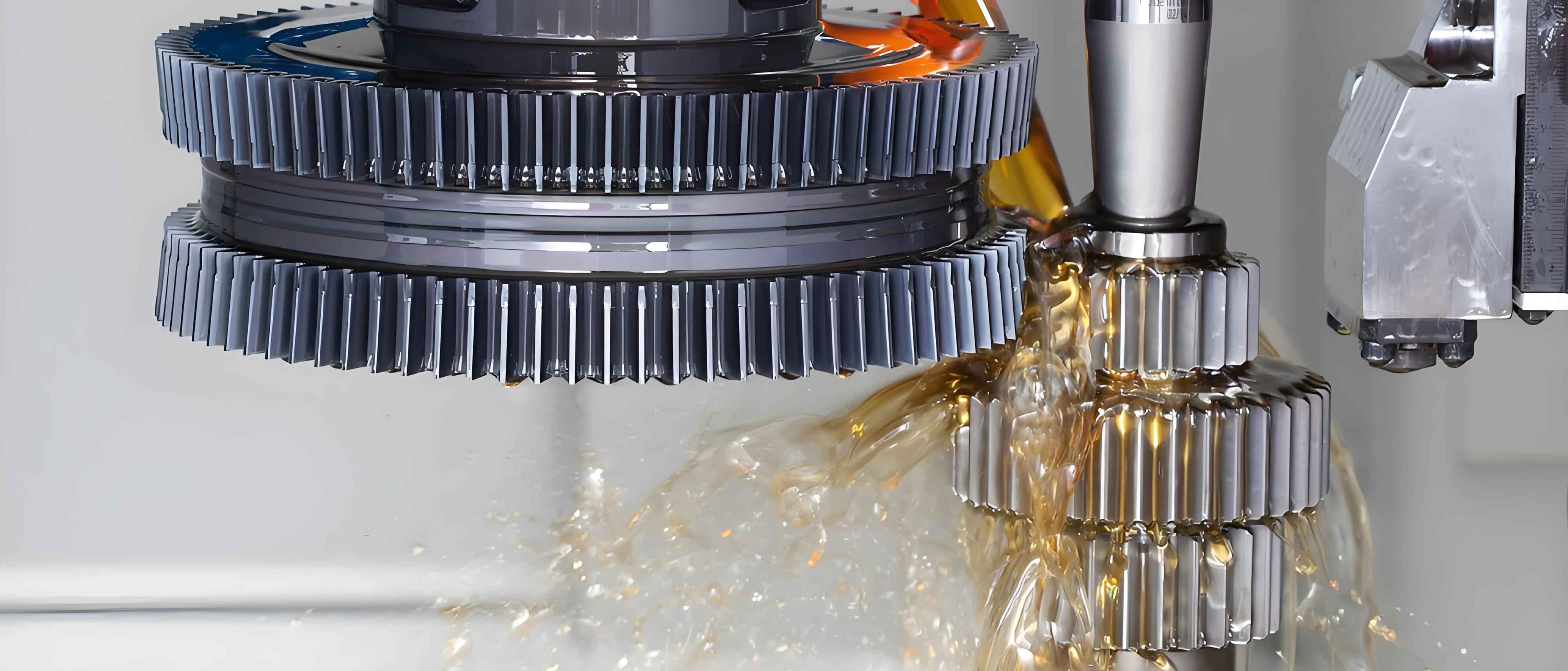
The motion principle of CNC gear shaping machines is rooted in the generating method. The cutter and workpiece simulate the meshing of two gears, with the cutter’s teeth acting as cutting edges. During operation, the cutter performs a linear reciprocating motion along its axis, which constitutes the main cutting action. The generating motion ensures that for each tooth cut on the workpiece, the cutter rotates by a corresponding angle, maintaining the correct gear geometry. This relationship can be expressed mathematically. Let \( N_c \) be the number of teeth on the cutter and \( N_w \) be the number of teeth on the workpiece. The generating motion requires that the angular velocities \( \omega_c \) and \( \omega_w \) satisfy the ratio:
$$ \frac{\omega_c}{\omega_w} = \frac{N_w}{N_c} $$
This ensures precise tooth formation. Additionally, the feed motion involves radial infeed, where the cutter gradually penetrates the workpiece to the full tooth depth. For multiple passes, the infeed amount per pass can be optimized based on material properties and tool geometry. The kinematics of gear shaping can be modeled using equations of motion. For instance, the displacement \( s(t) \) of the cutter during reciprocation can be described as:
$$ s(t) = L \left( \frac{1}{2} – \frac{1}{2} \cos\left(\frac{2\pi t}{T}\right) \right) $$
where \( L \) is the stroke length and \( T \) is the cycle time. This harmonic motion influences cutting speed and force distribution, highlighting the need for controlled drive systems.
To design an effective hydraulic main drive system for large CNC gear shaping machines, it is essential to analyze the functional requirements. These requirements dictate the performance parameters that the system must meet. Below is a summary of key functional needs in table format, emphasizing aspects critical to gear shaping.
| Functional Requirement | Description | Typical Value/Range |
|---|---|---|
| Stroke Length | Maximum cutting length for gear shaping operations. | Effective stroke: 650 mm; Minimum stroke: 100 mm. |
| Maximum Cutting Force | Force required during gear shaping to overcome material resistance. | 36.42 kN (for module 20, depth 15 mm). |
| Cutting Speed | Velocity of cutter during downstroke (cutting) and upstroke (return). | Downstroke max: 12.5 m/min; Upstroke max: 25 m/min. |
| Time Ratio | Ratio of downstroke to upstroke duration for efficient gear shaping. | 2:1 (downstroke:upstroke). |
| Load Balancing | Compensation for weight of moving parts (e.g., cutter axis). | Weight: 800 kg; balanced via hydraulic pressure. |
| Position Control | Precision in stopping at any point during stroke. | Sensor resolution: 0.005 mm. |
| Pressure Monitoring | Monitoring of hydraulic pressures in cylinder chambers. | Integrated pressure sensors for feedback. |
The cutting force in gear shaping is a critical parameter. It can be estimated using the formula:
$$ F_c = A_c \cdot \tau $$
where \( F_c \) is the cutting force, \( A_c \) is the cross-sectional area of cut, and \( \tau \) is the shear stress of the workpiece material. For a gear shaping operation with a module \( m = 20 \) mm and infeed depth \( d = 15 \) mm, the cutting area per stroke can be approximated as:
$$ A_c = m \cdot d \cdot k $$
where \( k \) is a factor accounting for tooth geometry. Assuming \( k \approx 0.0387 \), we get \( A_c = 11.61 \, \text{mm}^2 \). With a shear stress \( \tau = 3137 \, \text{MPa} \), the cutting force computes to \( F_c = 36.42 \, \text{kN} \). This force must be sustained by the hydraulic system to ensure effective gear shaping. Additionally, the speed requirements involve achieving a uniform cutting velocity. The hydraulic system allows for stepless speed adjustment, which can be modeled as:
$$ v(t) = \frac{Q}{A} $$
where \( v(t) \) is the piston velocity, \( Q \) is the flow rate, and \( A \) is the effective area of the hydraulic cylinder. By controlling \( Q \), the speed during gear shaping can be optimized for different materials and tooth profiles.
The design of the hydraulic drive scheme is pivotal for meeting the demands of large CNC gear shaping machines. A typical hydraulic system for gear shaping includes components like hydraulic cylinders, pumps, valves, accumulators, and sensors. The primary goal is to drive the cutter axis reciprocally while providing precise control over motion parameters. The schematic often involves a double-acting hydraulic cylinder connected to the cutter slide. The cylinder’s rod and blind sides are fed with hydraulic fluid via proportional valves, enabling adjustable speeds and forces. For gear shaping applications, the system must incorporate features like regenerative circuits to enhance efficiency during the return stroke. The force balance equation for the hydraulic cylinder can be expressed as:
$$ F_h = P_1 \cdot A_1 – P_2 \cdot A_2 – F_f $$
where \( F_h \) is the hydraulic force, \( P_1 \) and \( P_2 \) are pressures in the rod and blind sides, \( A_1 \) and \( A_2 \) are respective areas, and \( F_f \) is the frictional force. To achieve the desired time ratio of 2:1 for downstroke to upstroke, the area ratio \( A_1/A_2 \) should be optimized, often approaching 1:2. This ensures that the gear shaping process maintains consistent cutting conditions. Moreover, the system includes safety features such as pressure relief valves and lock valves to prevent mechanical failures during sudden stops. The integration of CNC control allows for programmable motion profiles, facilitating complex gear shaping tasks like helical gears or internal gears.
In terms of motion scheme selection, the hydraulic drive offers advantages over mechanical alternatives like crank-slider mechanisms. The latter often suffer from velocity fluctuations, leading to uneven gear shaping quality. Using simulation tools like ADAMS, the velocity profile of a slider in a crank mechanism can be analyzed, revealing peaks and valleys that affect cutting consistency. In contrast, hydraulic systems provide smoother motion, which is crucial for precision gear shaping. The overall motion scheme for a CNC gear shaping machine encompasses the main drive, generating drive, and feed drive. These are coordinated to achieve the desired gear geometry. For instance, the generating motion is typically realized through a servo motor coupled with a worm gear reducer, ensuring synchronized rotation between cutter and workpiece. The feed motion is handled by another servo drive system that controls radial infeed. The interaction of these motions can be represented functionally, as shown in the motion function diagram, where \( Z_p \) denotes the main motion, \( C_f1 \) and \( C_f2 \) represent feed and generating motions, and \( Y_a \) indicates the infeed motion. This integrated approach enhances the versatility of gear shaping machines for various applications.
Key technical indicators for large CNC gear shaping machines are derived from industry standards and performance requirements. Below is a table summarizing these indicators, which guide the design of the hydraulic main drive system. These parameters are essential for ensuring that the machine meets the demands of modern gear shaping processes.
| Technical Parameter | Specification | Remarks |
|---|---|---|
| Maximum Workpiece Diameter | 1600 mm | For external and internal gear shaping. |
| Maximum Module | 16 mm | Determines tooth size capacity. |
| Maximum Tooth Width | 380 mm | Increased for large-scale gear shaping. |
| Stroke Rate | 10–60 strokes/min | Adjustable via hydraulic control. |
| Radial Feed Rate | 0–500 mm/min | Precision infeed for depth control. |
| Table Rapid Traverse | 1 m/min | For positioning during gear shaping setup. |
| Hydraulic Pressure | 5–20 MPa | Operating range for drive system. |
| System Power | 15–30 kW | Depending on gear shaping load. |
These indicators influence the sizing of hydraulic components. For example, the hydraulic cylinder diameter \( D \) can be calculated based on the required force and pressure. Using the formula:
$$ D = \sqrt{\frac{4F_c}{\pi P}} $$
where \( P \) is the operating pressure, we can determine the cylinder size for a given gear shaping force. Assuming \( F_c = 36.42 \, \text{kN} \) and \( P = 10 \, \text{MPa} \), we get \( D \approx 68 \, \text{mm} \). The piston rod diameter \( d \) is often taken as \( 0.5D \) for pressures below 5 MPa, but for higher pressures, it may be larger to withstand buckling loads. The cylinder length \( L_c \) is determined by the stroke length plus allowances for overtravel, typically set to accommodate the maximum gear shaping width. For a stroke of 650 mm, \( L_c \) might be around 800 mm to ensure full range motion. These dimensions are critical for the structural design of the gear shaping machine.
The mechanical system structure of the spindle in a CNC gear shaping machine comprises several subsystems: the main motion system, the generating motion system, and the tool relief motion system. Each subsystem has distinct design considerations tailored to gear shaping requirements. The main motion system, driven hydraulically, includes the hydraulic cylinder, piston rod, cutter axis, and slide. The cylinder must be designed to withstand dynamic loads during reciprocation. The stress on the piston rod can be evaluated using the Euler buckling formula for long columns:
$$ F_{cr} = \frac{\pi^2 E I}{(K L)^2} $$
where \( F_{cr} \) is the critical buckling load, \( E \) is the modulus of elasticity, \( I \) is the moment of inertia, \( K \) is the effective length factor, and \( L \) is the rod length. Ensuring \( F_{cr} > F_c \) prevents failure during gear shaping. The generating motion system involves a worm gear reducer to transmit rotation from the servo motor to the workpiece table. The gear ratio \( i \) is selected based on the generating motion requirement:
$$ i = \frac{N_w}{N_c} \cdot \frac{\omega_m}{\omega_c} $$
where \( \omega_m \) is the motor speed. The worm gear design must account for torque transmission and backlash minimization to maintain accuracy in gear shaping. The tool relief motion system, which retracts the cutter slightly during the return stroke to prevent rubbing, is often implemented via cam mechanisms or auxiliary hydraulic cylinders. The displacement for relief \( \delta \) is small, typically 0.1–0.5 mm, and can be calculated based on cutter geometry and material properties.
Spindle strength verification is a crucial step in ensuring the reliability of the gear shaping machine. The spindle material, such as alloy steel with high tensile strength, must be checked for static and fatigue loads. Using the distortion energy theory (von Mises criterion), the equivalent stress \( \sigma_{eq} \) can be computed as:
$$ \sigma_{eq} = \sqrt{\sigma_x^2 + \sigma_y^2 – \sigma_x \sigma_y + 3\tau_{xy}^2} $$
where \( \sigma_x \) and \( \sigma_y \) are normal stresses, and \( \tau_{xy} \) is the shear stress. For the spindle under combined bending and torsion, the bending stress \( \sigma_b \) from cutting forces and the torsional stress \( \tau_t \) from drive torque are considered. The bending stress is given by:
$$ \sigma_b = \frac{M_b}{Z} $$
where \( M_b \) is the bending moment and \( Z \) is the section modulus. The torsional stress is:
$$ \tau_t = \frac{T}{W_t} $$
where \( T \) is the torque and \( W_t \) is the torsional resistance. Substituting into the von Mises formula, we can assess whether the stress exceeds the allowable limit \( \sigma_{allow} \), which is derived from the material’s yield strength with a safety factor. For fatigue analysis, the modified Goodman diagram can be used to account for fluctuating loads during gear shaping cycles. The endurance limit \( \sigma_e \) is compared to the alternating stress amplitude \( \sigma_a \). If \( \sigma_a > \sigma_e \), redesign may be necessary. These calculations ensure that the spindle can endure the repetitive stresses of gear shaping operations without failure.
In conclusion, the hydraulic main drive system for large CNC gear shaping machines represents a significant advancement in gear manufacturing technology. By leveraging hydraulic power, these systems overcome the limitations of traditional mechanical drives, offering enhanced control, force capacity, and adaptability. The design process involves meticulous analysis of functional requirements, motion principles, and structural integrity, supported by mathematical models and empirical data. Key aspects such as stroke length, cutting force, speed regulation, and system integration are critical to achieving high-quality gear shaping. Through the use of formulas, tables, and systematic approaches, engineers can optimize hydraulic systems for diverse gear shaping applications, from large-diameter gears to precision components. As the industry continues to demand higher efficiency and accuracy, further research into advanced hydraulic components and control algorithms will pave the way for next-generation gear shaping machines. Ultimately, the adoption of hydraulic drives not only improves performance but also contributes to the economic viability of gear production by reducing downtime and enhancing product quality.
To further illustrate the design considerations, let’s summarize some key formulas and parameters in a consolidated table. This table encapsulates the core mathematical relationships involved in hydraulic drive system design for gear shaping machines.
| Parameter | Formula | Application in Gear Shaping |
|---|---|---|
| Cutting Force | \( F_c = A_c \cdot \tau \) | Determines hydraulic force requirement. |
| Hydraulic Cylinder Force | \( F_h = P_1 A_1 – P_2 A_2 – F_f \) | Balances loads during reciprocation. |
| Piston Velocity | \( v = Q / A \) | Controls cutting speed in gear shaping. |
| Stroke Time Ratio | \( t_d : t_u = A_2 : A_1 \) (approx.) | Optimizes cycle efficiency. |
| Cylinder Diameter | \( D = \sqrt{4F_c / (\pi P)} \) | Sizing for gear shaping loads. |
| Buckling Load | \( F_{cr} = \pi^2 E I / (K L)^2 \) | Ensures piston rod stability. |
| Von Mises Stress | \( \sigma_{eq} = \sqrt{\sigma_x^2 + \sigma_y^2 – \sigma_x \sigma_y + 3\tau_{xy}^2} \) | Evaluates spindle strength. |
| Generating Motion Ratio | \( \omega_c / \omega_w = N_w / N_c \) | Maintains tooth geometry accuracy. |
These formulas underscore the interdisciplinary nature of designing hydraulic systems for gear shaping, blending mechanics, hydraulics, and control theory. In practice, iterative simulations and prototype testing are often conducted to refine the design. For instance, computational fluid dynamics (CFD) can model oil flow in hydraulic circuits, while finite element analysis (FEA) assesses structural components under gear shaping loads. Additionally, the integration of sensors and feedback loops enables real-time monitoring, allowing adjustments to pressure and flow rates based on cutting conditions. This adaptive control is particularly beneficial for gear shaping of hardened materials or complex profiles, where consistency is paramount.
Looking ahead, trends in gear shaping technology point toward greater automation and intelligence. Hydraulic systems are evolving with electro-hydraulic proportional valves and digital controllers that offer finer resolution and faster response. These advancements facilitate the implementation of advanced gear shaping strategies, such as variable speed cutting or adaptive feed rates, which can reduce tool wear and improve surface finish. Moreover, the emphasis on sustainability drives the development of energy-efficient hydraulic systems, using variable displacement pumps or regenerative cycles to minimize power consumption during idle strokes. As gear shaping continues to be a cornerstone of gear manufacturing, the role of hydraulic drives will remain pivotal, enabling machines to meet the ever-growing demands for precision, efficiency, and reliability. Through continuous innovation, the future of gear shaping promises even higher levels of performance, contributing to the broader goals of smart manufacturing and industrial advancement.