
In the realm of gear manufacturing, gear shaping stands out as a versatile and indispensable method for producing high-precision gears, especially for internal gears and complex profiles. The advent of Computer Numerical Control (CNC) technology has revolutionized gear shaping, offering enhanced accuracy, flexibility, and efficiency. However, traditional gear shaping machines often rely on mechanical components like spiral guides for helical gear cutting, which can limit performance and increase complexity. In this study, I explore the integration of electronic gearbox principles into CNC gear shaping machines to replace these mechanical linkages, thereby enabling advanced motion control for helical gear shaping. By leveraging software-based electronic gearbox systems, we can achieve precise inner-link transmission structures that facilitate electronic indexing and differential motions, ultimately improving the gear shaping process.
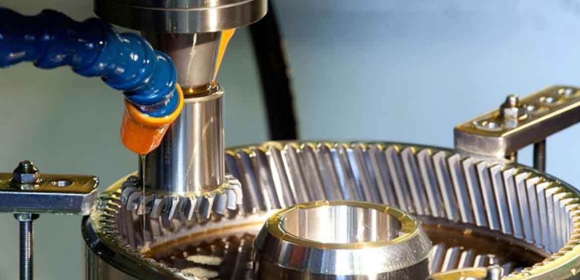
The core of this approach lies in the electronic gearbox, which emulates traditional gear trains through electrical and software means. An electronic gearbox system synchronizes multiple axes of motion by controlling the frequency and phase relationships between motors, eliminating the need for physical gears. This is particularly beneficial in gear shaping, where precise coordination between the cutter spindle and workpiece rotation is crucial for generating accurate gear teeth. In this article, I will delve into the hardware and software foundations of electronic gearboxes, derive motion equations for CNC gear shaping machines, and propose control strategies for electronic indexing and differential synthesis. Additionally, I will address acceleration-deceleration positioning control for the additional rotations required in helical gear shaping, ensuring smooth and error-free operations.
Electronic gearbox systems are fundamentally about achieving synchronized motion control through frequency and phase locking. In hardware implementations, a phase-locked loop (PLL) is commonly used, consisting of a phase detector, loop filter, and voltage-controlled oscillator. This setup ensures that the output signal tracks the input signal with a fixed phase relationship, allowing for precise speed ratio control. For gear shaping applications, we can adapt this principle to synchronize the cutter and workpiece axes. The basic structure of a PLL-based electronic gearbox is shown in the following diagram, where input pulses from a master encoder are processed to generate control signals for a slave motor.
The transmission ratio in such a system is determined by frequency scaling factors. If we denote the input pulse frequency as \( f_1 \) and the output frequency as \( f_2 \), and use frequency dividers and multipliers with coefficients \( M \) and \( N \), the relationship at steady state is given by:
$$ f_1 M = f_2 N $$
Thus, the speed ratio \( i \) becomes:
$$ i = \frac{\omega_2}{\omega_1} = \frac{f_2}{f_1} = \frac{M}{N} $$
This allows for flexible configuration of transmission ratios by adjusting \( M \) and \( N \), which is essential for adapting to different gear parameters in gear shaping. However, hardware electronic gearboxes have limitations, such as integer-only ratios and complexity in implementation. To overcome these, software electronic gearboxes have been developed, where a microprocessor handles pulse processing and control algorithms.
In software electronic gearbox systems, the phase detection is replaced by digital counters and timer interrupts. The master motion pulse frequency \( f_1(t) \) and slave feedback frequency \( f_2(t) \) are sampled over a fixed time period \( T \), and their counts are compared to enforce the desired ratio. Let \( R_+ \) and \( R_- \) represent the counts for master and slave pulses, respectively. At stability, we have:
$$ R_+ M = R_- N $$
This implies \( f_1(t) M = f_2(t) N \), similar to the hardware case. The software approach offers advantages like fractional transmission ratios and integration with servo control algorithms. The processing flow involves periodic interrupts to update counts, apply frequency scaling, and compute error signals for motor control. Below is a table summarizing the comparison between general CNC systems and electronic gearbox systems in the context of gear shaping.
| Aspect | General CNC System | Electronic Gearbox System |
|---|---|---|
| Synchronization Requirement | Relative position synchronization between motions | Speed synchronization with no steady-state error in position |
| Motion Relationship Processing | Interpolation for coordinate increment分配 | Speed ratio control for precise motion信息处理 |
| Application Focus | Machine feed motions | Inner-link transmissions, including main and feed motions |
For gear shaping machines, the inner-link transmission structure must coordinate multiple axes: the cutter reciprocation, cutter rotation, workpiece rotation, and radial feed. The electronic gearbox enables this by implementing electronic indexing for the generating motion and electronic differential for helical gear shaping. In electronic indexing, the cutter spindle and workpiece rotate in a strict ratio to ensure pure rolling at the pitch circle, which is fundamental to gear shaping. The relationship is derived from the gear tooth numbers:
$$ f_2 = f_1 \cdot \frac{\Delta_b}{\Delta_c} \cdot \frac{Z_w}{Z_c} $$
where \( f_1 \) is the pulse frequency for workpiece rotation, \( f_2 \) is for cutter rotation, \( \Delta_b \) and \( \Delta_c \) are pulse equivalents, \( Z_w \) is the workpiece tooth number, and \( Z_c \) is the cutter tooth number. This equation ensures that for each rotation of the workpiece, the cutter rotates proportionally to cut the correct number of teeth, a critical aspect of gear shaping.
When it comes to helical gear shaping, an additional motion is required to generate the helix angle. This is where electronic differential synthesis comes into play. The cutter must undergo an extra rotation as it moves axially, simulating the effect of a spiral guide. The motion relationships for helical gear shaping can be summarized in the following table, which outlines the correspondence between cutter rotation, workpiece rotation, and cutter linear displacement.
| Cutter Rotation (rev) | Workpiece Rotation (rev) | Cutter Linear Displacement (mm) |
|---|---|---|
| \( \frac{Z_w}{Z_c} \pm \frac{S}{T_c} \) | 1 | \( S \) |
| 1 | \( \frac{Z_w}{Z_c} \left(1 \pm \frac{S}{T_w}\right) \) | \( S \) |
Here, \( S \) is the linear displacement per stroke, \( T_w \) is the workpiece lead, and \( T_c \) is the cutter lead, given by \( T_w = \frac{\pi m_n Z_w}{\sin \beta} \) and \( T_c = \frac{\pi m_n Z_c}{\sin \beta} \), with \( m_n \) as the normal module and \( \beta \) as the helix angle. The ± sign indicates the direction of additional rotation for up and down strokes in gear shaping.
To implement this electronically, we need to relate pulse frequencies to these motions. Assuming the linear displacement \( S \) is measured via an encoder on the reciprocating shaft, with \( N_S \) pulses per stroke and a base pulse count \( N_0 \) per revolution, we have:
$$ S = \frac{\pi d N_S}{N_0} $$
where \( d \) is the pitch diameter of the shaft. Substituting into the motion equations, the pulse frequency for cutter rotation \( f_2 \) becomes:
$$ f_2 = f_1 \frac{\Delta_b Z_w}{\Delta_c Z_c} \pm \frac{\pi d N_S \sin \beta}{N_0 \Delta_c m_n Z_c} f_1 \Delta_b $$
If we set \( \Delta_b = \Delta_c \) for simplicity, this reduces to:
$$ f_2 = f_1 \frac{Z_w}{Z_c} \pm \frac{\pi d N_S \sin \beta}{N_0 m_n Z_c} f_1 = f_0 \pm f_d $$
where \( f_0 \) represents the indexing component and \( f_d \) the differential component. This equation highlights the multi-input, single-output nature of helical gear shaping control. In practice, software algorithms combine these pulses: \( f_0 \) is generated by scaling \( f_1 \), and \( f_d \) is derived from the linear motion encoder, with addition or subtraction based on stroke direction. The error between the desired and actual \( f_2 \) is used to drive the cutter spindle motor, ensuring precise synchronization.
The inner-link transmission structure based on software electronic gearbox for CNC gear shaping machines can be visualized as a block diagram where master and slave encoders feed into counters, with software performing frequency scaling and differential synthesis. This setup replaces mechanical differential gears, simplifying the machine structure and enhancing rigidity and accuracy. Moreover, it allows for real-time adjustment of parameters like helix angle and tooth number, making gear shaping more flexible for custom gear production.
However, the sudden changes in additional rotation direction during reciprocation pose challenges for motion control. Specifically, at the reversal points, the speed change of \( 2f_d \) can lead to infinite acceleration demands, causing motor stalling or errors. To address this, acceleration-deceleration positioning control must be applied. The ideal speed curve for the cutter spindle shows instantaneous reversals, which are impractical. Instead, we adopt a segmented approach: dividing the stroke into acceleration, constant-speed, and deceleration zones. This ensures smooth transitions while maintaining the total pulse count per stroke.
Let \( T \) be the time for one complete reciprocation cycle, given by \( T = 60 / n \), where \( n \) is the main motor speed in rpm. The additional pulse count per half-stroke is \( N_f = f_d T / 2 \). To prevent step loss, the control system must guarantee that the total steps in forward and reverse strokes match the required values. The acceleration-deceleration profile can be designed using linear or S-curve methods, with the total step数 preserved. For instance, in linear acceleration, the speed increases in discrete steps over time, and the step count per segment is calculated as \( G_i = f_i \cdot t_i \), where \( f_i \) is the frequency at level \( i \) and \( t_i \) is the time increment. The total steps during acceleration are the sum of these segments.
$$ S_{\text{acc}} = \sum_{i=1}^{N} G_i $$
In implementation, to reduce computational load, a look-up table method is often used. Pre-calculated speed data for each acceleration level are stored in an array, and the controller reads these values during runtime to update motor commands. This approach ensures efficient real-time performance while maintaining precision in gear shaping operations.
Error analysis is crucial for software electronic gearbox systems. Due to timer interrupt sampling, pulse counts may have an error of ±1 count, affecting the transmission ratio accuracy. The maximum and minimum possible ratios are:
$$ i_{\text{max}} = \frac{R_- + 1}{R_+ – 1}, \quad i_{\text{min}} = \frac{R_- – 1}{R_+ + 1} $$
To mitigate this, we can increase encoder resolution, raise master speed, or extend the sampling period \( T \), within the limits of servo control bandwidth. This ensures that the gear shaping process maintains high accuracy, essential for producing quality gears.
In summary, the integration of electronic gearbox technology into CNC gear shaping machines offers significant advantages for helical gear production. By using software-based systems, we achieve electronic indexing and differential motions without mechanical components, enhancing flexibility and precision. The motion equations derived here provide a foundation for control algorithm development, while acceleration-deceleration strategies ensure smooth operation. Future work could focus on adaptive control for varying load conditions and integration with IoT for smart manufacturing in gear shaping. As gear shaping continues to evolve, electronic gearbox-based systems will play a pivotal role in advancing this critical manufacturing process.
To further illustrate the motion relationships in gear shaping, below is a comprehensive table summarizing key equations and parameters for both spur and helical gear shaping based on electronic gearbox principles.
| Parameter | Symbol | Equation or Description | Role in Gear Shaping |
|---|---|---|---|
| Workpiece Pulse Frequency | \( f_1 \) | Input from workpiece encoder | Master reference for synchronization |
| Cutter Pulse Frequency | \( f_2 \) | \( f_2 = f_0 \pm f_d \) | Slave control for combined motions |
| Indexing Component | \( f_0 \) | \( f_0 = f_1 \frac{Z_w}{Z_c} \) (with equal pulse equivalents) | Ensures correct tooth generation in gear shaping |
| Differential Component | \( f_d \) | \( f_d = \frac{\pi d N_S \sin \beta}{N_0 m_n Z_c} f_1 \) | Adds helical motion in gear shaping |
| Linear Displacement | \( S \) | \( S = \frac{\pi d N_S}{N_0} \) | Cutter stroke per cycle in gear shaping |
| Transmission Ratio | \( i \) | \( i = \frac{M}{N} \) in electronic gearbox | Configurable for different gear shaping tasks |
| Acceleration Steps | \( S_{\text{acc}} \) | \( S_{\text{acc}} = \sum f_i t_i \) | Controls smooth speed changes in gear shaping |
This table encapsulates the essential variables and their interrelationships, facilitating a deeper understanding of the control system design for gear shaping machines. By repeatedly applying these principles in gear shaping operations, manufacturers can achieve higher productivity and accuracy, underscoring the importance of electronic gearbox technology in modern gear production.