
In the modern manufacturing landscape, the process of gear milling, particularly for spiral bevel gears, plays a critical role in industries such as automotive, aerospace, and heavy machinery. Traditionally, spiral bevel gear milling machines have relied on complex mechanical transmission chains, which, while functional, impose limitations on precision, flexibility, and efficiency. With the rapid advancement of computer and numerical control technologies, there is a compelling opportunity to retrofit these machines to enhance their capabilities. In this paper, we explore the methodologies and benefits of implementing CNC systems into existing spiral bevel gear milling machines, focusing on the transformative impact on the gear milling process. Through detailed technical discussions, formulas, and tables, we aim to provide a roadmap for such retrofits, emphasizing the repeated theme of gear milling as a core manufacturing activity.
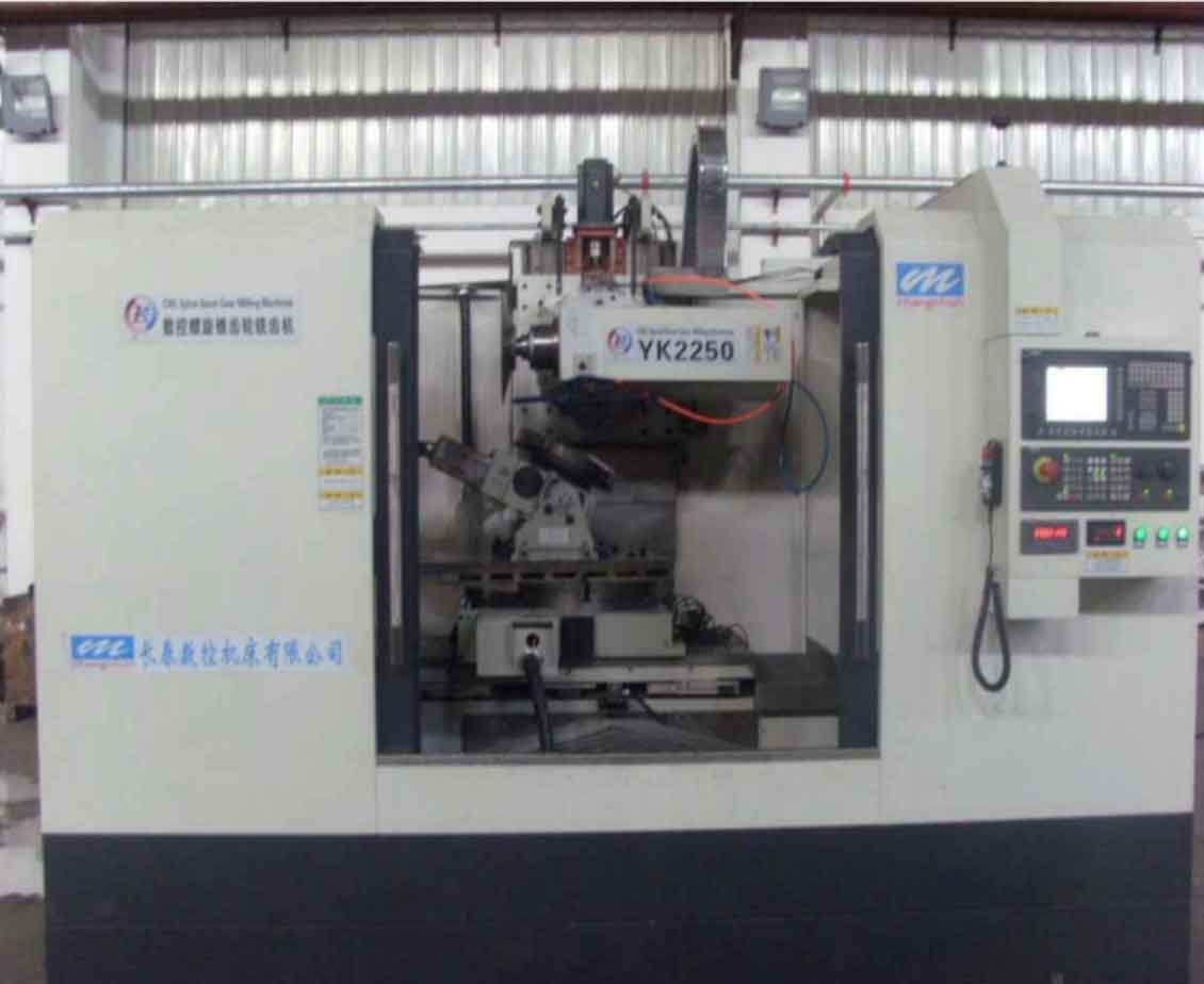
The current state of spiral bevel gear milling machines, especially in many manufacturing facilities, involves a mix of domestic and imported models, such as the Y2280 and similar variants. These machines predominantly operate based on mechanical linkages, including change gears (挂轮) for adjusting speeds and feeds. While this mechanical approach has served the industry for decades, it introduces inefficiencies in setup time, computational overhead for gear calculations, and limited adaptability to new designs. The advent of CNC technology has revolutionized ordinary machine tools like lathes and mills, and it is now imperative to extend these advancements to specialized gear milling equipment. By retrofitting with CNC systems, we can unlock higher automation, improved accuracy, and greater flexibility in gear milling operations, thereby addressing the evolving demands of precision engineering.
The core of the CNC retrofit for spiral bevel gear milling machines lies in reengineering the main motion, feed, indexing, and roll motions. Traditionally, the main motion is driven by a standard AC motor coupled with change gears to achieve varying cutting speeds. In the retrofit approach, we replace this with an AC variable-frequency motor. This modification allows for a fixed gear transmission chain, eliminating the need for change gears, while the variable-frequency motor enables precise speed control through electronic adjustment. This simplification not only reduces mechanical complexity but also enhances the responsiveness of the gear milling process, allowing for optimal cutting conditions across different materials and gear geometries. The emphasis on gear milling here is clear, as speed control directly influences tooth surface quality and tool life.
For the feed, indexing, and roll motions, which are crucial in shaping the spiral bevel gear teeth, the mechanical systems are replaced with servo-driven components. Specifically, the feed motion can be implemented using an AC servo motor coupled with a ball screw and nut assembly, providing precise linear displacement. The indexing and roll motions, which involve rotational adjustments for tooth spacing and cutter path simulation, are handled by separate AC servo motors driving worm gear pairs. This electromechanical integration, as illustrated in the system diagram, decouples the motions from mechanical linkages, enabling independent control via CNC commands. The transformation fundamentally alters the gear milling dynamics, allowing for programmable adjustments that were previously labor-intensive through manual gear changes.
To quantify the benefits, we delve into the mathematical foundations of spiral bevel gear milling. One key aspect is the transmission ratio between the workpiece and the cradle (摇台), which governs the relative motion during cutting. In traditional setups, this ratio is set using change gears based on complex calculations. With CNC retrofit, we can compute this ratio digitally and execute it via servo motors. For orthogonal gears (shaft angle of 90 degrees), the transmission ratio \( i_{tk} \) can be expressed as:
$$ i_{tk} = \frac{z_2}{z_1} $$
where \( z_1 \) is the number of teeth on the pinion (小齿轮) and \( z_2 \) is the number of teeth on the gear (大齿轮). This formula simplifies the initial setup, but in practice, additional factors such as spiral angle and pressure angle may modify the ratio. The cradle swing angle \( \theta \), which determines the range of cutter motion, can be estimated as:
$$ \theta = 180^\circ \cdot \frac{z_2}{z_1} $$
However, for accurate gear milling, a more precise calculation is often required, incorporating the gear geometry. The adjusted cradle swing angle \( \theta_c \) might be derived from:
$$ \theta_c = \theta \cdot i_{tk} \cdot k $$
where \( k \) is a correction factor based on the machine kinematics and cutter profile. The number of indexing cycles \( N \) per cutting cycle is another critical parameter, given by:
$$ N = \frac{360^\circ}{z_1} $$
These formulas, while foundational, are just the starting point. In CNC-controlled gear milling, they are embedded in the control software, allowing for real-time adjustments and eliminating the need for manual recalculations.
To further illustrate the computational aspects, Table 1 summarizes key parameters and their formulas in both traditional and CNC-retrofitted gear milling systems. This table highlights the reduction in manual steps and the integration of digital controls.
| Parameter | Traditional Gear Milling (Mechanical) | CNC-Retrofitted Gear Milling |
|---|---|---|
| Transmission Ratio (\( i_{tk} \)) | Set via change gears; calculated manually | Computed digitally; set via servo motor control |
| Cradle Swing Angle (\( \theta \)) | Estimated and adjusted with gears | Programmed directly in CNC; adjustable in real-time |
| Indexing Cycles (\( N \)) | Determined by mechanical dividers | Controlled by servo motor with high precision |
| Feed Rate | Adjusted with feed change gears | Programmed as CNC axis motion; variable during operation |
| Contact Pattern Correction | Requires physical gear changes and trials | Modified via software parameters; no hardware changes |
The advantages of retrofitting spiral bevel gear milling machines with CNC systems are multifaceted. First, the elimination of change gears drastically reduces setup time and complexity. In traditional gear milling, selecting and installing the correct change gears involves tedious calculations and physical labor, often leading to errors and rework. With CNC, these gears are replaced by fixed transmission elements, and all motions are controlled through software. This shift not only streamlines the gear milling process but also minimizes human error, enhancing overall consistency in gear production.
Second, the computational burden associated with gear milling is significantly alleviated. Spiral bevel gear design involves numerous formulas and parameters, such as tooth geometry, pressure angles, and spiral curves. In mechanical systems, each adjustment requires recalculating gear ratios and swing angles. With CNC retrofit, we only need preliminary calculations for programming, which are then input into the control system. For instance, the basic transmission ratio and swing angle are computed as above, but the CNC software handles interpolations and dynamic adjustments during the gear milling operation. This capability is particularly beneficial for small-batch or custom gear production, where flexibility is paramount.
Third, the retrofit enables superior control over the contact pattern, which is critical for gear performance in applications like automotive differentials. In traditional gear milling, modifying the contact pattern involves physically changing gears or adjusting mechanical linkages, a time-consuming process that often requires trial-and-error testing. With CNC, adjustments are made by altering program data on the display interface, allowing for rapid iteration and optimization. This flexibility enhances the quality of gear milling, ensuring that gears meet stringent tolerances for noise, vibration, and durability.
From a technical perspective, the integration of CNC systems involves selecting appropriate components. For the main motion, an AC variable-frequency motor with a power rating matching the original machine is used, coupled with a fixed gear reduction to maintain torque. The feed motion employs a high-precision ball screw driven by an AC servo motor, with linear encoders for closed-loop feedback. The indexing and roll motions use servo motors with worm gear reducers, providing the necessary resolution for angular positioning. The control system can be based on popular CNC platforms like Siemens SINUMERIK or Fanuc, configured to handle the multi-axis coordination required in gear milling. These systems manage the synchronous movement of the workpiece, cradle, and saddle, while the cutter speed is regulated by the variable-frequency motor. This orchestration transforms the gear milling machine into a flexible manufacturing unit capable of producing a wide range of spiral bevel gears.
To elaborate on the gear milling process, we consider the kinematic chain in a retrofitted machine. The relationship between the cutter rotation, workpiece rotation, and cradle swing is governed by differential equations that the CNC solves in real-time. For example, the roll motion simulates the generation of the tooth profile, and its equation can be expressed as:
$$ \phi_w = i_{tk} \cdot \phi_c + \Delta \phi $$
where \( \phi_w \) is the workpiece rotation angle, \( \phi_c \) is the cradle rotation angle, and \( \Delta \phi \) is a correction term for spiral angle effects. In CNC gear milling, this equation is implemented as a software algorithm, allowing for seamless adjustments. Additionally, the feed motion along the gear axis is synchronized with these rotations to achieve the desired tooth depth and taper. The precision of this synchronization is key to achieving high-quality gear milling results, as any deviation can lead to tooth errors and poor meshing.
Another significant aspect is the tooling used in gear milling. In spiral bevel gear production, cutters such as face mills or profile cutters are employed, and their geometry must match the gear design. With CNC retrofit, the cutter path can be optimized through programming, reducing wear and improving surface finish. For instance, trochoidal or adaptive tool paths can be implemented to distribute cutting forces evenly, extending tool life in gear milling operations. This level of control is unattainable in mechanical systems, where the cutter path is fixed by the machine kinematics.
Table 2 compares the performance metrics before and after CNC retrofit, emphasizing the enhancements in gear milling efficiency and quality. This table underscores the transformative impact of numerical control on traditional processes.
| Metric | Pre-Retrofit (Mechanical) | Post-Retrofit (CNC) |
|---|---|---|
| Setup Time for New Gear | Several hours (gear calculations and changes) | Less than 30 minutes (programming and input) |
| Positioning Accuracy | ±0.05 mm (due to mechanical backlash) | ±0.005 mm (servo feedback control) |
| Surface Finish (Ra) | 1.6–3.2 μm | 0.8–1.6 μm |
| Flexibility for Design Changes | Low (requires hardware modifications) | High (software adjustments only) |
| Energy Consumption | Higher (inefficient mechanical drives) | Lower (optimized motor control) |
The economic implications of CNC retrofit are also noteworthy. While the initial investment in servo motors, CNC systems, and installation may be substantial, the long-term benefits include reduced labor costs, lower scrap rates, and increased machine utilization. In gear milling, where precision components are often high-value, even marginal improvements in quality can lead to significant savings in downstream assembly and warranty claims. Moreover, the retrofit extends the lifespan of existing machines, aligning with sustainable manufacturing practices by reducing the need for new equipment.
In terms of implementation, the retrofit process involves several steps: mechanical disassembly of old transmission elements, installation of new drives and feedback devices, integration of the CNC system, and calibration. We recommend a phased approach, starting with the main motion and gradually incorporating the feed and indexing axes. During calibration, laser interferometry or ballbar tests can be used to verify geometric accuracy, while test cuts on sample gears ensure that the gear milling performance meets specifications. The software setup involves configuring the CNC parameters for the specific machine kinematics, often using post-processors that translate gear design data into machine commands.
Looking forward, the future of gear milling lies in further integration with digital technologies. For example, additive manufacturing could be combined with CNC gear milling to produce hybrid gear components, or IoT sensors could enable predictive maintenance on retrofitted machines. The concept of Industry 4.0, with its emphasis on connectivity and data analytics, can enhance gear milling by monitoring process variables in real-time and adjusting parameters autonomously for optimal results. Additionally, advancements in CAM software will simplify the programming for complex gear geometries, making CNC-retrofitted machines even more accessible to small and medium enterprises.
In conclusion, the CNC retrofit of spiral bevel gear milling machines represents a paradigm shift in gear manufacturing. By replacing mechanical transmission chains with electronically controlled servo drives, we achieve unprecedented levels of precision, flexibility, and efficiency in gear milling. The elimination of change gears, reduction in computational overhead, and ease of contact pattern adjustment are just a few of the benefits that underscore the value of this transformation. As industries continue to demand higher-quality gears with shorter lead times, retrofitting existing machines with CNC systems offers a viable and cost-effective solution. Through continued innovation and adoption, the gear milling process will remain at the forefront of advanced manufacturing, driving progress in sectors such as automotive, aerospace, and beyond. The journey from mechanical to digital control in gear milling is not just an upgrade; it is a necessary evolution to meet the challenges of modern engineering.
To further explore the technical depth, we can derive additional formulas relevant to gear milling. For instance, the tooth profile of a spiral bevel gear can be described using differential geometry. The position vector of a point on the tooth surface, in the workpiece coordinate system, can be expressed as:
$$ \mathbf{r}(u,v) = \begin{bmatrix} x(u,v) \\ y(u,v) \\ z(u,v) \end{bmatrix} $$
where \( u \) and \( v \) are parameters related to the cutter path and gear geometry. In CNC gear milling, this surface is generated by the coordinated motion of the cutter and workpiece, governed by the machine kinematics. The equation of meshing, which ensures proper contact between gear teeth, is given by:
$$ \mathbf{n} \cdot \mathbf{v}_{12} = 0 $$
where \( \mathbf{n} \) is the normal vector to the tooth surface and \( \mathbf{v}_{12} \) is the relative velocity between the cutter and workpiece. This condition is implicitly satisfied in CNC programming through accurate path planning. Moreover, the cutting forces in gear milling can be modeled to optimize tool life and surface integrity. A simplified force model might be:
$$ F_c = K_c \cdot a_p \cdot f_z $$
where \( F_c \) is the cutting force, \( K_c \) is a material-specific constant, \( a_p \) is the depth of cut, and \( f_z \) is the feed per tooth. In CNC systems, these parameters can be adjusted dynamically based on sensor feedback, ensuring stable gear milling operations even with varying material properties.
Another aspect is the thermal management during gear milling, as excessive heat can lead to tool wear and gear distortion. With CNC retrofit, cooling strategies can be integrated into the program, such as varying the cutter speed or implementing intermittent cuts. The thermal model might involve heat generation rates derived from the cutting power:
$$ P_c = F_c \cdot v_c $$
where \( P_c \) is the cutting power and \( v_c \) is the cutting speed. By monitoring temperature through embedded sensors, the CNC system can adapt the gear milling process to maintain optimal conditions, thereby enhancing both quality and productivity.
In summary, the CNC retrofit of spiral bevel gear milling machines is a comprehensive endeavor that touches upon mechanical, electrical, and software engineering. It revitalizes legacy equipment, making it competitive in today’s fast-paced manufacturing environment. The repeated emphasis on gear milling throughout this discussion highlights its centrality to industrial progress. As we continue to refine these retrofits, we anticipate even greater advancements in accuracy, speed, and adaptability, solidifying gear milling as a cornerstone of precision machining.