
As a seasoned engineer specializing in gear manufacturing, I have spent decades perfecting the art and science of gear milling, particularly for spiral bevel gears. The processes of gear milling and subsequent grinding are critical for achieving high precision, durability, and optimal performance in power transmission systems. In this article, I will share my first-hand insights into the detailed procedures, adjustments, and quality controls involved in gear milling, drawing from extensive hands-on experience. Gear milling is not just a machining step; it is a foundational activity that dictates the functional efficacy of gears in applications ranging from automotive differentials to industrial machinery. I will delve into the nuances of setup, tooling, calculations, and troubleshooting, emphasizing the repeated importance of gear milling throughout. To illustrate practical aspects, I will incorporate tables summarizing key parameters and mathematical formulas to explain underlying principles. Remember, successful gear milling hinges on meticulous attention to every detail, from initial adjustments to final inspections.
The journey of gear milling begins with thorough preparation. Based on process documentation and adjustment cards, I always ensure that the correct cutting tools and equipment are selected. For spiral bevel gear milling, this typically involves acquiring the appropriate cutter heads and fixtures as specified. The adjustment card serves as a blueprint, outlining parameters such as cutter position, workpiece position, machine bed position, indexing, and roll ratios. These parameters are pivotal for accurate tooth formation. In my practice, I meticulously follow these guidelines to avoid errors that could compromise gear quality. Gear milling requires a harmonious integration of machine settings and tool geometry, and even minor deviations can lead to significant defects in the final product.
One of the first steps in gear milling is adjusting the machine according to the parameters set on the adjustment card. This includes setting the cutter location, gear blank location, and machine bed location. Additionally, the indexing mechanism and roll ratio must be configured using change gears. The selection of change gears is crucial; I always verify the gear teeth numbers against the card, ensuring the imprints face outward for easy inspection. The backlash between gears should be maintained within a specific range, typically around 0.05 to 0.10 mm, to ensure smooth operation without excessive play. After adjustments, I double-check all fastening screws and nuts to prevent loosening during operation. Below is a table summarizing common adjustment parameters in gear milling:
| Parameter | Typical Range | Importance in Gear Milling |
|---|---|---|
| Cutter Position | Based on cutter diameter and tooth profile | Determines tooth depth and shape accuracy |
| Workpiece Position | Adjustable via horizontal and vertical offsets | Affects tooth contact pattern and alignment |
| Roll Ratio | Calculated from gear geometry and machine constants | Controls the relative motion between cutter and blank for spiral tooth generation |
| Indexing | Governed by change gears or electronic control | Ensures equal spacing of teeth around the gear circumference |
| Cutting Speed | 20–40 m/min for high-speed steel cutters | Influences tool life, surface finish, and productivity in gear milling |
Cutting speed selection is a critical aspect of gear milling. For high-speed steel cutter heads, I generally choose speeds between 20 and 40 meters per minute, depending on the workpiece material. The formula for cutting speed (V) in meters per minute is given by:
$$ V = \frac{\pi \times D \times N}{1000} $$
where \( D \) is the cutter diameter in millimeters and \( N \) is the spindle speed in revolutions per minute. This relationship helps optimize gear milling operations for efficiency and tool longevity. Additionally, feed rates are adjusted using change gears to control material removal rates. Proper speed and feed settings prevent tool wear and ensure consistent tooth geometry across batches.
When setting up change gears, I always disconnect the machine power to ensure safety. The gears must be installed with their teeth number markings facing outward for verification. After mounting, I check the meshing clearance by feel or using a dial indicator, aiming for a backlash of approximately 0.05–0.10 mm. Once all gears are in place, I confirm their active and passive positions according to the adjustment card before closing covers and doors. This rigorous approach minimizes errors in gear milling that could arise from incorrect gear engagement.
After mechanical adjustments, I proceed to power up the machine. Starting the hydraulic system first, I monitor pressure gauges to ensure all circuits are operating within normal ranges—typically between 4 to 6 MPa for most gear milling machines. A point check of machine movements is performed via jogging to verify correct motion trajectories before initiating full automatic cycles. It is imperative never to disengage hydraulic power under load, as this can cause sudden shifts and damage to the workpiece or tooling. Gear milling relies heavily on stable hydraulic pressure for consistent feed and positioning.
Tool setup is another cornerstone of effective gear milling. The cutter head’s internal bore and rear face, along with the machine’s tool spindle, must be impeccably clean to avoid misalignment. Upon mounting the cutter head, I use a manual checking attachment and a dial indicator to align the cutter tips to a common plane. The allowable deviation is usually within 0.005 mm. Furthermore, I adjust the radial runout of identical cutter blades to be less than 0.01 mm. These precision adjustments are vital for uniform tooth profile generation during gear milling. A tool setting gauge is then employed to verify the cutter tip plane relative to the machine bed, facilitating accurate depth-of-cut distribution.
For workpiece orientation, I set the rotary table angle according to the root cone angle specified on the part drawing. This angle ensures that the gear blank is correctly tilted for machining the spiral teeth. The installation distance, critical for proper gear meshing, is calculated by adding dimensions from the fixture—either marked values or实测 (measured directly)—to the drawing specifications. In fine gear milling, I meticulously control horizontal workpiece position and bed position adjustments for forward or backward movements to achieve exact tooth engagement characteristics. The formula for installation distance (A) can be expressed as:
$$ A = A_{\text{drawing}} + \Delta F $$
where \( \Delta F \) is the fixture offset. This calculation is integral to gear milling accuracy.
When更换 (replacing) the workpiece spindle taper sleeve, I clean both the spindle’s internal taper and the sleeve’s external surfaces, applying a thin film of clean oil. The sleeve is hand-pressed into place, ensuring a gap of about 0.05–0.10 mm between the sleeve and spindle face before tightening. This gap elimination after clamping indicates good taper contact. I avoid using hard tools for knocking to prevent damage. Such practices preserve spindle integrity, which is essential for repeatable gear milling outcomes.
In gear milling of paired gears, the gear with more teeth is designated as the larger member. If tooth counts are equal (i.e., transmission ratio = 1), the adjustment card specifies which gear is larger. I always mill the larger gear first, then the smaller gear to match it. During rough gear milling, I mark adjacent teeth on the larger gear’s back cone with punch marks and double punch marks on a tooth of the smaller gear for pairing identification. These marks facilitate subsequent alignment in finishing operations. Gear milling sequence thus influences final meshing quality.
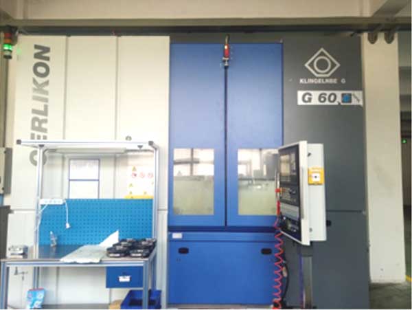
Fine gear milling involves pairing the smaller gear with the larger one using these marks. On a rolling tester, I apply marking compound to assess contact patterns under light load. The installation distance and backlash are recorded for downstream processes. Throughout cutting, I adjust coolant nozzles to direct ample flow at the tool-workpiece interface, reducing heat and improving surface finish. When cutter tip wear reaches 0.2–0.3 mm, I replace or re-sharpen blades promptly to avoid excessive wear and maintain low surface roughness. Gear milling productivity and quality are directly tied to tool maintenance.
Transitioning to gear grinding, the process refines tooth surfaces after gear milling to achieve higher accuracy and hardness. Change gear adjustments are equally critical here. Before installation, I inspect gears for nicks or scratches, cleaning them thoroughly. Gears should mount without tilting or over-tightening, with meshing clearance checked via dial indicator—allowable values around 0.05–0.10 mm. Markings must face outward for verification. Grinding speed and feed change gears are selected based on the machining method or machine manual. Indexing gears or dividing plates are chosen according to tooth count and machine constants, ensuring zero error. Roll ratio gears for grinding affect tooth profile accuracy; I compute these to at least five decimal places to match the cradle and blank speed ratios for precise tooth surface generation. The roll ratio \( R \) is given by:
$$ R = \frac{N_{\text{cradle}}}{N_{\text{blank}}} = f(Z_1, Z_2, \beta) $$
where \( Z_1 \) and \( Z_2 \) are gear teeth numbers and \( \beta \) is the spiral angle. This precision is paramount in gear grinding after initial gear milling.
Drum mechanism adjustments require accurate positioning of rough and finish rollers. The cradle angle is set to define the starting point of oscillatory motion, ensuring sufficient swing to cover the entire tooth surface during grinding. I adjust tool position, workpiece position, and bed position to guarantee correct tooth surface磨削 (grinding). Based on material, grinding mode, roughness requirements, and productivity, I select appropriate grinding wheels. Wheels are inspected for cracks by tapping—a clear ring indicates soundness—then balanced on flanges. Balancing can be dynamic or static; new wheels undergo two balances: first after mounting, then after dressing. Dressing the wheel’s inner and outer edges with a secure, sharp diamond tool is done evenly without dwelling in the working zone. After mounting, I verify wheel position, run a test cycle, and ensure guards are in place. Wheel peripheral speed should not exceed 35 m/s or the wheel’s rated maximum. During testing, I stand clear of the wheel’s rotational path.
Fixture installation precedes workpiece mounting. I clean fixtures of burrs, seat them into the spindle, and check locational runout and end face alignment. Depending on gear accuracy grade, tolerances are kept within 0.005–0.010 mm. Similar to gear milling, when replacing spindle taper sleeves, I clean surfaces, apply oil, and hand-press for a 0.05–0.10 mm pre-tightening gap. Tightening eliminates this gap, confirming good taper fit—no hammering allowed. Installation distance control mirrors that in gear milling, adding fixture offsets to drawing values for precise轮位 (wheel position).
Before grinding, with machine传动 (drive) enabled, I start the wheel and jog the machine to bring the wheel near the gear, running several cycles to confirm accuracy. For paired gears, the larger gear (by tooth count or card designation) is ground first, then the smaller one matched to it. If gears have common divisors, after fine gear milling of the larger gear, I measure tooth精度 (precision) to find the optimal position, marking adjacent teeth on the back cone with hard stamps or electric engraving. The smaller gear is similarly marked post-grinding for paired mating, ensuring assembly consistency. Fine gear milling of the smaller gear is配 (matched) to the larger gear using rolling tests with marking compound, verifying installation distance and backlash while adjusting contact patterns.
Coolant flow must be abundant at the grinding interface to prevent thermal damage. On certain磨齿机 (gear grinding machines), I regularly check accumulator gas pressure, replenishing if low to maintain system stability. To achieve uniform tooth slots, grinding covers not only tooth flanks but also slot bottoms and root fillets. For even磨量 (grinding allowance) distribution, the preceding gear milling process must use identical calculation and adjustment methods. Allowance per side typically does not exceed 0.15 mm. Avoiding burn and roughness issues requires ample coolant; if burning occurs, I review workpiece hardness, cracks, and grinding parameters. Grinding speeds generally range from 25 to 35 m/s, but for gears with节锥角 (pitch cone angles) over 70°, I reduce speeds to 20–25 m/s to prevent annealing.
Contact pattern analysis is vital for gear performance. Ideal patterns under light load are elliptical, with clearance at edges to prevent edge contact. This elliptical局部接触区 (local contact zone) is achieved by modifying theoretical conjugate surfaces; only the midpoint contacts in theory after corrections. Poorly machined surfaces exhibit defects, necessitating careful analysis and adjustment. When contact issues arise, I investigate: approximations in cutting theory, errors in machine adjustments or calculations, improper tool参数 (parameter) selection, and几何精度 (geometric accuracy) of machine, tools, arbors, and blanks. Corrections focus on refining the smaller gear’s finishing parameters based on the larger gear’s profile. Gear milling lays the groundwork for these adjustments.
For hard-faced gears, such as those with hardness above 50 HRC, I employ negative-rake carbide滚刀 (hob) for finish hobbing, which can boost efficiency by 30–50% and save costs. The principles of gear milling extend here, emphasizing tool geometry and cutting dynamics. Below is a table comparing key aspects of gear milling and grinding:
| Aspect | Gear Milling | Gear Grinding |
|---|---|---|
| Primary Purpose | Rough and semi-finish tooth generation | Finish tooth surface refinement and hardening |
| Tool Type | Cutter heads with inserted blades | Grinding wheels (dish or cup type) |
| Accuracy Achievable | IT7–IT9 grades | IT5–IT7 grades |
| Surface Roughness | Ra 1.6–3.2 μm | Ra 0.4–0.8 μm |
| Key Adjustments | Cutter position, roll ratio, indexing | Wheel position, roll ratio, dressing parameters |
| Coolant Requirement | Moderate for chip evacuation and cooling | High to prevent thermal damage and wheel loading |
Mathematically, the tooth profile in gear milling can be modeled using differential geometry. For a spiral bevel gear, the tooth surface equation involves parameters derived from cutter geometry and machine kinematics. For instance, the surface vector \( \mathbf{r}(u,v) \) might be expressed as:
$$ \mathbf{r}(u,v) = \mathbf{r}_0 + u \cdot \mathbf{t} + v \cdot \mathbf{n} $$
where \( \mathbf{r}_0 \) is a reference point, \( \mathbf{t} \) is the tangent vector along the tooth spiral, and \( \mathbf{n} \) is the normal vector. Such models aid in simulating gear milling outcomes and optimizing parameters. Additionally, the backlash \( j \) between mating gears can be calculated as:
$$ j = A \cdot (\tan \alpha_1 + \tan \alpha_2) – \pi m $$
where \( A \) is center distance, \( \alpha \) is pressure angle, and \( m \) is module. This formula ensures proper clearance post-gear milling.
In practice, I regularly conduct tool wear monitoring during gear milling. Using a microscope, I measure flank wear land width, and when it exceeds 0.2 mm, I schedule tool changes. This proactive approach maintains tooth profile consistency. For high-volume production, statistical process control charts track key variables like cutter position deviations and surface roughness, ensuring gear milling remains within specifications. The relationship between tool life \( T \) and cutting speed \( V \) in gear milling follows Taylor’s tool life equation:
$$ V \cdot T^n = C $$
where \( n \) and \( C \) are constants dependent on tool-workpiece material pair. Optimizing \( V \) extends tool life, reducing downtime in gear milling operations.
Environmental and safety considerations are integral to gear milling. I ensure machine enclosures are secure to contain coolant mist and chips. Personal protective equipment, including safety glasses and gloves, is mandatory. Moreover, regular maintenance of hydraulic filters and coolant systems prevents contamination that could affect gear milling accuracy. Noise levels are monitored, with enclosures added if exceeding 85 dB. These practices foster a sustainable gear milling environment.
Looking ahead, advancements in CNC technology are transforming gear milling. Modern machines offer digital twin simulations, allowing virtual调试 (debugging) of adjustments before physical cutting. Adaptive control systems实时 (real-time) adjust feed rates based on cutting forces, optimizing gear milling for varying material hardness. I incorporate such technologies to enhance precision and efficiency. For instance, on a CNC gear milling center, I program roll ratios and cutter paths directly from CAD models, reducing setup time and human error. The integration of IoT sensors enables predictive maintenance, alerting me to potential issues in gear milling spindle bearings or guideways before failure.
In conclusion, gear milling is a multifaceted discipline requiring deep technical knowledge and meticulous execution. From initial setup based on adjustment cards to final quality checks, every step influences gear performance. I have detailed procedures for both milling and grinding, highlighting the interdependence of these processes. By leveraging tables for parameter summaries and formulas for calculations, I aim to provide a comprehensive resource. Gear milling, as the cornerstone of gear manufacturing, demands continuous learning and adaptation to technological shifts. Whether roughing or finishing, the principles of precision, tool care, and systematic adjustment remain paramount. Through disciplined practice and innovation, gear milling can achieve exceptional results, driving reliability in myriad mechanical systems.