
In the realm of mechanical manufacturing, the design and production of standardized modular components, such as gears and their corresponding cutting tools, are critical for enhancing efficiency and reducing lead times. Gear milling, a prevalent machining process, utilizes specialized cutter heads to shape gear teeth through milling operations. However, the traditional design approach for these components often involves manual calculations and repetitive modeling, which is time-consuming and prone to errors. To address this, I have developed a parametric modeling system based on the secondary development of SolidWorks using VB.Net. This system automates the design of both gears and gear milling cutter heads, streamlining the entire process from gear design to tool manufacturing. By integrating parameterized design principles, the system allows for rapid generation of 3D models through input variables, significantly shortening the design cycle for gear milling applications. In this article, I will detail the system’s development, structure, and implementation, emphasizing its capability to handle various gear types and cutter head specifications while optimizing the gear milling workflow.
The core of this system lies in the parametric design methodology, which translates engineering parameters into automated modeling functions. For gear milling, this involves analyzing gear profile parameters and cutter head structural parameters to establish relational equations. The gear profile, based on the involute curve, is defined by key parameters such as the number of teeth (Z), module (M), pressure angle (α), helix angle (β), and root fillet radius (r). The involute curve equation in Cartesian coordinates is essential for modeling and can be expressed as:
$$ x = r_b (\cos(\theta) + \theta \sin(\theta)) $$
$$ y = r_b (\sin(\theta) – \theta \cos(\theta)) $$
where $r_b$ is the base radius calculated as $r_b = \frac{M \cdot Z}{2} \cos(\alpha)$. For helical gears, the helix angle introduces an additional complexity, requiring transformations along the gear axis. The parametric system incorporates these equations to generate accurate gear models, including both external and internal spur and helical gears. This comprehensive approach ensures that the gear milling process is supported by precise digital prototypes, facilitating efficient tool design and manufacturing.
The gear milling cutter head, a crucial tool in gear machining, consists of a cutter body and indexable inserts. The cutter body’s structural parameters are standardized to accommodate different gear modules and tooth counts. In my system, I have analyzed these parameters to create a database of cutter head specifications. The primary variables include the cutter diameter (D), thickness (H), mounting hole diameter (d), and the number of insert slots (N). These parameters are linked to the gear’s module and size to ensure compatibility during gear milling operations. For instance, the cutter diameter D is selected based on the gear module range, with common values such as 300 mm, 360 mm, and 420 mm for modules from 6 mm to 22 mm. The relationship between gear parameters and cutter head dimensions is governed by empirical formulas, such as the insert length L being proportional to the gear module M. A summary of typical cutter body parameters is presented in Table 1.
| Number of Inserts (N) | Cutter Diameter (D) in mm | Cutter Thickness (H) in mm | Mounting Hole Diameter (d) in mm | Side Cylinder Diameter (d₁) in mm |
|---|---|---|---|---|
| 24 | 300 | 90 | 80 | 160 |
| 28 | 360 | 100 | 90 | 170 |
| 32 | 420 | 100 | 100 | 180 |
The inserts used in gear milling are designed to match the gear tooth profile. Their dimensions, including length (L), width (K), and thickness (S), vary with the gear module to ensure effective cutting during gear milling. For example, as the module increases, the insert length extends to cover the larger tooth space. The insert parameters are derived from the gear module M, with relationships like $L \approx k \cdot M$, where k is a constant factor based on manufacturing standards. Table 2 outlines the insert parameters corresponding to different gear modules, which are integral to the gear milling process.
| Gear Module (M) in mm | Insert Length (L) in mm | Insert Thickness (S) in mm | Insert Width (K) in mm |
|---|---|---|---|
| 6 | 19.05 | 4.00 | 11.50 |
| 8 | 19.05 | 5.81 | 11.50 |
| 10 | 28.50 | 6.35 | 14.29 |
| 12 | 38.10 | 7.14 | 14.29 |
| 14 | 38.10 | 7.94 | 14.29 |
| 16 | 44.45 | 8.73 | 14.29 |
| 18 | 50.08 | 9.53 | 14.29 |
| 20 | 57.10 | 9.53 | 14.29 |
| 22 | 66.70 | 9.53 | 14.29 |
To implement the parametric modeling system, I utilized VB.Net for secondary development within SolidWorks, leveraging its API (Application Programming Interface) to automate model generation. The system features a user-friendly interface that integrates gear and cutter head design into a single platform. The interface includes parameter input areas for gear specifications (e.g., Z, M, α, β) and cutter head selections (e.g., D, d, N). Function buttons such as “Calculate Cutter” and “Generate Model” trigger the automated processes, reducing manual intervention. The core of the system is the code that links SolidWorks functions with parametric equations. For instance, the gear modeling code involves sketching the involute profile using SolidWorks’ sketch manager and applying transformations for helical gears. The root fillet, crucial for gear strength, is optimized by setting the fillet radius r as a function of the module, typically $r = (0.3 \text{ to } 0.38) \times M$. This ensures that the gear models are not only accurate but also manufacturable for gear milling operations.
The system’s workflow begins with the user inputting gear parameters. Based on these, the system computes the corresponding cutter head parameters using predefined relationships. For example, the cutter profile angle α₀ is derived from the gear pressure angle α, often set as $α₀ = (1 \text{ to } 1.2) \times α$ to account for cutting dynamics in gear milling. Once the parameters are validated, the system generates the 3D models of the gear and cutter head in the interface’s model display area. The cutter head model includes features like insert slots arranged circularly, with the number of slots matching the insert count N. The code for this involves pattern operations in SolidWorks, such as circular patterning of sketch features. Below is a simplified code snippet illustrating the automation for gear root filleting, a key step in gear modeling for gear milling preparation:
Dim Swapp As SldWorks.SldWorks
Dim Part As SldWorks.ModelDoc2
Dim Sketchmer As SldWorks.SketchManager
' ... (initialization code)
Part.Extension.SelectByRay(0, 0, 0, 0, 1, 0, 0.001, 1, False, 0, 0)
Part.Extension.SelectByRay(0, 0, 0, Radius_f / 1000 * Cos(Angle_qx2), Radius_f / 1000 * Sin(Angle_qx2), 0, 0.001, 1, True, 0, 0)
Dim myFeature3 As SldWorks.Feature
myFeature3 = Part.FeatureManager.FeatureFillet3(195, r / 1000, 0, 0, 0, 0, 0, 0, 0, 0, 0, 0, 0, 0)
Part.ClearSelection2(True)
This code selects the gear root area and applies a fillet based on the input radius r, enhancing the model’s realism for gear milling simulations. The system also supports model saving and rebuilding, mimicking SolidWorks native functions. Users can save generated models with custom names and rebuild them for modifications, ensuring flexibility in the gear milling design process.
To demonstrate the system’s efficacy, I conducted a case study involving an external helical gear. The input parameters were: Z = 60, M = 12 mm, α = 20°, helix angle β = 15°, and root fillet radius r = 4.2 mm. Upon clicking “Calculate Cutter,” the system output the matching cutter head parameters: D = 300 mm, H = 90 mm, d = 80 mm, N = 24 inserts, and insert length L = 38.10 mm. The gear and cutter head models were then generated automatically, as shown in the system’s display area. The gear model included the optimized root fillet, and the cutter head featured precise insert slots for gear milling. This example highlights how the system streamlines the design phase for gear milling, allowing rapid prototyping and tool configuration.
The parametric modeling system offers several advantages for gear milling applications. First, it unifies the design of external and internal spur and helical gears, covering a broad range of gear types used in industry. Second, it optimizes gear geometry by incorporating root fillets, which are critical for stress reduction in gear milling operations. Third, the system provides multiple cutter head specifications, giving designers options to select the most suitable tool for their gear milling tasks. This versatility enhances the standardization and generalization of gear milling tools, promoting efficiency in manufacturing. Moreover, the integration of gear and cutter head design into one system reduces errors and accelerates the transition from design to production, which is vital for competitive gear milling processes.
In terms of technical implementation, the system relies on mathematical formulas to ensure accuracy. For helical gears, the transformation due to the helix angle β is calculated using the following relation for the tooth trace on the pitch cylinder:
$$ \text{Lead} = \frac{\pi \cdot M \cdot Z}{\tan(\beta)} $$
This lead value is used to define the helical path in SolidWorks, ensuring that the gear model aligns with gear milling requirements. Additionally, the cutter head insert slot width is constrained by the number of inserts N, with a typical range of 10 mm to 20 mm to maintain rigidity during gear milling. The parametric equations are embedded in the VB.Net code, allowing dynamic updates based on user inputs. For instance, the insert slot width W can be expressed as $W = \frac{\pi \cdot D}{N} – C$, where C is a clearance constant, ensuring proper fit for gear milling inserts.
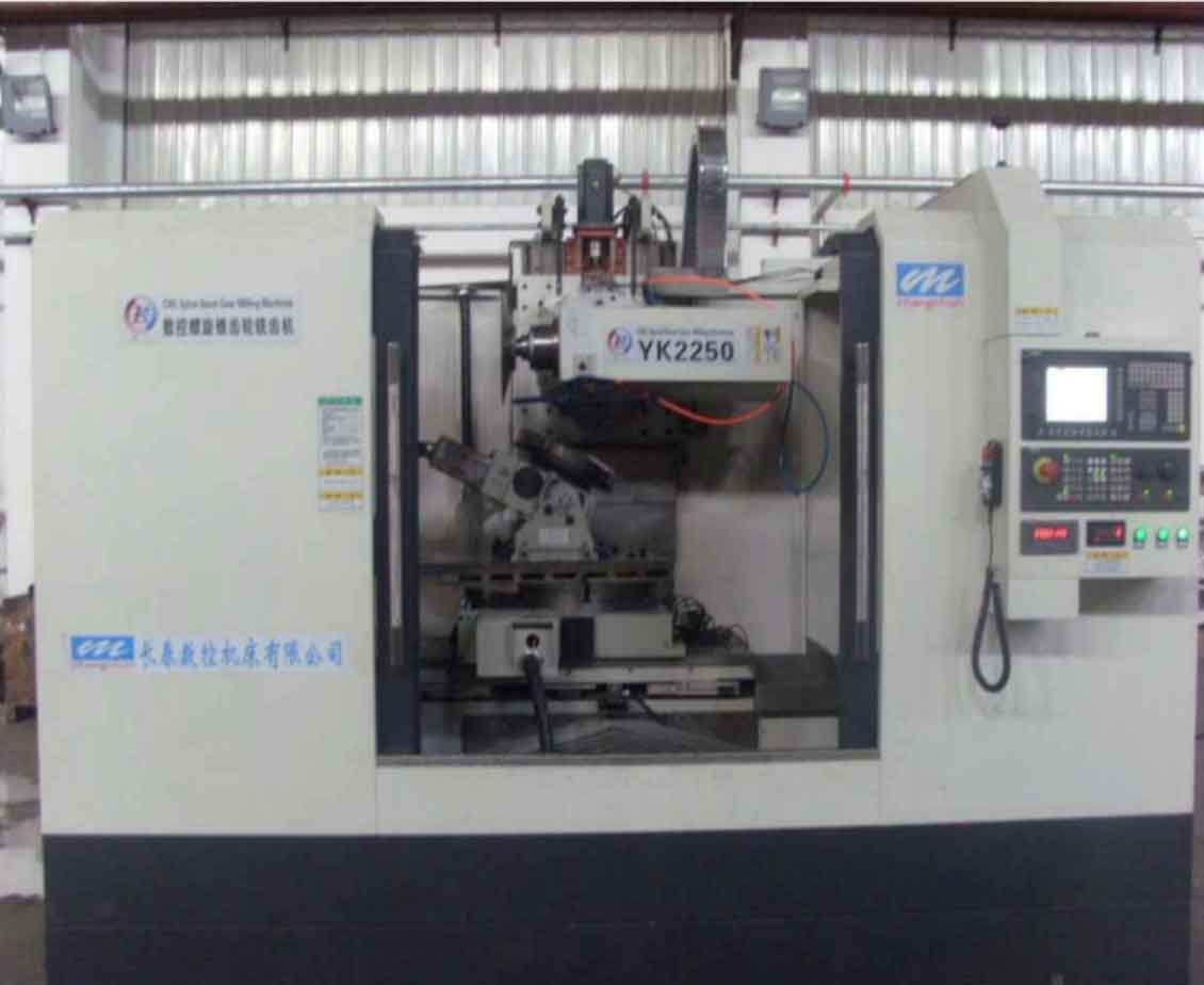
The image above illustrates a CNC spiral bevel gear milling machine, which exemplifies the advanced equipment used in modern gear milling processes. While my system focuses on cylindrical gears, the principles of parametric design and tooling are applicable across various gear milling applications, including bevel and spiral gears. By automating the modeling of gears and cutter heads, the system supports the preparation of digital data for such machines, reducing setup times and improving accuracy in gear milling operations.
Looking ahead, the parametric modeling system can be extended to include more complex gear types, such as bevel or worm gears, and integrate with CAM (Computer-Aided Manufacturing) software for direct toolpath generation in gear milling. Additionally, incorporating finite element analysis (FEA) for stress evaluation could further optimize gear designs for durability in gear milling applications. The use of cloud-based parameter libraries could also enhance collaboration among designers working on gear milling projects. Overall, this system represents a significant step toward digital transformation in gear manufacturing, where gear milling is a central process.
In conclusion, the development of a parametric modeling system for gear milling cutter heads based on SolidWorks secondary development has proven effective in automating the design of gears and their associated tools. By leveraging VB.Net and SolidWorks API, the system enables rapid parameterized modeling, reducing design time and errors for gear milling components. The integration of gear profile calculations, cutter head structural analysis, and user-friendly interface features provides a comprehensive solution for engineers involved in gear milling. With capabilities to handle diverse gear parameters and multiple cutter head specifications, the system promotes standardization and efficiency in gear milling workflows. As the industry moves toward increased automation, such parametric systems will play a crucial role in advancing gear milling technologies, ensuring precision and productivity in mechanical manufacturing.