
My exploration into the field of spiral bevel gear manufacturing begins with a fundamental understanding of the gear milling process, specifically the generative method. This principle is the cornerstone for machining these complex components, which are pivotal for transmitting motion and power between intersecting axes in applications ranging from automotive differentials to aerospace transmissions. The high load capacity, smooth operation, and low noise characteristics of spiral bevel gears make the precision of their gear milling a critical technological pursuit.
Generative Principle of Spiral Bevel Gear Milling
The core philosophy behind spiral bevel gear milling is the simulation of a meshing pair. In the gear milling machine, a mechanism called the “cradle” simulates an imaginary generating gear, known as the crown gear or generating gear. A rotating cutter head, mounted on this cradle, forms the cutting surface that represents a single tooth flank of this imaginary gear. The workpiece blank and this imaginary gear rotate synchronously about their respective axes with a precise ratio, dictated by their virtual tooth numbers. As this relative motion, or roll, occurs, the cutter head progressively generates the tooth flank on the blank. This method is the essence of generative gear milling. Upon completing one tooth slot, the cradle reverses to its start position, the workpiece retracts, indexes to the next tooth position, and the cycle repeats. The entire process is a meticulous application of generative gear milling theory.
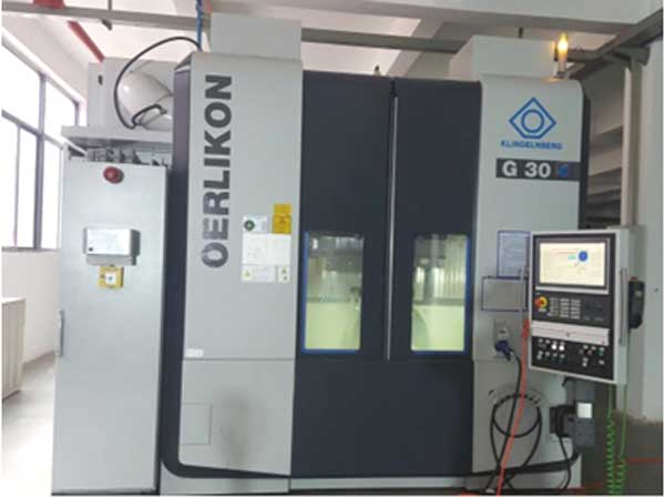
The advent of CNC technology has revolutionized this process. Modern CNC spiral bevel gear milling centers offer unparalleled flexibility and precision. They maintain the fundamental generative principle but replace complex mechanical gear trains with digitally controlled servo axes. This allows for sophisticated corrections and the machining of tooth geometries that were previously difficult or impossible to achieve with purely mechanical machines.
Mathematical Modeling for CNC Gear Milling
To translate the generative principle into actionable machine commands, a precise mathematical model of the gear milling system is indispensable. This model defines the spatial relationships between the cutter and the workpiece throughout the machining cycle. I establish coordinate systems centered on key machine components.
First, a static machine coordinate system $\Sigma_m \{O_m, X_m, Y_m, Z_m\}$ is defined, where $O_m$ is the machine center. The cradle coordinate system $\Sigma_c \{O_c, X_c, Y_c, Z_c\}$ is attached to the cradle, sharing its origin with $O_m$. The cutter coordinate system $\Sigma_k \{O_k, X_k, Y_k, Z_k\}$ is fixed to the cutter head. Finally, the workpiece coordinate system $\Sigma_w \{O_w, X_w, Y_w, Z_w\}$ is attached to the gear blank.
The kinematic chain describes how these systems move relative to each other during gear milling. The cradle rotates about the $Z_m$ axis by an angle $\varphi_c(t)$. Simultaneously, the workpiece rotates about its own axis $Z_w$ by an angle $\varphi_w(t)$. The fundamental relationship governing this motion is the roll ratio $i$, which relates the angular displacement of the workpiece to that of the cradle:
$$\varphi_w(t) = i \cdot \varphi_c(t)$$
The machine setup parameters position these coordinate systems relative to one another in their initial state. Key setup parameters include:
- Radial Distance ($S_k$): The distance from the cradle center $O_m$ to the cutter center $O_k$ in the machine plane.
- Angular Position ($q$): The angle between the line $O_mO_k$ and the $X_m$ axis.
- Machine Center to Back ($X_p$): The horizontal offset of the workpiece mounting point from the machine center.
- Sliding Base ($X_b$): The axial adjustment of the cutter head, controlling the depth of cut.
- Workpiece Tilt Angle ($\gamma_m$): The installation angle of the workpiece axis relative to the machine plane.
The transformation from the cutter system to the workpiece system can be expressed through a series of homogeneous transformation matrices, encompassing rotations and translations defined by these setup and motion parameters. This mathematical framework is the backbone of all subsequent calculations for CNC gear milling.
Calculation of Machine Settings for Gear Milling
The practical execution of gear milling requires the precise calculation of machine settings based on the gear design parameters. My analysis focuses on the calculations pertinent to face-milling using the Formate or “Fixed Setting” method for the gear member and the complementary generative method for the pinion, though the principles are broadly applicable.
Cutter Location Calculation
The cutter location defines where the cutter center must be positioned relative to the machine center. For a spiral bevel gear with a given mean cone distance $L_m$, mean spiral angle $\beta_m$, and nominal cutter radius $r_k$, the basic coordinates in the machine plane are derived from the geometry of the mean point. The vertical ($V$) and horizontal ($H$) coordinates are:
$$V = r_k \cos \beta_m$$
$$H = L_m – r_k \sin \beta_m$$
From these, the essential gear milling settings, radial distance $S_k$ and angular position $q$, are calculated:
$$S_k = \sqrt{V^2 + H^2}$$
$$q = \arctan\left(\frac{V}{H}\right)$$
On a mechanical machine, these settings $S_k$ and $q$ are achieved by adjusting an eccentric mechanism and rotating the cradle. The eccentric angle $\epsilon$ required to achieve the radial distance $S_k$ on a machine with eccentric linkage length $K$ is:
$$\epsilon = 2 \arcsin\left(\frac{S_k}{2K}\right)$$
The corresponding initial cradle angle $Q$ to set the angular position depends on the hand of the spiral. For a right-hand gear being cut:
$$Q = q – \frac{\epsilon}{2}$$
For a left-hand gear:
$$Q = q + \frac{\epsilon}{2}$$
Calculation of Motion Parameters for CNC Gear Milling
In CNC gear milling, the machine’s servo axes directly control the cradle rotation ($\varphi_c$) and workpiece rotation ($\varphi_w$). The primary task is to determine the total angular displacement for one tooth generation cycle. The basic roll ratio $i_g$ for generating is calculated from the number of teeth on the generated work gear $Z_w$ and the number of teeth on the imaginary crown gear $Z_c$:
$$i_g = \frac{Z_c}{Z_w}$$
The total cradle roll angle $\Phi_c$ for the generating stroke must be sufficient to fully generate the tooth flank. The corresponding workpiece rotation $\Phi_w$ during this stroke is:
$$\Phi_w = i_g \cdot \Phi_c$$
Indexing to the next tooth requires precise angular division. The theoretical index angle is $\theta_{index} = 360^\circ / Z_w$. Due to the finite resolution of the CNC system, this is often approximated by alternating between two closely spaced angles, $a$ and $b$, such that their average over the total number of teeth equals $360^\circ$. If $a$ is used $x$ times and $b$ is used $y$ times during the indexing of all $Z_w$ teeth, the following must hold:
$$x + y = Z_w$$
$$a \cdot x + b \cdot y = 360^\circ$$
Solving this system yields the pattern for distributing the index steps, minimizing cumulative error over the entire gear. This calculation is crucial for programming the CNC gear milling cycle.
Numerical Example and CNC Program Structure for Gear Milling
To solidify the theory, let’s consider a practical example of machining a spiral bevel gear. The gear pair parameters and the resulting calculated machine settings are summarized below.
| Parameter | Gear (Large) | Pinion (Small) |
|---|---|---|
| Number of Teeth | 38 | 7 |
| Module (mm) | 8.03 | |
| Spiral Angle | 35° | |
| Shaft Angle | 90° | |
| Hand of Spiral | Right | Left |
| Whole Depth (mm) | 12.69 |
| Machine Setting | Value |
|---|---|
| Radial Distance, $S_k$ (mm) | 124.97 |
| Angular Position, $q$ | 72.25° |
| Cradle Initial Angle, $Q$ | 52.90° |
| Work Installation Angle, $\gamma_m$ | 72.25° |
| Roll Ratio, $i_g$ | 1.017 |
| Cutter Diameter (mm) | 304.8 |
For the indexing calculation, assume the cradle generating roll $\Phi_c = 50.0^\circ$. The required workpiece rotation during generation is $\Phi_w = 1.017 \times 50.0^\circ = 50.85^\circ$. The nominal index angle is $360^\circ / 38 \approx 9.473684^\circ$. We can approximate this using two angles: $a = 9.473^\circ$ and $b = 9.474^\circ$. Solving the system:
$$x + y = 38$$
$$9.473x + 9.474y = 360$$
yields $x = 12$ and $y = 26$. This means in 38 indexing moves, angle $a$ is used 12 times and angle $b$ is used 26 times in a specific alternating pattern to ensure even distribution.
CNC Program Architecture
The CNC program for this gear milling operation is structured modularly. It typically consists of a main program that calls motion subroutines and a dedicated data section containing all geometric and kinematic parameters. The core machining cycle for one tooth includes:
- Approach: The workpiece advances to the full cutting depth position.
- Generating Roll: The cradle and workpiece rotate synchronously ($\varphi_c$ from $Q$ to $Q+\Phi_c$, $\varphi_w$ accordingly) while the cutter spins, generating the tooth flank.
- Return: The cradle rotates back to its start angle $Q$.
- Retract & Index: The workpiece retracts axially and then rotates by the designated index angle ($a$ or $b$).
This cycle is repeated 38 times, with the index angle following the predetermined sequence of 12 ‘a’s and 26 ‘b’s. The primary advantage of CNC gear milling is that changing to a different gear requires only modifying the parameter data block, while the core program logic remains unchanged, showcasing the flexibility and efficiency of digital manufacturing.
Conclusion
My detailed examination of spiral bevel gear milling traverses from its foundational generative theory to the implementation of modern CNC machining. The process hinges on accurately modeling the machine-workpiece-cutter system mathematically, which allows for the precise calculation of setup parameters like radial distance $S_k$ and angular position $q$, as well as motion parameters like roll ratio $i_g$ and indexed angles $a$ and $b$. The structured approach to CNC programming, separating logic from data, makes the gear milling process highly adaptable and precise. Mastery of these principles—the generative simulation, the coordinate transformations, the parametric calculations, and the structured programming—is essential for producing high-quality spiral bevel gears with the excellent surface finish, low noise, and high load capacity demanded by advanced mechanical systems. The transition from mechanical theory to digital execution encapsulates the evolution and enduring importance of precision gear milling.