
The transition from traditional wet machining to dry cutting for spiral bevel gears represents a significant advancement in gear manufacturing technology. This shift is driven by the notable advantages of dry cutting, which include superior surface finish quality, enhanced production efficiency, reduced energy consumption, and minimal environmental impact from cutting fluids. A fundamental aspect of mastering and optimizing this dry cutting process is the accurate prediction and analysis of cutting forces. Cutting forces are paramount as they directly influence machining power consumption, dimensional accuracy, surface integrity, tool wear, and the dynamic stability of the entire gear milling system. While prior research has established cutting force models for various gear machining processes like hobbing, form milling, and broaching, comprehensive models specifically for the complex generative gear milling of spiral bevel gears, which account for the intricate interactions of thermo-mechanical effects, remain less explored. This article focuses on developing and validating a robust milling force model for the rough cutting of spiral bevel pinions using the generative method, incorporating the effects of cutting temperature and material deformation.
The generative gear milling process for spiral bevel gears involves a complex, three-dimensional relative motion between the multi-blade face milling cutter (cutter head) and the gear blank. The instantaneous engagement condition, characterized by the undeformed chip geometry, is highly dynamic. A precise calculation of this geometry is the critical first step for force modeling. In the roughing operation, the cutter head and workpiece are in line contact. For a given instant (t), the instantaneous undeformed chip width, denoted as $$s(t)$$, is a function of the angular positions of both the cutter head $$\phi_p(t)$$ and the workpiece $$\phi_1(t)$$, derived from their spatial engagement relationship: $$s(t) = f(\phi_p(t), \phi_1(t))$$.
Simultaneously, the instantaneous undeformed chip thickness, $$t_h(t)$$, is primarily governed by the feed per tooth along the tooth length direction, $$f_z$$, and the rotational position $$\theta(t)$$ of the individual cutting insert on the cutter head. Given the significantly higher rotational speed of the cutter compared to the workpiece, the influence of workpiece rotation and tooth curvature on chip thickness is negligible. The thickness can thus be expressed as:
$$t_h(t) = f_z \cos \theta(t) + R – \sqrt{R^2 – [f_z \sin \theta(t)]^2}$$
where $$R$$ is the nominal radius of the cutter head. The feed per tooth $$f_z$$ is determined from the machine kinematics and gear geometry parameters, specifically the change in the surface parameter $$u$$ between successive tooth engagements, adjusted for the spiral angle $$\beta$$: $$f_z = (u_i – u_{i+1}) / \cos \beta$$.
The generated chip geometry is not a simple rectangular prism but approximates a tetrahedral shape due to the continuous relative motion. Analysis shows that the instantaneous undeformed chip width and thickness at successive moments during a single insert’s engagement are proportionally related:
$$\frac{t_{h}^{n-1}}{s^{\,n-1}} = \frac{t_{h}^{n}}{s^{\,n}} = \frac{t_{h}^{n+1}}{s^{\,n+1}}$$
This proportional relationship allows for the calculation of the chip width at non-measurement points based on the thickness, revealing that the maximum cutting force does not necessarily occur at the point of nominal contact but where the product of width and thickness is greatest.
The generative gear milling process is fundamentally an oblique cutting operation. The cutting edge is oriented at an inclination angle (oblique angle) relative to the direction of the cutting velocity vector. Therefore, the modeling framework is built upon oblique cutting theory. The key geometrical parameters in oblique cutting include the normal shear angle $$\phi_n$$, the normal rake angle $$\gamma_n$$, the inclination angle $$i$$, and the chip flow angle $$\eta_c$$. The normal shear angle is related to the chip thickness ratio:
$$\tan \phi_n = \frac{(t_h / t_c) \cos \gamma_n}{1 – (t_h / t_c) \sin \gamma_n}$$
where $$t_c$$ is the deformed chip thickness. According to Stabler’s rule, the chip flow angle is often approximated as equal to the inclination angle ($$\eta_c \approx i$$). The direction of material flow on the shear plane, defined by the shear flow angle $$\eta_s$$, is given by:
$$\tan \eta_s = \frac{\tan i \cos(\phi_n – \gamma_n) – \tan \eta_c \sin \phi_n}{\cos \gamma_n}$$
The core of the force model lies in calculating the shear force on the primary shear plane. For an oblique cut with a triangular chip cross-section (as in face milling), the shear force $$F_s$$ for an outer blade is:
$$F_{so} = \frac{\tau_{so} s_o t_h}{2 \cos i_o \sin \phi_{no}}$$
where $$s_o$$ is the instantaneous chip width for the outer blade, $$i_o$$ is its inclination angle, $$\phi_{no}$$ is its normal shear angle, and $$\tau_{so}$$ is the material’s flow stress in the shear zone.
To account for the strain, strain-rate, and temperature sensitivity of the workpiece material (typically alloy steel), the Johnson-Cook constitutive model is employed to determine $$\tau$$:
$$\tau = \frac{1}{\sqrt{3}} \left[ A + B \left( \frac{\gamma}{\sqrt{3}} \right)^n \right] \left[ 1 + C \ln\left(\frac{\dot{\gamma}}{\dot{\gamma}_0}\right) \right] \left[ 1 – \left( \frac{T – T_r}{T_m – T_r} \right)^m \right]$$
where:
- $$A, B, C, n, m$$ are material constants,
- $$\gamma$$ and $$\dot{\gamma}$$ are the effective strain and strain rate,
- $$\dot{\gamma}_0$$ is a reference strain rate,
- $$T$$ is the current temperature in the shear zone,
- $$T_r$$ is the room temperature, and
- $$T_m$$ is the melting temperature of the workpiece material.
This equation integrates the effects of work hardening, strain-rate hardening, and thermal softening, which are crucial for accurate force prediction across a range of cutting speeds.
The normal force on the shear plane, $$F_n$$, is found from the shear force using the force balance relationships on the chip, involving the friction angle $$\beta$$:
$$F_{no} = \frac{\cos \eta_{so} [ \tan(\phi_{no} – \gamma_{no}) + \tan \beta_o \cos \eta_{co} ]}{1 – \tan \beta_o \cos \eta_{co} \tan(\phi_{no} – \gamma_{no})} F_{so}$$
The friction angle $$\beta_o$$ can be related to the shear angle through the Merchant equation: $$\phi_{no} = \frac{\pi}{4} – \frac{\beta_o}{2} + \frac{\gamma_{no}}{2}$$.
Finally, the three orthogonal cutting force components on the outer blade (tangential $$F_c$$, radial $$F_r$$, axial $$F_a$$) are resolved from the shear plane forces via a transformation matrix:
$$
\begin{bmatrix}
F_{co} \\
F_{ro} \\
F_{ao}
\end{bmatrix}
=
\begin{bmatrix}
\cos \eta_{so} \cos \phi_{no} \cos i_o + \sin \eta_{so} \sin i_o & -\cos \eta_{so} \sin \phi_{no} \\
\cos \eta_{so} \cos \phi_{no} \sin i_o – \sin \eta_{so} \cos i_o & \sin \phi_{no} \sin i_o \\
\sin \phi_{no} \cos i_o & \cos \phi_{no}
\end{bmatrix}
\begin{bmatrix}
F_{so} \\
F_{no}
\end{bmatrix}
$$
These force components are then transformed from the tool coordinate system to the machine coordinate system (X, Y, Z) by a rotation based on the angular position of the outer blade $$\Phi_o$$:
$$
\begin{bmatrix}
F_{xo} \\
F_{yo} \\
F_{zo}
\end{bmatrix}
=
\begin{bmatrix}
-\cos \Phi_o & \sin \Phi_o & 0 \\
\sin \Phi_o & \cos \Phi_o & 0 \\
0 & 0 & 1
\end{bmatrix}
\begin{bmatrix}
F_{co} \\
F_{ro} \\
F_{ao}
\end{bmatrix}
$$
An identical set of calculations is performed for the inner blade of the cutter head, considering its distinct pressure and inclination angles. The angular position of the inner blade $$\Phi_i$$ is offset from the outer blade by $$\Phi_o – \Phi_i = 2\pi / N$$, where $$N$$ is the total number of blades. Assuming only one pair of blades (one inner, one outer) is engaged at any time, the total dynamic cutting forces acting on the workpiece in the machine coordinate system are the vector sum of the inner and outer blade forces:
$$F_x = F_{xi} + F_{xo}, \quad F_y = F_{yi} – F_{yo}, \quad F_z = F_{zi} + F_{zo}$$.
A comprehensive simulation program was developed in MATLAB to implement this gear milling force model. The program flow involves inputting gear geometry, cutter parameters, material properties, and machining conditions, calculating the instantaneous chip geometry and thermomechanical state, solving for the forces using the oblique cutting model, and outputting the time-varying force signals. Key parameters used for simulation are listed below:
| Parameter | Value |
|---|---|
| Number of Teeth | 17 |
| Module | 10.36 mm |
| Face Width | 50.00 mm |
| Hand of Spiral | Left |
| Mean Spiral Angle | 35.0° |
| Pressure Angle | 20.0° |
| Face Cone Angle | 35.75° |
| Parameter | Value |
|---|---|
| Cutter Head Radius (R) | 152.4 mm |
| Number of Blades (N) | 16 (8 inner, 8 outer) |
| Outer Blade Pressure Angle | 18.0° |
| Inner Blade Pressure Angle | 22.0° |
| Workpiece Material | AISI 1045 Steel |
| Johnson-Cook Constants (A, B, n, C, m) | 507 MPa, 320 MPa, 0.28, 0.064, 1.06 |
The simulation analyzed the influence of key gear milling parameters. First, the effect of cutting speed (Vc) was investigated at a constant feed rate. The results, plotting the maximum resultant force against cutting speed, revealed a non-linear relationship. The force initially increased with speed, peaking around 70 m/min, after which it gradually decreased. This trend is a direct consequence of the competing effects captured in the Johnson-Cook model: strain-rate hardening dominates at lower speeds, increasing stress, while thermal softening becomes increasingly significant at higher speeds, reducing the flow stress.
Second, the effect of feed rate was analyzed at a constant cutting speed of 70 m/min. The simulation showed a strong, approximately linear correlation between the maximum cutting force components (Fx, Fy, Fz) and the feed per tooth. This is expected as feed directly increases the uncut chip area, which is the primary geometric determinant of the force magnitude in the model.
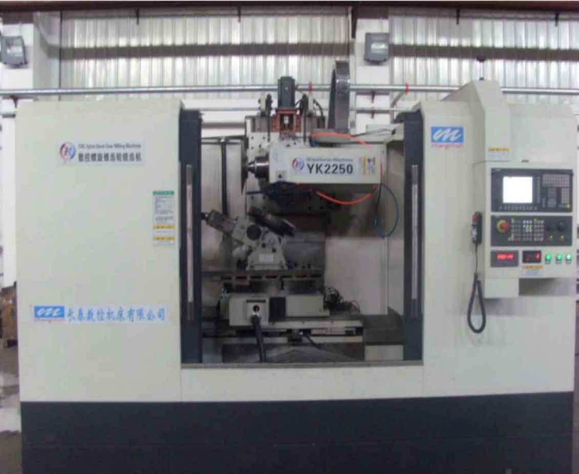
To validate the proposed gear milling force model, practical cutting tests were conducted on a modern CNC spiral bevel gear milling machine (YK2260DX). The machine’s Siemens 828D CNC system provides real-time monitoring of the servo motor torques for the cutter spindle, workpiece spindle, and all linear axes. During dry roughing of pinions, the instantaneous torque data for the X, Y, and Z axes were recorded. The net torque due to cutting was obtained by subtracting the idle-running torque from the recorded values. These torques were then converted to cutting forces using the machine’s ball-screw leads.
The experimental study on the effect of cutting speed showed a trend consistent with the simulation. The cutting forces increased from 60 to 70 m/min, showed a slight decrease at 80 m/min, and a minor increase again at 90 m/min. The close match around the 70 m/min peak validates the model’s ability to capture the thermomechanical transition. The deviation at 90 m/min can be attributed to factors like increased tool wear, which is not explicitly included in the current model.
| Parameter Varied | Simulation Trend | Experimental Trend | Agreement |
|---|---|---|---|
| Cutting Speed (Vc) | Peak force at ~70 m/min, then decrease. | Peak force between 70-80 m/min, complex behavior at highest speed. | Good agreement around the critical speed; model captures key thermo-mechanical effect. |
| Feed per Tooth (fz) | Strong, near-linear increase in force with feed. | Clear increasing trend with feed, though not perfectly linear due to system dynamics. | Very good agreement in the overall trend and sensitivity. |
The feed rate tests confirmed the predicted strong positive correlation. The measured cutting forces in the X, Y, and Z axes consistently increased with higher feed rates. While the experimental relationship exhibited some non-linearity likely due to machine dynamics, deflection, and minor runout, the fundamental trend aligned excellently with the simulation, confirming the model’s accuracy in predicting the force response to changes in chip load.
In conclusion, this research has successfully developed a mechanistic milling force model for the generative rough gear milling of spiral bevel gears. The model integrates a precise calculation of the instantaneous undeformed chip geometry with the principles of oblique cutting theory and a temperature-sensitive material constitutive law. The implementation of this model in a simulation environment allows for the analysis of cutting force behavior under varying process parameters, providing valuable insights for process optimization in dry gear milling applications. The validation through practical cutting tests, utilizing advanced machine tool monitoring capabilities, demonstrates the model’s effectiveness and accuracy. This model serves as a foundational tool for predicting machining loads, optimizing cutting parameters to reduce tool wear and improve surface quality, and enhancing the stability and efficiency of the spiral bevel gear milling process. Future work may focus on integrating tool wear progression and a more detailed thermal model to further extend the predictive capability across the entire tool life.