
In my practice within high-precision manufacturing, the gear milling of aeronautical spiral bevel gears stands as a cornerstone process. These components are critical for power transmission, speed reduction, and directional change in systems such as engine gearboxes and helicopter main transmissions. The quality of the milled tooth form directly dictates the performance of final hardened and ground gears concerning load capacity, service life, transmission efficiency, vibration, and noise. This process is strategically positioned after semi-finishing of the gear blank and before heat treatment, serving as the foundational geometry for subsequent finishing operations. My objective is to delineate a systematic, forward-looking design and verification framework for the gear milling operation, structured around the V-model of systems engineering. This approach moves beyond traditional resource-oriented planning and equips process engineers with a holistic, phase-gated methodology essential for robust digital transformation and new product development.
1. Architectural Framework: Applying the V-Model to Gear Milling Process Design
I conceptualize the gear milling process design as a self-contained system. The V-model provides an excellent scaffold, aligning traditional process development stages with systematic engineering phases and their corresponding verification activities.
On the left branch of the V-model, the design activities progress from high-level requirements to detailed specifications. On the right branch, verification activities ascend from component testing to system validation. For gear milling, this translates as follows:
- Requirements Analysis & System Verification: Corresponds to understanding the needs of the subsequent finishing (grinding) operation and the final product performance.
- Preliminary Design & Integration Testing: Aligns with defining the static technical states of the workpiece, tool, and machine, and testing their integrated performance (e.g., trial cuts and contact pattern checks).
- Detailed Design & Unit Testing: Involves calculating the precise kinematic relationships between machine axes, tool paths, and workpiece, and verifying individual elements like cutter geometry and NC programs.
The ultimate deliverable of this system is not merely a process sheet; it is a comprehensive gear milling solution package encompassing the documented process specification, operating procedures, standard work instructions (SOPs), the calculation and simulation models from specialized gear software, and the final machine tool NC programs and inspection routines.
| V-Model Phase | Process Design Activity | Primary Outputs | Verification & Validation Activity |
|---|---|---|---|
| Requirements | Analyze grinding requirements, heat treat constraints, and lean manufacturing needs. | Gear Milling Requirements Specification (target tooth form, stock allowances, interface requirements). | Validate against final gear design and subsystem performance models. |
| Preliminary Design | Define gear blank geometry, theoretical tooth geometry, and select machine/tool/fixture concepts. | Preliminary Gear Data Sheet, Machine/Tool Selection Rationale. | Static interference checks, theoretical Tooth Contact Analysis (TCA), measurement of blank dimensions. |
| Detailed Design | Calculate full machine settings (kinematics), generate cutter path data, define setup and cutting parameters. | Machine Setting Sheet, NC Program, Cutter Design Drawing, Setup & Cutting Parameter Sheet. | Simulation in gear software, trial cut and contact pattern check, dimensional verification of first article. |
| Implementation | Execute the milling process on the production machine. | Milled Gear. | In-process and post-process inspection (dimensions, surface finish, contact pattern). |
2. Detailed Design and Verification Stages for Gear Milling
2.1 Requirements Analysis and Validation
The fundamental requirement for the gear milling operation is to produce a tooth form that, after heat treatment and grinding, will yield the specified final gear performance. This cascades down into specific, verifiable requirements for the milled pre-form.
- Geometric Stock Allowance: The milled tooth surfaces must leave a precise and uniform stock layer for the subsequent grinding operation. This allowance is not constant; it must compensate for heat treatment distortions and be optimized across the tooth profile (flank) and root fillet. The required stock $$ S(\theta, R) $$ is a function of the polar coordinates on the tooth surface and is determined through empirical data and simulation.
- Pre-Form Contact Pattern: While the final contact pattern is achieved in grinding, the milled gear pair should exhibit a contact pattern that is correctly located and has a basic shape and trend conducive to final adjustment. Verification is performed by running a trial assembly (with adjusted mounting distance and reduced backlash) with its mate on a gear testing machine.
- Edge Condition and Burr Control: The gear milling process must control burrs and sharp edges at the tooth ends and root transitions. This is critical because heat-treated surfaces are brittle, and subsequent handling or grinding could cause spalling if sharp edges are present.
- Surface Integrity: The milling process must generate a surface free of tears, excessive burns, or micro-cracks that could serve as stress risers after heat treatment. This is validated through metallographic examination of sample parts.
The validation at this level relies heavily on digital models. Specialized gear software (e.g., Gleason GEMS, Klingelnberg KIMOS) is used to model the theoretical milled tooth form and compare it against the nominal ground tooth form, ensuring stock allowances are met. This digital verification complements the physical trial assembly check.
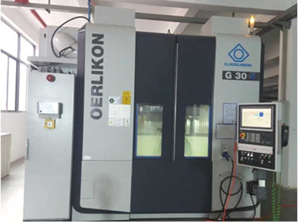
2.2 Preliminary Design and Integration Testing
In this phase, I establish the static technical parameters for all elements involved in the gear milling system.
2.2.1 Gear Blank and Theoretical Tooth Geometry Calculation
The gear blank dimensions are not merely the nominal drawing values. Tolerances must be considered, especially for locating diameters and faces used for clamping during gear milling and grinding. For example, the mounting distance $$ A $$ has a tolerance $$ \pm t_A $$. The worst-case scenario must be analyzed to ensure the cutter path does not interfere with the gear body or fixture. Key blank parameters include:
- Pitch Cone Distance (Crown-to-Apex): $$ R = \frac{m_t \cdot z}{2 \sin \delta} $$, where $$ m_t $$ is transverse module, $$ z $$ is number of teeth, and $$ \delta $$ is pitch angle.
- Face Width: $$ b $$, typically limited to $$ b \leq R/3 $$ and $$ b \leq 10m $$ to avoid undercut at the toe.
- Root Angle: $$ \delta_f $$, critical for checking cutter interference.
The drawing often provides only basic tooth data (number of teeth, module, pressure angle). A complete set of geometrical parameters for manufacturing must be calculated using gear handbook methods or software. This includes:
$$ \text{Chordal Tooth Thickness: } \bar{s} = s – \frac{s^3}{24r^2} $$
$$ \text{Chordal Addendum: } \bar{h_a} = h_a + \frac{s^2 \cos \delta}{8r} $$
where $$ s $$ is circular tooth thickness at the measurement point, $$ r $$ is the back cone distance, and $$ h_a $$ is the addendum.
2.2.2 Machine, Tool, and Fixture Concept Selection
The selection is based on the calculated geometry and production volume.
| Element | Key Selection Parameters | Design Considerations for Gear Milling |
|---|---|---|
| Machine Tool | Maximum workpiece diameter/swing, axis travel, spindle power/rigidity, CNC capability. | Must accommodate the gear blank and provide necessary axes for the chosen milling method (e.g., 6-axis for continuous indexing). |
| Cutter Head | Cutter diameter, number of blade groups, blade profile (modifiable for topology). | Selected based on module, tooth depth, and desired tooth form (Gleason, Klingelnberg, or Oerlikon system). Must generate the required root fillet. |
| Workholding Fixture | Clamping mechanism, locating surfaces, stiffness, compatibility with machine table. | Must use stable, precise datums from the gear blank. Must avoid deflection under cutting forces to maintain tooth spacing accuracy. |
Digital TCA (Tooth Contact Analysis) at this stage is invaluable. By simulating the contact of the theoretical milled tooth forms (including stock) in software, I can assess and optimize the contact pattern location and motion transmission characteristics before any metal is cut.
2.3 Detailed Design and Unit Testing
Here, I define the precise dynamic relationships between the workpiece, the rotating cutter, and the moving machine axes—the core of gear milling kinematics.
2.3.1 Machine Setting Calculation (Kinematics)
The fundamental formula governing the generation of a spiral bevel gear tooth surface during gear milling relates the workpiece rotation to the cradle rotation (or its CNC equivalent). For a traditional mechanical machine setup, the ratio is given by the machine constant or ratio of roll:
$$ R_{oll} = \frac{\text{Workpiece Rotation}}{\text{Cradle Rotation}} = \frac{N_c}{N_w} $$
where $$ N_c $$ is the number of cutter head blades and $$ N_w $$ is the number of gear teeth for single indexing methods. In modern CNC gear milling, this is simulated by synchronized axis movements. The complete set of machine settings includes:
- Machine Center to Back: $$ X $$
– Sliding Base: $$ X_B $$
– Blank Offset: $$ E $$
– Cradle Angle: $$ q $$
– Tilt Angle: $$ i $$
– Swivel Angle: $$ j $$
The calculation of these settings is traditionally done via “milling data sheets” or, more efficiently, by dedicated gear software. The software uses the defined machine kinematics model to calculate the tool path required to generate the designed tooth flank.
2.3.2 Cutting Parameter Definition
Parameters are selected to balance productivity, tool life, and surface integrity. Key formulas include:
$$ \text{Cutting Speed: } v_c = \frac{\pi \cdot D_c \cdot n_c}{1000} \quad \text{(m/min)} $$
$$ \text{Feed per Tooth: } f_z = \frac{v_f}{z_c \cdot n_c} \quad \text{(mm/tooth)} $$
$$ \text{Metal Removal Rate: } Q = a_e \cdot a_p \cdot v_f \quad \text{(cm³/min)} $$
where:
– $$ D_c $$ = Cutter Diameter (mm)
– $$ n_c $$ = Cutter Spindle Speed (rpm)
– $$ v_f $$ = Feed Rate (mm/min)
– $$ z_c $$ = Number of Cutter Blades (effective)
– $$ a_e $$ = Radial Depth of Cut (mm)
– $$ a_p $$ = Axial Depth of Cut (mm)
2.3.3 Verification through Simulation and Trial
Before production, the detailed design is rigorously verified:
- Digital Simulation: The NC program is simulated within the gear software or a machine-specific CAM package to check for collisions and verify the generated tooth surface against the theoretical model. The software calculates and visually confirms the applied stock allowance and root fillet geometry.
- Trial Cut and Contact Pattern Check: A first article is machined, often with intentional tooth thickness reduction for easy assembly. It is paired with its mating gear, and the contact pattern is examined on a testing machine. The pattern’s location, size, and shape are compared to the software prediction. Adjustments are made iteratively, typically starting with basic machine settings (E, X, q) before moving to more complex corrections (modified roll).
- Dimensional Inspection: The trial gear is measured on a gear measuring center or with specialized gauges to verify tooth thickness, spacing, runout, and profile.
| Verification Target | Method/Tool | Acceptance Criteria |
|---|---|---|
| Tooth Flank Geometry & Stock | Gear Measuring Center (GMM) vs. CAD/Software Model | Deviation within specified pre-grind stock envelope. No undercut or overcut. |
| Contact Pattern Location | Physical Roll Test on Testing Machine | Pattern centered or slightly biased as planned. Correct length and width trend. |
| Cutting Process Stability | In-process monitoring (power, vibration), Post-process surface inspection | Stable signals, absence of chatter marks, burns, or excessive burrs. |
| Tool Path & Collision | CNC Path Simulation Software | No collisions between tool, holder, workpiece, or fixture. |
3. Integration and Digital Thread for Advanced Gear Milling
The ultimate goal of this structured approach is to create a seamless digital thread for gear milling process development. By formalizing each stage of the V-model, the resulting data, models, and knowledge become structured assets.
- Standardized Calculation Kernels: Developing or configuring software with standardized algorithms for gear geometry, kinematics, and TCA that align with both international standards (AGMA, ISO) and company-specific manufacturing practices.
- Unified Gear Database: Creating a central repository that contains not just product design data, but also manufacturing resource attributes—machine capabilities, standard cutter libraries, fixture models, and historical process parameters. This database feeds directly into the process design software.
- Automated Solution Generation: With a robust model, the system can automatically generate optimized machine settings, cutter designs (for modifiable blades), and NC programs for a given gear design, dramatically reducing lead time for new product introduction.
- Closed-Loop Optimization: Post-production inspection data (from GMMs) is fed back into the digital model. Data analytics and machine learning can then be applied to correlate process parameters with final gear quality, enabling continuous refinement of the gear milling solution.
This forward-looking, model-based methodology transforms gear milling from a craft-dependent operation into a predictable, optimized, and digitally integrated manufacturing system. It ensures that the critical tooth pre-form is not just machined, but is scientifically designed and verified to be the perfect foundation for a high-performance aerospace transmission component.