
In the realm of gear manufacturing, the process of form milling for straight bevel gears remains a critical technique, particularly in scenarios involving small batches or limited access to specialized equipment. As I delve into this topic, I aim to address prevalent misconceptions and inaccuracies in existing literature regarding gear milling practices. Through this discussion, I will explore the intricacies of cutter design, cutting methods, and parameter calculations, all from my firsthand perspective, to enhance the accuracy and efficiency of gear milling operations. The keyword ‘gear milling’ will be frequently emphasized, as it is central to understanding and improving these processes.
The theoretical foundation of straight bevel gears involves spherical involute tooth profiles, where the tooth shape and thickness vary along the tooth length. This complexity makes gear milling more challenging compared to cylindrical gears. In my experience, many factories rely on form milling due to its simplicity in tooling, machine, and fixture requirements. However, I have observed that numerous guides on gear milling confuse different cutting methods and cutter tooth profiles, leading to subpar gear quality. Therefore, I believe it is essential to clarify these aspects to ensure successful gear milling outcomes.
When performing gear milling for straight bevel gears, various cutting methods exist, but each necessitates a specific cutter tooth profile. The standard bevel gear milling cutters commonly produced are designed based on the tooth curve at the gear’s large end. These cutters are typically marked with a distinct symbol, indicating their intended use. In my analysis, I find that using these cutters with incorrect cutting methods—such as rotating the workpiece around an axis perpendicular to the milling machine table—introduces significant errors. Instead, the proper gear milling method involves offsetting the workpiece laterally by a distance S and rotating it around its own axis by an angle ω to sequentially finish both tooth flanks. This approach aligns with the cutter design and minimizes deviations in tooth form.
To elaborate, the correct gear milling procedure begins with rough milling the tooth slots after centering the workpiece with the cutter. Then, the milling machine’s transverse table is moved to offset the workpiece by a distance S along the cutter axis. Subsequently, the workpiece is rotated by an angle ω using a dividing head, bringing one tooth flank into contact with the cutter for finishing. After finishing all teeth on one side, the workpiece is offset in the opposite direction by 2S and rotated by 2ω in reverse to finish the other flanks. Throughout this gear milling process, the rotation angle ω should be adjusted based on the semi-value of the large-end tooth thickness allowance. This method, in my view, ensures that the cutter tooth profile correctly engages with the gear tooth curve, thereby improving accuracy.
The offset amount S is a pivotal parameter in gear milling, as it determines the relative position between the cutter and workpiece. Based on the design principles of standard cutters, I propose that S should be calculated using the following formula derived from the cutter’s tooth curve geometry:
$$ S = \frac{T}{2} – Y m_0 $$
Here, T represents the actual tooth thickness of the cutter measured at a distance of 1.2m0 from the tooth tip, m0 is the cutter module, and Y is the offset coefficient. The coefficient Y depends on the cutter’s design parameters, specifically the virtual tooth number z_v and the angle λ. From geometric relationships, Y can be expressed as:
$$ Y = \frac{z_v}{2} \sin\left(\frac{90^\circ}{z_v} – \lambda\right) $$
This formulation ensures that during gear milling, the cutter tooth profile aligns with the intended curve position at the gear’s large end, preserving tooth form accuracy. To facilitate practical applications, I have compiled a table of offset coefficients Y for standard cutter numbers, applicable for modules ranging from 0.3 to 10 mm. This table summarizes key data for gear milling practitioners:
| Cutter Number | λ (angle in degrees and minutes) | Y (offset coefficient) |
|---|---|---|
| 1 | 3°44′ | 0.3942 |
| 2 | 3°14′ | 0.3902 |
| 3 | 2°40′ | 0.3897 |
| 4 | 2°12′ | 0.3821 |
| 5 | 1°47′ | 0.3807 |
| 6 | 1°21′ | 0.3730 |
| 7 | 0°52′ | 0.3694 |
| 8 | 0°22′ | 0.3534 |
In gear milling, it is important to note that the offset S should not vary with the gear’s tooth width coefficient (φ_R = b/R, where b is face width and R is cone distance). The λ values in the table are based on φ_R = 1/3, but the cutter design ensures that the tooth curve position remains consistent regardless of φ_R changes. Altering S based on φ_R, as suggested in some sources, can lead to inaccuracies at the large end, compromising gear milling quality. I have verified that miscalculations of S—such as those derived from assuming the tooth line passes through the pitch cone apex—result in oversized offsets, which distort the large-end tooth form and exacerbate small-end tip thickness errors. Conversely, methods that reduce S to thin the small-end tooth thickness weaken tooth strength and impair contact precision. Thus, adhering to the above formula is crucial for effective gear milling.
Another critical aspect in gear milling is the workpiece installation angle δ_f, often referred to as the cutting angle. This angle ensures that the tooth slot bottom is parallel to the milling machine table during gear milling. Many guidelines incorrectly set δ_f as the root cone angle that intersects the pitch cone apex. However, for standard cutters designed with uniform radial clearance of 0.2m (where m is the large-end module), the actual root cone does not pass through the apex. Therefore, I recommend calculating δ_f using the following equation:
$$ δ_f = δ – \arctan\left(\frac{m}{R}\right) $$
Here, δ is the gear’s pitch cone angle. This adjustment accounts for the design specifics of the cutter, preventing errors where the tooth slot depth decreases from the large end to the small end. In my gear milling experiments, using an incorrect installation angle leads to insufficient cutting depth at the small end, contributing to increased tip thickness and reduced accuracy. By applying this formula, gear milling operators can achieve proper slot depths and enhance overall gear quality.
The issue of increased tooth tip thickness at the small end is inherent in form milling due to the cutter being designed for the large-end tooth form. However, through careful gear milling parameter adjustments, this can be mitigated. Standard cutters are designed to minimize small-end tooth form errors, and with correct offset S and installation angle δ_f, the small-end tip thickness often remains within acceptable limits without manual filing. Nevertheless, for gears with small pitch cone angles and low tooth numbers, the small-end tooth form error may be more pronounced, causing excessive tip thickening. In such cases, I have found that increasing the addendum angle θ_a to reduce the small-end addendum height effectively controls tip thickness. This approach, compared to thinning the tooth thickness, has less impact on gear meshing smoothness and load capacity. The relationship can be expressed through the addendum modification factor in gear milling:
$$ \Delta h_a = h_a \cdot \tan(\theta_a) $$
where Δh_a is the reduction in addendum height at the small end, and h_a is the nominal addendum. By optimizing θ_a, gear milling processes can avoid tedious manual corrections and maintain tooth strength, thereby improving the efficiency and quality of gear milling operations.
In modern gear milling, advanced machinery plays a significant role in achieving high precision. For instance, specialized gear milling machines offer enhanced control over parameters like offset and rotation. Below is an example of such equipment, which can be integrated into gear milling workflows to boost accuracy:
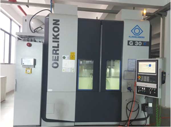
Utilizing such machines in conjunction with correct gear milling parameters—such as S, ω, and δ_f—can significantly reduce errors and streamline production. In my view, investing in appropriate technology complements the methodological refinements discussed here, making gear milling more reliable for straight bevel gears.
To further illustrate the gear milling process, I will summarize key formulas and parameters in a comprehensive table. This table encapsulates the essential calculations for successful gear milling, serving as a quick reference for practitioners:
| Parameter | Symbol | Formula or Description | Role in Gear Milling |
|---|---|---|---|
| Offset Amount | S | $$ S = \frac{T}{2} – Y m_0 $$ | Positions cutter for accurate large-end tooth form |
| Offset Coefficient | Y | $$ Y = \frac{z_v}{2} \sin\left(\frac{90^\circ}{z_v} – \lambda\right) $$ | Derived from cutter design; ensures consistency |
| Cutter Tooth Thickness | T | Measured at 1.2m0 from tooth tip | Input for offset calculation |
| Workpiece Rotation Angle | ω | Adjusted based on large-end tooth thickness allowance | Facilitates finishing of tooth flanks |
| Installation Angle | δ_f | $$ δ_f = δ – \arctan\left(\frac{m}{R}\right) $$ | Ensures tooth slot bottom parallelism |
| Pitch Cone Angle | δ | Gear design parameter | Base for installation angle calculation |
| Cone Distance | R | $$ R = \frac{m z}{2 \sin δ} $$ for straight bevel gears | Influences installation angle and tooth geometry |
| Addendum Modification | θ_a | Increased to reduce small-end addendum height | Controls small-end tip thickness |
In addition to these parameters, I emphasize that gear milling requires meticulous setup and verification. For example, the offset S should be measured and adjusted using precision instruments to avoid cumulative errors. During gear milling, it is advisable to perform trial cuts on sample materials to validate parameters before full-scale production. This iterative approach, combined with the formulas above, enhances the reliability of gear milling outcomes.
Moreover, the interaction between cutter wear and gear milling accuracy cannot be overlooked. As cutters degrade over time, tooth profiles may deviate, affecting S and Y values. Regular inspection and maintenance of cutters are essential for sustained gear milling quality. I recommend monitoring cutter condition and recalculating parameters periodically, especially in high-volume gear milling applications. This proactive stance aligns with best practices in manufacturing, where consistency is key to producing durable and precise gears.
From a broader perspective, the evolution of gear milling technology continues to offer new possibilities. Computer numerical control (CNC) systems, for instance, allow for automated adjustments of offset and rotation, reducing human error in gear milling. Integrating the corrected methodologies discussed here into CNC programming can further optimize processes. In my exploration, I have seen that software simulations of gear milling can predict tooth form errors and suggest parameter tweaks, thereby refining real-world operations. Embracing such advancements ensures that gear milling remains a viable and efficient method for straight bevel gear production, even as industry demands grow.
In conclusion, the form milling of straight bevel gears is a nuanced process that demands a deep understanding of cutter design and cutting methods. Through my analysis, I have highlighted the importance of using standard cutters with the correct offset S, installation angle δ_f, and other parameters to achieve accurate gear profiles. By addressing common errors and providing clear formulas and tables, this discussion aims to empower gear milling practitioners to improve their techniques. I encourage continuous learning and adaptation in gear milling practices, as even small refinements can lead to significant enhancements in gear quality and performance. As industries seek cost-effective solutions for small-batch production, mastering gear milling will remain invaluable, ensuring that straight bevel gears meet the rigorous standards of modern machinery and transmission systems.