
In the automotive industry, the steering system is a critical component that ensures vehicle safety and maneuverability. As an engineer focused on vehicle design, I have extensively studied and implemented rack and pinion steering systems for passenger cars. This system, known for its simplicity and efficiency, relies on the precise interaction between a gear (the pinion) and a linear rack to convert rotational motion from the steering wheel into lateral movement that turns the wheels. In this article, I will delve into the comprehensive design process of a rack and pinion gear system, covering structural analysis, parameter determination, and detailed calculations to ensure robustness and safety. The rack and pinion gear mechanism is favored in modern passenger cars due to its compact design and direct feedback, but it requires meticulous engineering to handle varied loads and conditions. Throughout this discussion, I will emphasize the importance of the rack and pinion gear in achieving reliable steering performance, and I will incorporate tables and formulas to summarize key aspects. By sharing my insights, I aim to provide a valuable resource for fellow designers and engineers working on similar projects.
The rack and pinion steering system consists of several interconnected components that work together to translate driver input into wheel movement. At its core, the rack and pinion gear assembly includes a pinion gear attached to the steering column and a rack that engages with it. When the steering wheel is turned, the pinion rotates, causing the rack to move laterally. This motion is then transferred to the tie rods and steering knuckles, which pivot the wheels. The entire assembly is housed in a lightweight casing, often made from aluminum or magnesium alloys to reduce mass. One key advantage of the rack and pinion gear system is its minimal play, which is maintained through a spring-loaded mechanism that presses the rack against the pinion to eliminate backlash. However, this design also introduces challenges, such as susceptibility to road feedback or “kickback,” which can cause driver fatigue over long drives. To address this, designers must carefully balance reversibility and damping in the rack and pinion gear setup. In my experience, optimizing the geometry and material selection for the rack and pinion gear is essential for enhancing durability and comfort.
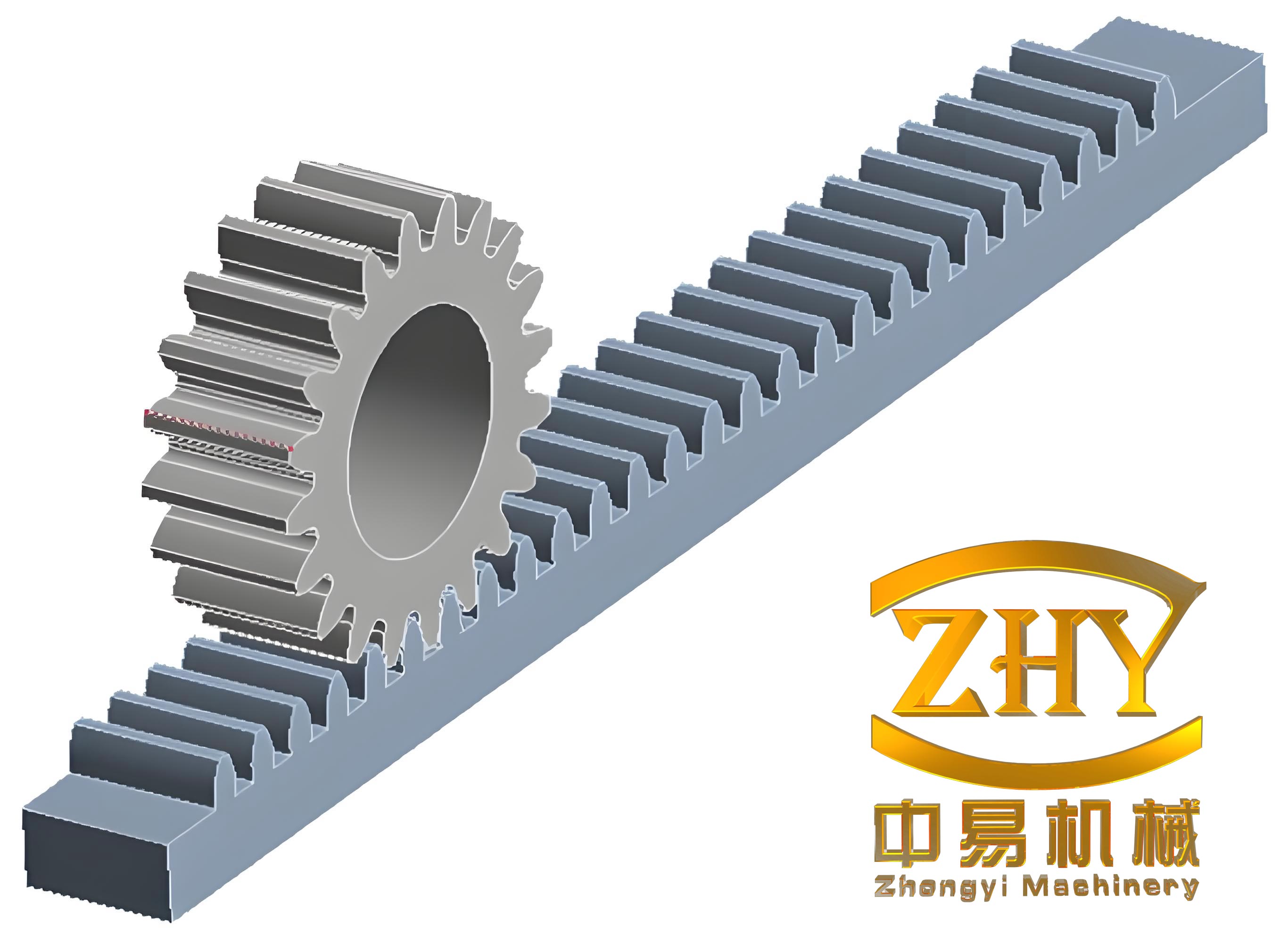
To ensure the rack and pinion gear system meets safety standards, I begin by determining the design parameters based on operational loads. The steering system must withstand forces from tire-road interaction, including friction, inertia, and impacts. I typically use semi-empirical formulas to calculate the steering resistance moment, which informs the required strength of the rack and pinion gear components. For instance, the moment $$M_R$$ on a paved surface can be approximated as:
$$M_R = \frac{f G_1 \sqrt[3]{p}}{10000} \quad \text{(N·mm)}$$
where $$f$$ is the sliding friction coefficient (usually 0.7), $$G_1$$ is the load on the steering axle in Newtons, and $$p$$ is the tire pressure in MPa. From this, the force on the steering wheel $$F_h$$ is derived:
$$F_h = \frac{2 M_R}{D_{sw} i \eta_+}$$
with $$D_{sw}$$ as the steering wheel diameter, $$i$$ as the steering ratio, and $$\eta_+$$ as the steering efficiency. For a rack and pinion gear system, the theoretical thrust on the rack $$F$$ is then computed, guiding the sizing of hydraulic components if power assistance is included. I often summarize these initial parameters in a table for clarity:
| Parameter | Symbol | Typical Value | Unit |
|---|---|---|---|
| Steering Axle Load | $$G_1$$ | 8000-12000 | N |
| Friction Coefficient | $$f$$ | 0.7 | – |
| Tire Pressure | $$p$$ | 0.2-0.3 | MPa |
| Steering Ratio | $$i$$ | 12-18 | – |
| Steering Efficiency | $$\eta_+$$ | 0.7-0.8 | – |
In power-assisted rack and pinion gear systems, the hydraulic power cylinder is integral. I design the cylinder to provide adequate force while minimizing size. The cylinder diameter $$D_c$$ is calculated based on the required thrust $$F$$ and supply pressure $$P$$ (typically 13 MPa):
$$D_c = \sqrt{\frac{4F}{\pi P \times 10^6} + d^2}$$
where $$d$$ is the piston rod diameter, often selected from standard series (e.g., 25 mm). For the rack and pinion gear assembly, the piston rod may be integrated with the rack for compactness. The piston stroke $$S$$ is determined by the rack travel and clearance, usually around 130 mm. Material selection is crucial: I use QT400-18 for the housing and ZL105 aluminum for the cylinder body, with surface hardness HB241-285 to resist wear. The wall thickness $$t$$ of the cylinder is checked for strength under internal pressure:
$$t = \frac{P D_c}{2 (\sigma_s / n)}$$
with $$\sigma_s$$ as the yield strength (160-230 MPa for ZL105) and $$n$$ as a safety factor of 3.5-5.0. This ensures the rack and pinion gear system can handle peak loads without failure.
Next, I focus on the rack and pinion gear itself, which is the heart of the steering mechanism. The gear design involves selecting module, number of teeth, and helix angle to achieve smooth operation and high strength. For passenger cars, I typically choose a module $$m_n$$ of 2 mm, a pinion with 8 teeth, and a helix angle $$\beta$$ of 12° to reduce noise and increase load capacity. The rack is designed with a corresponding tooth profile to mesh precisely. The key dimensions for the rack and pinion gear are calculated as follows:
$$d = \frac{m_n z}{\cos \beta}, \quad d_a = d + 2h_a^* m_n, \quad d_f = d – 2(h_a^* + c^*) m_n$$
where $$d$$ is the pitch diameter, $$d_a$$ is the addendum diameter, $$d_f$$ is the dedendum diameter, and $$h_a^*$$ and $$c^*$$ are coefficients (usually 1 and 0.25, respectively). For example, with $$z=8$$ and $$\beta=12^\circ$$, $$d \approx 16.4 \text{ mm}$$. The rack tooth height is similarly derived, ensuring full engagement. I often tabulate these geometric parameters:
| Parameter | Value | Unit |
|---|---|---|
| Module ($$m_n$$) | 2 | mm |
| Pinion Teeth ($$z$$) | 8 | – |
| Helix Angle ($$\beta$$) | 12 | degrees |
| Pitch Diameter ($$d$$) | 16.4 | mm |
| Addendum Diameter ($$d_a$$) | 20.4 | mm |
| Dedendum Diameter ($$d_f$$) | 11.4 | mm |
| Tooth Height ($$h$$) | 4.5 | mm |
Force analysis on the rack and pinion gear is critical for strength evaluation. The tangential force $$F_t$$ on the pinion is computed from the steering resistance moment $$M_R$$ and pitch radius. In a rack and pinion gear system, this force drives the rack laterally. The normal force $$F_n$$ is resolved into components:
$$F_t = \frac{2T}{d}, \quad F_n = \frac{F_t}{\cos \beta}, \quad F_r = F_n \tan \alpha_n / \cos \beta, \quad F_a = F_t \tan \beta$$
where $$T$$ is the torque input, $$\alpha_n$$ is the normal pressure angle (20°), and $$F_r$$ and $$F_a$$ are radial and axial forces, respectively. For a typical rack and pinion gear with $$T = 100 \text{ N·m}$$, $$F_t \approx 970.8 \text{ N}$$. These forces stress the teeth, necessitating fatigue checks. I use bending stress and contact stress formulas to verify the rack and pinion gear durability. The bending stress $$\sigma_F$$ is given by:
$$\sigma_F = \frac{K F_t Y_{Fa} Y_{Sa} Y_\epsilon}{b m_n \epsilon_\alpha}$$
where $$K$$ is the load factor (1.54 for dynamic conditions), $$Y_{Fa}$$ and $$Y_{Sa}$$ are form and stress correction factors (2.72 and 1.57 from handbook values), $$Y_\epsilon$$ is the spiral angle factor (0.7), $$b$$ is the face width (40 mm), and $$\epsilon_\alpha$$ is the transverse contact ratio (1.211). Substituting values, $$\sigma_F \approx 18.45 \text{ MPa}$$, well below the allowable $$[\sigma_F] = 303 \text{ MPa}$$ for 16MnCr5 steel. This confirms the rack and pinion gear teeth resist bending failure.
Contact stress $$\sigma_H$$ for the rack and pinion gear is equally important to prevent pitting. I apply the Hertzian formula:
$$\sigma_H = \sqrt{\frac{K F_t}{b d \epsilon_\alpha} \cdot \frac{u+1}{u} } \cdot Z_H Z_E$$
with $$u$$ as the gear ratio (1 for rack and pinion, as the rack has infinite radius), $$Z_H$$ as the zone factor (2.4), and $$Z_E$$ as the elasticity factor (188 for steel). For our rack and pinion gear, $$\sigma_H \approx 52.5 \text{ MPa}$$, lower than the permissible $$[\sigma_H] = 650-700 \text{ MPa}$$. This validates the surface durability of the rack and pinion gear pair. Material selection plays a key role here; I often use case-hardened steels like 20MnCr5 for the pinion and 45 steel for the rack to enhance wear resistance in the rack and pinion gear assembly.
Beyond the rack and pinion gear, other components require attention. The pinion shaft must withstand combined loads from torsion and bending. I design it using 20MnCr5 with carburizing, ensuring a fatigue limit $$[\sigma_{-1}] = 525 \text{ MPa}$$. The shaft diameter is derived from torque and stress criteria:
$$d_s \geq \sqrt[3]{\frac{16T}{\pi \tau_{allow}}}, \quad \tau_{allow} = 0.2 [\sigma_{-1}]$$
For $$T = 100 \text{ N·m}$$, $$d_s \approx 14.4 \text{ mm}$$, so a standard 20 mm shaft is safe. The rack, acting as a piston rod in hydraulic systems, is checked for buckling and tensile strength. With a diameter of 25 mm and length 585 mm, the critical load is computed using Euler’s formula for long columns. The rack and pinion gear system’s hydraulic side involves selecting a pump and reservoir. I prefer vane pumps for their quiet operation and compact size. The pump displacement $$Q$$ is estimated from steering dynamics:
$$Q = \frac{0.06 V_c d_s^2 \phi}{n_p \eta_v}$$
where $$V_c$$ is the cylinder volume, $$d_s$$ is the torsion bar diameter, $$\phi$$ is the steering wheel frequency (1.5-1.75 s⁻¹), $$n_p$$ is pump speed, and $$\eta_v$$ is volumetric efficiency (0.8). For a rack and pinion gear system, a pump like Y&D25 with 25 ml/rev capacity at 10 MPa suffices. The oil tank volume is sized for heat dissipation, typically 2-3 times the pump flow rate, and includes filters to maintain fluid cleanliness for the rack and pinion gear hydraulic circuit.
In my design process, I also consider manufacturing tolerances and assembly for the rack and pinion gear. The gear teeth are ground to achieve precise profiles, with backlash controlled via adjustable preload springs. I specify surface finishes—for example, the rack teeth have a roughness Ra ≤ 0.8 μm to reduce friction. Alignment between the rack and pinion gear is critical; I use jigs to ensure parallel within 0.02 mm over the length. Tables help summarize these specifications:
| Component | Material | Hardness | Tolerance |
|---|---|---|---|
| Pinion Gear | 20MnCr5 | 60 HRC | IT6 |
| Rack | 45 Steel | 55 HRC | IT7 |
| Housing | Aluminum Alloy | HB80 | ±0.1 mm |
| Piston Rod | 45 Steel | HRC30 | H8/f7 |
Environmental factors affect the rack and pinion gear performance. Temperature variations can alter fluid viscosity in power-assisted systems, so I include compensators in the design. Corrosion resistance is enhanced by plating the rack with chromium (0.03-0.05 mm thick). The rack and pinion gear system must also endure vibration; finite element analysis (FEA) models simulate stress distributions under shock loads. I often run simulations to optimize the rack and pinion gear geometry, reducing weight while maintaining strength. For instance, ribbing the housing can increase stiffness by 20% without adding bulk.
Safety is paramount in rack and pinion gear design. I incorporate fail-safes such as redundant seals to prevent hydraulic fluid leakage. The spring preload in the rack and pinion gear assembly is set to maintain contact even under wear, but it’s calibrated to avoid excessive steering effort. Crashworthiness is considered—the rack and pinion gear housing should deform controllably in impacts to protect occupants. I adhere to standards like ISO 26262 for functional safety, ensuring the rack and pinion gear system meets Automotive Safety Integrity Level (ASIL) B requirements.
Testing validates the rack and pinion gear design. Prototypes undergo endurance cycles on test rigs, simulating millions of steering maneuvers. I measure parameters like torque sensitivity and hysteresis to refine the rack and pinion gear response. Noise, vibration, and harshness (NVH) tests check for anomalies; for example, a well-designed rack and pinion gear should produce less than 70 dB during operation. Field data from similar rack and pinion gear systems in passenger cars inform improvements, such as using polymer coatings on the rack to dampen vibrations.
In conclusion, the rack and pinion steering system is a sophisticated assembly that demands careful engineering. From initial parameter selection to detailed strength calculations, every aspect of the rack and pinion gear must be optimized for performance and safety. I have found that integrating hydraulic assistance enhances usability without compromising the direct feel of the rack and pinion gear. By using advanced materials and precise manufacturing, the rack and pinion gear system can achieve long service life and reliability. This article summarizes my approach, emphasizing the rack and pinion gear’s role in modern passenger cars. As automotive technology evolves, innovations like electric power steering may augment the rack and pinion gear, but its fundamental principles remain vital. I hope this detailed exposition aids designers in creating robust steering solutions, always keeping the rack and pinion gear at the forefront of development.