
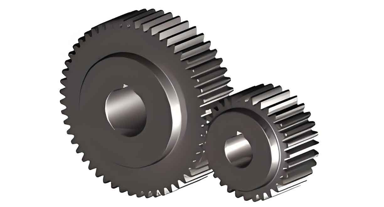
Spur gear drives are fundamental components in numerous mechanical systems, ranging from automotive transmissions to wind turbine gearboxes. In my research, I focus deeply on the time-varying meshing stiffness and dynamic behavior of spur gear pairs under compound faults, particularly when cracks and spalling occur simultaneously. The accurate calculation of the time-varying meshing stiffness of a spur gear is essential for predicting vibration response, diagnosing faults, and ensuring reliable operation. In this thesis, I propose an improved analytical model based on the energy method to compute the time-varying meshing stiffness of healthy, cracked, spalled, and combined crack-spalling spur gears. I further embed these stiffness results into a six-degree-of-freedom lumped parameter dynamic model to investigate the vibration signatures induced by different fault scenarios. I validate both the stiffness model and the dynamic model through finite element simulations and experiments.
1. Introduction
The spur gear is one of the most widely used transmission elements in industrial applications. In practice, spur gears are subjected to complex loads, variable speeds, and harsh environmental conditions. These factors may lead to various types of damage, such as tooth root cracks, tooth surface spalling, pitting, and even tooth breakage. Among these, cracks and spalling are the most common local faults. When a crack initiates at the tooth root or on the tooth surface, the effective cross-sectional area and the moment of inertia of the tooth decrease, resulting in a reduction of the time-varying meshing stiffness. Similarly, spalling removes material from the tooth surface, altering the contact geometry and causing additional torsional deformation. The combination of cracks and spalling, which I refer to as a composite fault, can make the stiffness variation more complicated and more destructive to the spur gear system.
In recent years, many researchers have developed analytical, numerical, and experimental methods to calculate the time-varying meshing stiffness of healthy and faulty spur gears. The energy method, based on cantilever beam theory, has become a popular approach because it provides explicit formulas for the bending, shear, axial compressive, Hertzian contact, and gear body stiffness components. However, most existing studies focus on a single fault type, such as only a crack or only spalling. In my work, I extend the energy method to consider multiple cracks, multiple spalls, and the coupling effect of crack and spalling on the same spur gear tooth or on different teeth. I also consider the structural coupling effect between simultaneously engaged teeth, which is often neglected in classical analytical models.
| Parameter | Symbol | Value |
|---|---|---|
| Number of teeth | z | 40 |
| Module | m | 3 mm |
| Face width | L | 20 mm |
| Pressure angle | α₀ | 20° |
| Young’s modulus | E | 206 GPa |
| Poisson’s ratio | ν | 0.3 |
| Hub bore radius | r_int | 20 mm |
| Mass | m | 1.226 kg |
| Moment of inertia | I | 2.577×10⁻³ kg·m² |
2. Time-Varying Meshing Stiffness of Healthy Spur Gears
To establish a baseline for fault analysis, I first calculated the time-varying meshing stiffness of a healthy spur gear pair. The gear tooth is modeled as a non-uniform cantilever beam fixed on the root circle. For a pair of meshing teeth, the total mesh stiffness \(k\) can be expressed as:
\[
k = \sum_{i=1}^{N} \frac{1}{\frac{1}{k_{h,i}} + \frac{1}{k_{t,i}^{p}} + \frac{1}{k_{f,i}^{p}} + \frac{1}{k_{t,i}^{g}} + \frac{1}{k_{f,i}^{g}}}
\]
where \(N=1\) for single-tooth contact and \(N=2\) for double-tooth contact. The superscripts \(p\) and \(g\) refer to the pinion and gear, respectively. The tooth stiffness \(k_t\) is composed of the bending stiffness \(k_b\), shear stiffness \(k_s\), and axial compressive stiffness \(k_a\):
\[
\frac{1}{k_t} = \frac{1}{k_b} + \frac{1}{k_s} + \frac{1}{k_a}
\]
The individual stiffness components can be derived using the energy method. In my model, I use angular displacement integration to obtain more accurate results for involute spur gears. For example, the bending stiffness \(k_b\) is given by:
\[
\frac{1}{k_b} = \int_{-\alpha_0}^{\beta} \frac{[\cos\beta (d-x) – \sin\beta h]^2}{EI_x} \, dx
\]
where \(d\) is the distance from the loading point to the fixed end, \(x\) is the distance along the tooth height, \(h\) is the arm of the bending moment, and \(I_x\) is the area moment of inertia at section \(x\). Similarly, the shear stiffness \(k_s\) is:
\[
\frac{1}{k_s} = \int_{-\alpha_0}^{\beta} \frac{1.2 \cos^2\beta}{GA_x} \, dx
\]
and the axial compressive stiffness \(k_a\) is:
\[
\frac{1}{k_a} = \int_{-\alpha_0}^{\beta} \frac{\sin^2\beta}{EA_x} \, dx
\]
The Hertzian contact stiffness \(k_h\) is calculated using the classical formula for two contacting cylinders:
\[
k_h = \frac{\pi E L}{4(1-\nu^2)}
\]
In addition, the gear body stiffness \(k_f\) is evaluated based on the Muskhelishvili elastic ring theory. Unlike conventional approaches that assume a constant stress distribution, I consider cubic normal stress and parabolic shear stress distributions at the root circle, which agree better with finite element results. Moreover, for multi-tooth contact, structural coupling effects are introduced. The total mesh stiffness of a healthy spur gear pair is then obtained by combining all components in series for each meshing pair.
To validate the analytical model, I built a finite element model of the same spur gear pair. In the finite element model, one gear is fully constrained and the other is loaded with a torque. The angular displacement of the loaded gear is extracted to calculate the time-varying meshing stiffness using the relationship:
\[
k = \frac{T}{r_b^2 \Delta \theta}
\]
where \(T\) is the applied torque, \(r_b\) is the base circle radius, and \(\Delta \theta\) is the angular displacement of the loaded spur gear. I found that the analytical results matched the finite element results well for all mesh positions, confirming the reliability of my energy-based model for healthy spur gears.
| Method | Maximum stiffness (N/m) | Minimum stiffness (N/m) |
|---|---|---|
| Analytical energy method | 3.42×10⁸ | 2.18×10⁸ |
| Finite element method | 3.38×10⁸ | 2.15×10⁸ |
| Relative error (%) | 1.2 | 1.4 |
3. Time-Varying Meshing Stiffness of Cracked Spur Gears
Cracks in spur gears usually initiate at the tooth root, where stress concentration is highest. In my analytical model, a crack is characterized by its depth \(q\), length \(l_s\) along the tooth width, angle \(\alpha_c\), and distance \(d_{cs}\) from the tooth centerline. To capture the non-uniform distribution of the crack along the tooth width, I divided the gear tooth into a number of thin slices, as shown in Figure 1 (in the original paper). Each slice is treated as an independent gear tooth with its own crack parameters. The total stiffness of a cracked spur gear is the sum of the slice stiffness values:
\[
k = \sum_{s=1}^{n} k_{slice,s}
\]
For each slice, the crack may extend into the gear body or remain entirely in the tooth. If the crack extends into the gear body, the gear body stiffness is modified by updating the geometric parameters \(S_f\), \(\beta\), and \(u_f\) in the elastic ring model. If the crack is confined to the tooth, only the bending and shear stiffness are affected because the effective cross-sectional area \(A_x\) and moment of inertia \(I_x\) are reduced. The effective values of \(A_x\) and \(I_x\) are calculated as:
\[
A_x = \begin{cases}
2 y_R L, & y \ge y_R \\
2 y L, & y < y_R
\end{cases}
\]
\[
I_x = \begin{cases}
\frac{1}{12} (2 y_R)^3 L, & y \ge y_R \\
\frac{1}{12} (2 y)^3 L, & y < y_R
\end{cases}
\]
In these expressions, \(y_R\) is the coordinate of the crack boundary, and \(y\) is the healthy tooth profile coordinate at the same distance from the root. I applied this model to several cracked spur gear cases with different crack depths and positions. For example, I considered two adjacent cracked teeth on the pinion. The time-varying meshing stiffness was calculated for crack depths \(q_1 = q_2 = 1\) mm, and the results were compared with the finite element method. The comparison showed excellent agreement, with the largest stiffness difference in the double-tooth contact zone where both cracked teeth meshed simultaneously.
I also investigated the influence of crack position \(d_{cs}\) on the adjacent cracked teeth. When two crack failure zones are both engaged at the same time, the stiffness reduction is much larger. If one crack is located far from the tooth root, its influence on the meshing stiffness decreases. In addition, I studied non-adjacent cracked teeth on the same spur gear. I found that if two cracked teeth do not mesh at the same time, their effects on the time-varying meshing stiffness are independent and additive. This means that non-adjacent cracks do not create additional coupling effects, which simplifies the fault diagnosis of a spur gear system with multiple cracks.
Another important case is multiple cracks on the same tooth. For example, a spur gear may have both a root crack and a surface crack on the same tooth. The failure regions of these cracks may not overlap, partially overlap, or completely overlap. I analyzed all three scenarios. When the failure regions do not overlap, the effective stiffness reduction is equal to the superposition of two independent cracks. When they partially overlap, the overlapping area must be considered only once. When they completely overlap, the stiffness is governed by the crack with the larger depth. My calculations show that the order and location of cracks on the same tooth have a significant effect on the time-varying meshing stiffness, and this cannot be captured by a single-crack model.
Finally, I analyzed the case where cracks are present on both the pinion and the gear. Since the two spur gears had the same number of teeth in my validation example, the mesh stiffness variation period was equal to one rotation cycle. Eight distinct stiffness components were identified: healthy pinion-healthy gear, cracked pinion-healthy gear, healthy pinion-cracked gear, cracked pinion-cracked gear, etc. The contributions of each component depend on the relative angular positions of the cracked teeth. These components are summarized in Table 3. The results provide a systematic understanding of how crack location and distribution affect the time-varying meshing stiffness of a spur gear pair.
| Component no. | Description | Duration (mesh cycles) |
|---|---|---|
| 1 | Healthy gear – Healthy pinion | 1 |
| 2 | Cracked gear – Cracked pinion | 1 |
| 3 | Healthy gear – Cracked pinion | 1 |
| 4 | Cracked gear – Healthy pinion | 1 |
| 5 | Cracked gear – Healthy pinion – Healthy gear | 1.5 |
| 6 | Healthy gear – Cracked pinion – Cracked gear | 1.5 |
| 7 | Cracked gear – Healthy pinion – Healthy gear – Cracked pinion | 2 |
| 8 | Healthy gear – Cracked pinion – Cracked gear – Healthy pinion | 2 |
4. Time-Varying Meshing Stiffness of Spalled Spur Gears
Spalling is a surface fatigue defect commonly observed on the tooth flanks of spur gears. Unlike cracks that affect the tooth cross-section, spalling removes a finite volume of material from the tooth surface, which changes the Hertzian contact stiffness and introduces an additional torsional deformation when the spalling is not centered on the face width. In my work, I developed a shape-independent model for spalled spur gears, meaning that the spalling shape can be arbitrary as long as the length, depth, and offset are defined.
For a spalled spur gear tooth, the tooth stiffness \(k_t\) must include a torsional component \(k_\tau\) because the off-center removal of material creates an unbalanced moment. Therefore:
\[
\frac{1}{k_t} = \frac{1}{k_a} + \frac{1}{k_b} + \frac{1}{k_s} + \frac{1}{k_\tau}
\]
The torsional stiffness \(k_\tau\) is expressed through the polar moment of inertia \(I_p\) and the distance between the spall center and the gear midplane \(p\). I defined defect ratios for the spall length, depth, and offset at each position \(x\) along the tooth height:
\[
C_{L_s x} = \frac{L_s(x)}{L}, \quad C_{h_s x} = \frac{h_s(x)}{h(x)}, \quad C_{p_s x} = \frac{p_s(x)}{L}
\]
Using these ratios, the effective cross-sectional area and moment of inertia of the spalled tooth section can be computed for any section. The shear stiffness and bending stiffness are then obtained by integrating along the tooth profile, accounting for the definite boundaries of the spall. The total mesh stiffness of a spalled spur gear pair is:
\[
k = \sum_{i=1}^{N} \frac{1}{\frac{1}{k_{h,i}} + \frac{1}{k_{a,i}} + \frac{1}{k_{b,i}} + \frac{1}{k_{s,i}} + \frac{1}{k_{\tau,i}} + \frac{1}{k_{f,i}}}
\]
I verified this model using a finite element simulation of a spur gear pair with two adjacent spalled teeth. The spall parameters were \(L_s = 6\) mm, \(p = 4\) mm, and \(h_s = 0.9\) mm for the first tooth, and \(L_s = 4\) mm, \(p = 2\) mm for the second tooth. The analytical time-varying meshing stiffness curve closely followed the finite element result in the mesh cycles where the spalls were active. This confirms that my shape-independent spalling model is accurate for multiple spalls on a spur gear.
I also studied non-adjacent spalled teeth on the same gear. When two spalls are located far apart so that they never enter the contact zone simultaneously, their effects on the stiffness are independent. Each spall causes a local reduction in the time-varying meshing stiffness when its corresponding tooth meshes, and the stiffness returns to the healthy value once the spalled tooth leaves contact. This behavior is analogous to the non-adjacent crack case, indicating that local faults do not interact strongly if they are not in contact at the same time.
For the case of multiple spalls on the same tooth, I considered two spalls located on the same side of the tooth centerline and on opposite sides. When the spalls are on the same side, the torsional effects add up, leading to a lower stiffness compared to the case where the spalls are on opposite sides. The interaction of the two spall zones during the mesh cycle also changes the shape of the stiffness curve. Through this analysis, I found that the distribution of spalls on a single spur gear tooth must be carefully considered in the stiffness calculation because the resulting torsional deformation can significantly affect the mesh stiffness value.
| Spall number | Length \(L_s\) (mm) | Depth \(h_s\) (mm) | Offset \(p\) (mm) | Center position (mm) | Angle \(\theta_s\) (°) |
|---|---|---|---|---|---|
| 1 | 3 | 2 | 2.5 | 40 | 30 |
| 2 | 3 | 2 | 4 | 40 | 30 |
| 3 | 3 | 2 | 3.2 | 40 | 30 |
| 4 | 2 | 1 | 5.5 | 41 | 40 |
5. Combined Crack-Spalling Spur Gear Stiffness
In many real-world situations, a spur gear may suffer from both cracking and spalling simultaneously. This composite fault is more challenging to diagnose because the effects of the two fault types are superimposed and may interact with each other. In my research, I combined the crack model and the spalling model to calculate the time-varying meshing stiffness of a spur gear pair with a composite fault.
When the crack and spalling are located on different teeth, the total stiffness can be obtained by directly combining the stiffness formulas from the previous two sections, because the load on each tooth pair is independent. For example, if one tooth has a crack and the adjacent tooth has spalling, the first two mesh cycles will see a combination of the two fault effects. I compared my analytical results with finite element simulations for the adjacent crack-spalling case. The agreement was very good, particularly in the second mesh cycle where both faulty teeth were engaged simultaneously.
When the crack and spalling are located on the same tooth, the effective cross-sectional area and moment of inertia are affected by both defects. In my model, I treat the crack as a reduction in the tooth cross-section, and the spalling as an additional removal of material from the surface. The overlapping zone between the two failure areas must be subtracted to avoid double-counting. The meshing stiffness of such a composite spur gear tooth is calculated using the modified section properties. I observed that the influence of the composite fault depends strongly on the relative positions of the crack and the spalling. For instance, when the crack is located before the spalling along the tooth height, the stiffness reduction is larger than when the crack is located after the spalling.
I also studied the case where cracks and spalls are present on both the pinion and the gear. Just like the multi-crack and multi-spall cases, eight distinct stiffness components can be identified depending on which teeth are faulty. The time-varying meshing stiffness curves for these eight components are shown in the paper. They help to explain the complex modulation patterns observed in the vibration spectrum of a spur gear with composite faults.
| Scenario | Average stiffness reduction (%) | Maximum stiffness reduction (%) |
|---|---|---|
| Single root crack on pinion tooth | 4.8 | 7.2 |
| Single spall on pinion tooth | 3.5 | 5.1 |
| Crack and spalling on adjacent teeth | 6.9 | 11.3 |
| Crack and spalling on the same tooth | 8.2 | 14.6 |
| Crack on pinion + spalling on gear | 7.5 | 12.4 |
6. Dynamic Modeling of Faulty Spur Gear Systems
After obtaining the time-varying meshing stiffness of the faulted spur gear, I established a six-degree-of-freedom lumped parameter dynamic model to study the vibration response of the gear system. The model includes two translational degrees of freedom for each gear and one rotational degree of freedom for each gear, accounting for the flexibility of the supporting bearings. The equations of motion can be written as:
\[
\begin{aligned}
m_p \ddot{x}_p + c_{px} \dot{x}_p + k_{px} x_p &= -k \delta \cos\alpha_0 \\
m_p \ddot{y}_p + c_{py} \dot{y}_p + k_{py} y_p &= -k \delta \sin\alpha_0 \\
I_p \ddot{\theta}_p + c_p \dot{\theta}_p + r_{bp} k \delta &= T_p \\
m_g \ddot{x}_g + c_{gx} \dot{x}_g + k_{gx} x_g &= k \delta \cos\alpha_0 \\
m_g \ddot{y}_g + c_{gy} \dot{y}_g + k_{gy} y_g &= k \delta \sin\alpha_0 \\
I_g \ddot{\theta}_g + c_g \dot{\theta}_g + r_{bg} k \delta &= -T_g
\end{aligned}
\]
where \(m_p, m_g\) are the masses, \(I_p, I_g\) are the moments of inertia, \(k_{px}, k_{py}, k_{gx}, k_{gy}\) are the bearing stiffness values, \(c_{px}, c_{py}, c_{gx}, c_{gy}\) are the bearing damping coefficients, and \(T_p, T_g\) are the input and load torques. The relative displacement \(\delta\) along the line of action is expressed as:
\[
\delta = (x_p – x_g) \cos\alpha_0 + (y_p – y_g) \sin\alpha_0 + r_{bp} \theta_p – r_{bg} \theta_g – e(t)
\]
where \(e(t)\) is the static transmission error, which in my model is written as a harmonic function of the mesh frequency: \(e(t) = e_0 + e_r \sin(\omega_m t + \varphi_m)\). The mesh damping \(c\) is calculated from the mesh stiffness \(k\) using the following relation:
\[
c = 2 \xi_m \sqrt{k \frac{m_p m_g}{m_p + m_g}}
\]
with the damping ratio \(\xi_m = 0.1\). The time-varying meshing stiffness \(k\) from the analytical fault models is directly introduced into the dynamic model as an internal excitation. I solved the nonlinear differential equations using the Runge-Kutta method and computed the steady-state acceleration response of the gearbox housing.
For the spur gear pair used in the dynamic simulation, I selected the parameters listed in Table 6. The input speed was set to 1000 rpm, corresponding to a shaft frequency \(f_s = 16.67\) Hz and a mesh frequency \(f_m = 433.3\) Hz. The load torque was approximately 30 N·m. In the time-domain response, I observed distinct periodic impulses for each fault case. The time interval between consecutive impulses was equal to the shaft rotation period \(T_s = 0.06\) s, because each faulty tooth meshes once per revolution. In the frequency domain, the FFT spectra showed the mesh frequency and its harmonics, surrounded by sidebands spaced at the shaft frequency. The presence of sidebands is a typical indicator of a localized fault in a spur gear.
| Parameter | Value |
|---|---|
| Number of teeth (pinion) | 26 |
| Number of teeth (gear) | 31 |
| Module (mm) | 3 |
| Face width (mm) | 25 |
| Pressure angle (°) | 20 |
| Mass (pinion/gear) (kg) | 0.988 / 1.02 |
| Moment of inertia (pinion/gear) (kg·m²) | 1.81×10⁻³ / 1.87×10⁻³ |
| Bearing stiffness (N/m) | 3×10⁸ |
| Bearing damping (N·s/m) | 1.5×10⁵ |
7. Experimental Validation and Discussion
To verify the simulation results, I built a spur gear fault test rig. The test rig consisted of a three-phase asynchronous motor, a controller, a test gearbox, and a magnetic powder brake. An accelerometer was mounted on the gearbox housing to measure the radial vibration acceleration. The sampling frequency was 20 kHz, and the input shaft speed was kept at 1000 rpm. I implanted different types of faults into the gear teeth using wire electrical discharge machining for cracks and mechanical machining for spalls. The parameters of the experimental faults are summarized in Table 4 (for spalls) and in the text (for cracks).
For the adjacent cracked teeth case, the measured acceleration waveform showed periodic impulses with a spacing of approximately 0.06 seconds, which matched the shaft rotation period. The FFT spectrum of the experimental signal exhibited a clear peak at the mesh frequency and multiple harmonics, with sidebands indicating the presence of the crack. The simulation and experiment results were in good agreement, although the experimental spectrum contained more background noise and slight frequency shifts due to speed fluctuations. I attributed these discrepancies to the unavoidable non-uniformity of the motor speed and manufacturing tolerances.
For the multi-spall case, the time-domain response contained several impulses within each shaft cycle. The number of impulses corresponded to the number of spalled teeth. In my experiment, three adjacent teeth with spalling produced three consecutive impulses, followed by a quiet period until the next revolution. The FFT spectrum showed a distinctive modulation pattern, with sidebands spaced at the shaft frequency. The strongest impulse was produced by the tooth with two overlapping spalls, demonstrating that the spalling area and depth significantly affect the vibration amplitude.
For the composite crack-spalling fault, both the time-domain and frequency-domain characteristics differed from those of a single fault. In the adjacent crack-spalling case, two impulses appeared very close to each other, corresponding to the two faulty teeth. In the same-tooth crack-spalling case, only one impulse per shaft cycle was observed, but its amplitude was larger and the sideband structure in the FFT spectrum was more complex. A comparison of the experimental and simulated FFT spectra for the same-tooth composite fault is shown in Table 7. The dominant frequencies and sideband spacing are consistent, confirming that my analytical model captures the essential dynamics of a spur gear with composite faults.
| Frequency component | Simulation (Hz) | Experiment (Hz) | Relative error (%) |
|---|---|---|---|
| Mesh frequency \(f_m\) | 433.3 | 435.0 | 0.4 |
| 2nd harmonic | 866.7 | 870.0 | 0.4 |
| 3rd harmonic | 1300.0 | 1305.0 | 0.4 |
| Sideband spacing | 16.67 | 16.7 | 0.2 |
8. Conclusion
In this thesis, I performed a systematic investigation of the time-varying meshing stiffness and dynamic response of spur gear systems with multiple cracks, multiple spalls, and combined crack-spalling composite faults. Through theoretical derivation, finite element validation, and experimental testing, I obtained the following conclusions:
First, my analytical method based on the energy method and slice modeling can accurately predict the time-varying meshing stiffness of a spur gear under various fault conditions. The finite element comparisons confirmed the accuracy of my model in the single and double tooth contact regions.
Second, I found that the presence of multiple faults significantly reduces the time-varying meshing stiffness of a spur gear. When faults are located on non-adjacent teeth, their effects are independent. When they are on the same tooth or on adjacent teeth, the interaction between the fault zones produces a combined stiffness reduction that is larger than that caused by any single fault. The order of engagement of the faulty teeth also influences the stiffness profile.
Third, the dynamic analysis of the faulty spur gear system showed that localized faults generate periodic impulses in the vibration acceleration, with a period equal to the shaft rotation period. In the frequency domain, these impulses create sidebands around the mesh frequency and its harmonics. Composite faults produce more complex sideband patterns and higher peak amplitudes than single faults. Multi-tooth faults create multiple impulses within one shaft revolution, whereas multiple faults on the same tooth typically produce one dominant impulse.
Finally, the experimental results closely matched the simulation results, validating the proposed analytical model and the dynamic simulation framework. This work provides a useful tool for fault diagnosis and health monitoring of spur gear systems, especially when multiple faults coexist.