
In my extensive study of automotive steering mechanisms, I have dedicated significant attention to the rack and pinion gear system, a cornerstone of vehicle control. The rack and pinion steering gear, with its simple yet effective design, has undergone a remarkable transformation since its inception. I aim to delve into this structural evolution, highlighting key innovations, performance enhancements, and the underlying engineering principles that have shaped its modern form. This analysis will be enriched with comparative tables and mathematical formulations to provide a comprehensive understanding of the rack and pinion gear’s development.
The journey of the rack and pinion gear began in the late 19th century. Historical records indicate that the first “modern” application of a rack and pinion steering system was in 1885 on a German Benz automobile. This pioneering use marked the beginning of a technology that would later find its way onto American vehicles like the 1905 Cadillac and numerous other cars. For over a century, the rack and pinion gear has persisted, its structure and performance refined through continuous engineering efforts. In the realm of manual steering systems, two primary categories exist: the rack and pinion steering system and the recirculating-ball type steering system, which utilizes a pitman arm as its final output element. My focus remains firmly on the former, tracing its path from a rudimentary mechanism to a sophisticated, widely adopted component.
At its core, a rack and pinion steering gear consists of a pinion (a small gear) and a rack (a linear gear), housed within a corresponding壳体. The rack and pinion gear pair forms a backlash-free啮合副 whose primary function is to convert the rotary motion of the pinion into the reciprocating linear motion of the rack. This transformation not only changes the direction of motion but also provides a mechanical advantage by增大 the传动比. The fundamental kinematics can be described by the relationship between pinion rotation and rack displacement. If the pinion has a number of teeth \( N_p \) and a module \( m \), and the rack has a corresponding齿条模数, the linear displacement of the rack \( x \) for a pinion rotation angle \( \theta \) (in radians) is given by:
$$ x = r_p \theta = \frac{m N_p}{2} \theta $$
where \( r_p \) is the pitch radius of the pinion. The传动比 of the steering system, relating steering wheel angle to wheel turning angle, is influenced by this gear ratio and the linkage geometry.
The efficiency of the rack and pinion gear transmission is notably high, and the system is reversible. This reversibility, while beneficial for feedback, poses a challenge: it allows road shocks from uneven surfaces to be transmitted back to the steering wheel. To mitigate this反向冲击, early designs incorporated various damping mechanisms. One historical solution involved a preload spring assembly. This assembly, comprising a spring placed between two inner washers in the housing and two outer washers seated in grooves on the rack shaft, absorbed shocks below the spring’s preload force. Thus, impacts from road irregularities were dissipated through the spring, housing, and vehicle frame before reaching the driver. The force balance required to move the rack axially must overcome both this spring preload and the wheel turning resistance. Rack travel and wheel angle limits were physically enforced by limit stops.
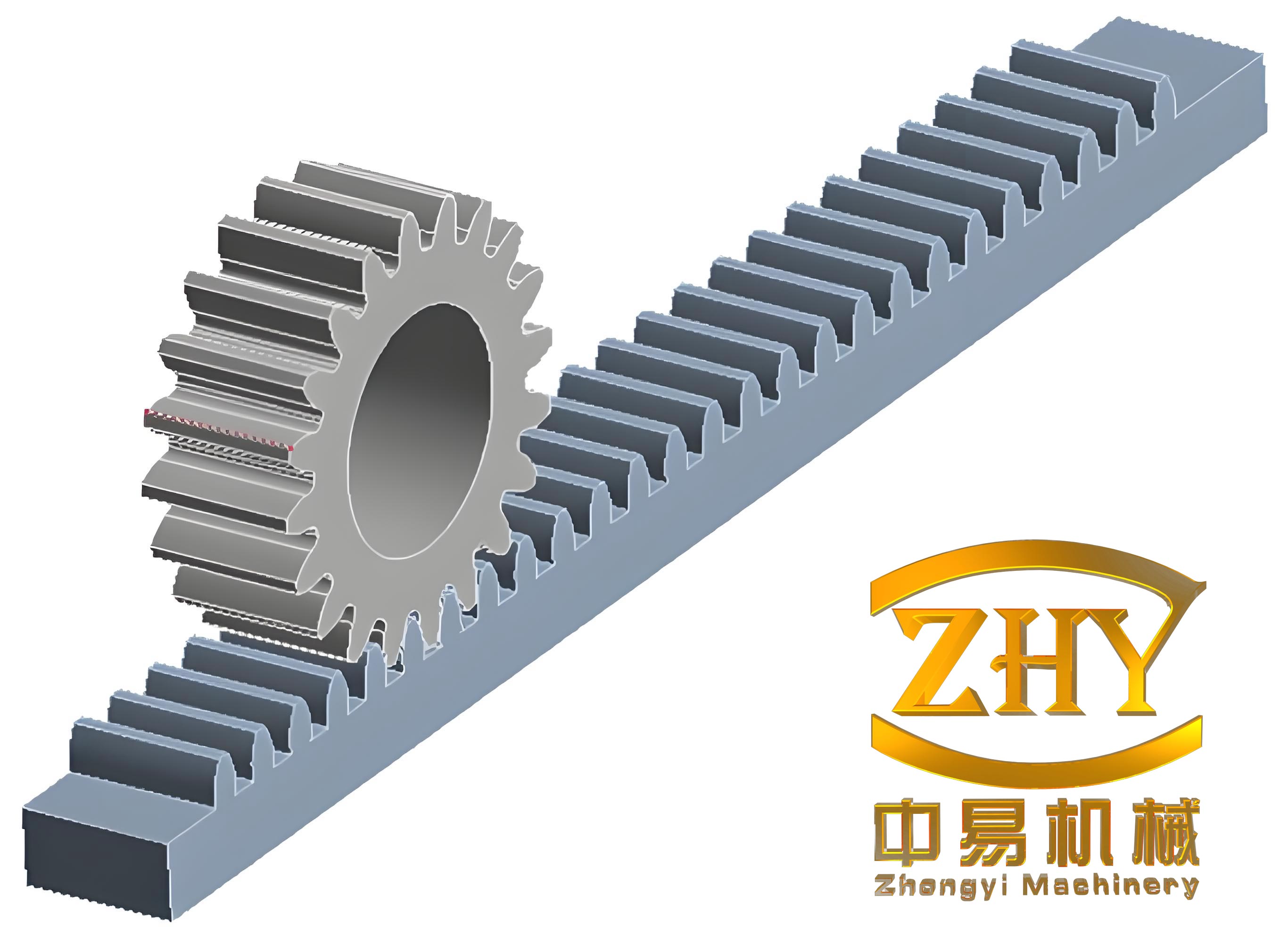
A pivotal evolution in the rack and pinion gear design was the transition from straight-cut teeth to helical teeth. Early rack and pinion gears utilized spur gears with straight teeth. The啮合 characteristics of such gears involve the entire tooth width engaging and disengaging simultaneously. This sudden loading and unloading on the pinion teeth led to significant noise, impact, and poor operational smoothness. Furthermore, the geometry constrained the pinion axis to be perpendicular to the rack, limiting adaptability in vehicle packaging. The adoption of helical pinion gears and helical rack teeth addressed these shortcomings. The advantages of helical teeth in a rack and pinion gear are substantial, as summarized in the following table:
| Characteristic | Straight Teeth (Spur Gears) | Helical Teeth |
|---|---|---|
| Tooth Contact | Line contact along the full face width. Engagement/disengagement is abrupt. | Point contact initially, evolving into line contact. Contact lines are inclined. Engagement is gradual. |
| Noise and Vibration | High due to sudden load changes. | Significantly reduced due to gradual tooth entry and exit. |
| Overlap Coefficient (ε) | Lower, typically around 1.0 to 1.5. | Higher, increases with face width and helix angle \( \beta \). Formula: \( \epsilon = \epsilon_\alpha + \epsilon_\beta \), where \( \epsilon_\beta = \frac{b \sin \beta}{\pi m_n} \). |
| Axial Thrust | None. | Present, generating a force \( F_a = F_t \tan \beta \), requiring thrust bearings. |
| Packaging Flexibility | Limited; pinion axis fixed perpendicular to rack. | High; varying pinion helix angles and rack tooth angles allow diverse installation angles. |
| Manufacturing Cost | Generally lower. | Comparable for modern production methods. |
The overlap coefficient \( \epsilon \) is a critical metric for gear smoothness. For a rack and pinion gear with helical teeth, the total overlap coefficient is the sum of the transverse overlap \( \epsilon_\alpha \) and the face overlap \( \epsilon_\beta \). A higher \( \epsilon \) indicates more teeth are in contact simultaneously, distributing load and reducing stress per tooth. The formula for the face overlap component is:
$$ \epsilon_\beta = \frac{b \sin \beta}{\pi m_n} $$
where \( b \) is the face width, \( \beta \) is the helix angle, and \( m_n \) is the normal module. This directly contributes to the quiet and smooth operation of modern helical rack and pinion gears.
However, the helical rack and pinion gear introduces an axial thrust force. This force \( F_a \) is related to the tangential force \( F_t \) on the pinion and the helix angle:
$$ F_a = F_t \tan \beta $$
This necessitates the use of thrust bearings, which, while adding a small amount of friction, is a worthwhile trade-off for the substantial improvements in noise and durability. The ability to tailor the helix angle also provides engineers with a powerful tool for optimizing the rack and pinion gear for specific vehicle layouts, achieving desired steering feel and ratio characteristics.
Another crucial aspect of rack and pinion gear evolution is the compensation for wear and manufacturing tolerances. To maintain optimal啮合 and eliminate backlash over the system’s lifespan, adjustment mechanisms are essential. In early straight-tooth rack and pinion gears,间隙 adjustment was often achieved via an eccentric bushing on the pinion shaft or a separate housing for the pinion that allowed positional adjustment. Later, designs experimented with bevel gear and rack pairs, using shims for adjustment. The contemporary solution for helical rack and pinion gears typically involves a spring-loaded plunger or a弹簧托座 bearing against the back of the rack. This component applies a constant force, pushing the rack teeth against the pinion teeth, thereby automatically taking up any wear-induced slack. This ensures consistent, rattle-free operation throughout the life of the rack and pinion steering gear.
The durability and wear characteristics of the rack and pinion gear pair are paramount. From mechanical principles, the sliding coefficient, which indicates the relative sliding velocity between mating teeth, is not uniform. Typically, the sliding coefficient at the tooth root is greater than at the tooth tip. Furthermore, for a pinion and rack, the pinion tooth root experiences a higher sliding coefficient than the rack tooth root. Since the pinion undergoes more stress cycles, it is more prone to wear and failure. To equalize wear and improve overall life, several strategies are employed in designing a rack and pinion gear. First, material selection: the pinion is often made from more wear-resistant材料, such as low-carbon alloy steel subjected to carburizing and quenching to achieve a hard, wear-resistant surface. Second, profile modification: the rack tooth tip can be shortened, and the pinion tooth tip can be enlarged to balance the sliding coefficients. The sliding velocity \( v_s \) at a point on the tooth profile can be derived from the geometry of engagement.
Third, and most importantly, the use of profile shift or变位修正 on the pinion gear. In a standard rack and pinion gear, the pinion, being the smaller member, has a thinner tooth root and a smaller radius of curvature at the contact point, leading to lower bending and contact strength compared to the rack. To mitigate this, a positive profile shift (positive addendum modification) is applied to the pinion. This modification increases the pinion’s tooth thickness \( s \) and addendum \( h_a \), while decreasing its dedendum \( h_f \). The basic tooth thickness formula for a gear with profile shift coefficient \( x \) is:
$$ s = m \left( \frac{\pi}{2} + 2x \tan \alpha \right) $$
where \( m \) is the module and \( \alpha \) is the pressure angle. A positive \( x \) for the pinion enhances its bending strength and reduces specific sliding at the root, promoting more balanced wear with the rack. This careful optimization of geometry and materials is essential for the long-term reliability of the rack and pinion gear.
To quantify the contact stress in a rack and pinion gear, which is critical for pitting resistance, the Hertzian contact stress formula can be applied. For two cylinders in contact (approximating the tooth contact), the maximum contact pressure \( p_{max} \) is:
$$ p_{max} = \sqrt{ \frac{F E^*}{\pi \rho^*} } $$
where \( F \) is the normal load per unit width, \( E^* \) is the equivalent Young’s modulus, and \( \rho^* \) is the equivalent radius of curvature. For a helical rack and pinion gear, the contact occurs on an elliptical area, and the calculation incorporates the helix angle and the normal plane geometry. Minimizing this stress through design optimization directly contributes to the durability of the rack and pinion steering system.
The performance parameters of a rack and pinion steering system can be further summarized in the following table, which contrasts key attributes across its evolutionary stages:
| Era / Phase | Tooth Geometry | Backlash Compensation | Key Advantages | Primary Limitations |
|---|---|---|---|---|
| Early (Late 19th – Mid 20th Century) | Straight (Spur) Teeth | Eccentric bushings, shims (manual adjustment) | Conceptual simplicity, direct mechanical action. | Noisy, prone to shock transmission, limited packaging flexibility. |
| Transitional | Bevel gear variants, early helical attempts | Shim-based adjustment for bevel sets. | Improved angle flexibility for bevel types. | Complex manufacturing, adjustment still manual. |
| Modern (Late 20th Century – Present) | Helical Teeth (Pinion and Rack) | Spring-loaded automatic adjuster (e.g., plunger against rack back). | Quiet operation, high overlap ratio, excellent packaging flexibility, automatic wear compensation. | Axial thrust requires management via thrust bearings. |
| Advanced / Future Trends | Optimized helical profiles, potential for non-circular gears for variable ratio. | Integrated electronic control in steer-by-wire systems (though the physical rack and pinion gear may be absent). | Ultra-high precision, tailored steering feel, integration with driver-assist systems. | Increased complexity, cost, and reliability demands. |
The structural simplicity of the rack and pinion gear is one of its greatest strengths. Compared to recirculating-ball systems, it typically has fewer parts, leading to lower weight, reduced cost, and inherently higher刚性. The direct connection between the pinion and the rack provides a precise and immediate steering response, often described as offering better “road feel.” For decades, the rack and pinion gear faced limitations due to perceived issues with noise and shock from poor road conditions. However, the innovations discussed—helical teeth, automatic wear compensation, and advanced materials—have effectively addressed these concerns. Today, the rack and pinion steering system stands as an equal to the once-dominant recirculating-ball system in many vehicle segments, and in front-wheel-drive and compact vehicle applications, it has become the overwhelmingly preferred choice. Its evolution is a testament to iterative engineering improvement.
In my analysis, the mathematical modeling of rack and pinion gear dynamics is essential for modern design. The system’s transfer function, relating steering wheel torque to rack force, involves the gear mesh stiffness, damping, and inertia. A simplified equation of motion for the rack, neglecting damping for clarity, can be expressed as:
$$ m_r \ddot{x} + k_m (x – r_p \theta_p) = F_{ext} $$
where \( m_r \) is the effective mass of the rack, \( k_m \) is the mesh stiffness of the rack and pinion gear pair, \( x \) is rack displacement, \( \theta_p \) is pinion angular displacement, and \( F_{ext} \) is the external force from the tie rods. The mesh stiffness \( k_m \) is not constant but varies with the number of teeth in contact, which is directly influenced by the overlap coefficient \( \epsilon \) of the helical rack and pinion gear.
Furthermore, the efficiency \( \eta \) of the rack and pinion gear transmission affects the steering feel. It can be estimated considering friction losses in the gears, seals, and bearings. An expression accounting for gear friction might take the form:
$$ \eta \approx 1 – \frac{\mu F_n v_s}{T_p \omega_p} $$
where \( \mu \) is a friction coefficient, \( F_n \) is the normal tooth force, \( v_s \) is the average sliding velocity, \( T_p \) is the input torque on the pinion, and \( \omega_p \) is its angular velocity. Optimizing this efficiency is a key goal in refining the rack and pinion steering system.
Looking forward, the role of the rack and pinion gear continues to evolve. In electric power steering (EPS) systems, a rack and pinion gear is often coupled with an electric motor assist mechanism, either directly on the rack (column-drive or pinion-drive) or via a dual-pinion setup. The fundamental rack and pinion gear remains the mechanical heart of these systems, providing the essential motion conversion. The design challenges shift towards integrating sensors for torque and position, optimizing for reduced friction to maximize electric assist efficiency, and ensuring compatibility with advanced driver-assistance systems (ADAS) that may require automatic steering interventions.
In conclusion, the structural evolution of the rack and pinion steering gear is a fascinating narrative of mechanical engineering refinement. From its straightforward beginnings with straight-cut teeth to the sophisticated, helical-tooth systems with automatic compensation, every change has been driven by the pursuit of better performance, durability, and adaptability. The rack and pinion gear, through sustained innovation, has overcome its early limitations to become a dominant and highly reliable steering technology. Its future lies in seamless integration with electronic control systems, all while retaining the inherent virtues of simplicity and direct mechanical feedback that have always defined the essence of the rack and pinion gear.