
In the field of gear manufacturing, the cutting of helical bevel gears presents a complex set of challenges due to the intricate geometry and kinematic relationships involved. As an engineer specializing in gear design and production, I have often encountered the need for approximate calculations to simplify the process while maintaining acceptable accuracy. This article delves into the inherent approximations in the cutting calculations for helical bevel gears, exploring the theoretical foundations, practical adjustments, and their implications on gear performance. The helical bevel gear is a critical component in many mechanical systems, such as automotive differentials and aerospace transmissions, where its ability to transmit power smoothly at high speeds is paramount. However, the manufacturing process relies on a series of simplifications that introduce approximations, which I will analyze in detail.
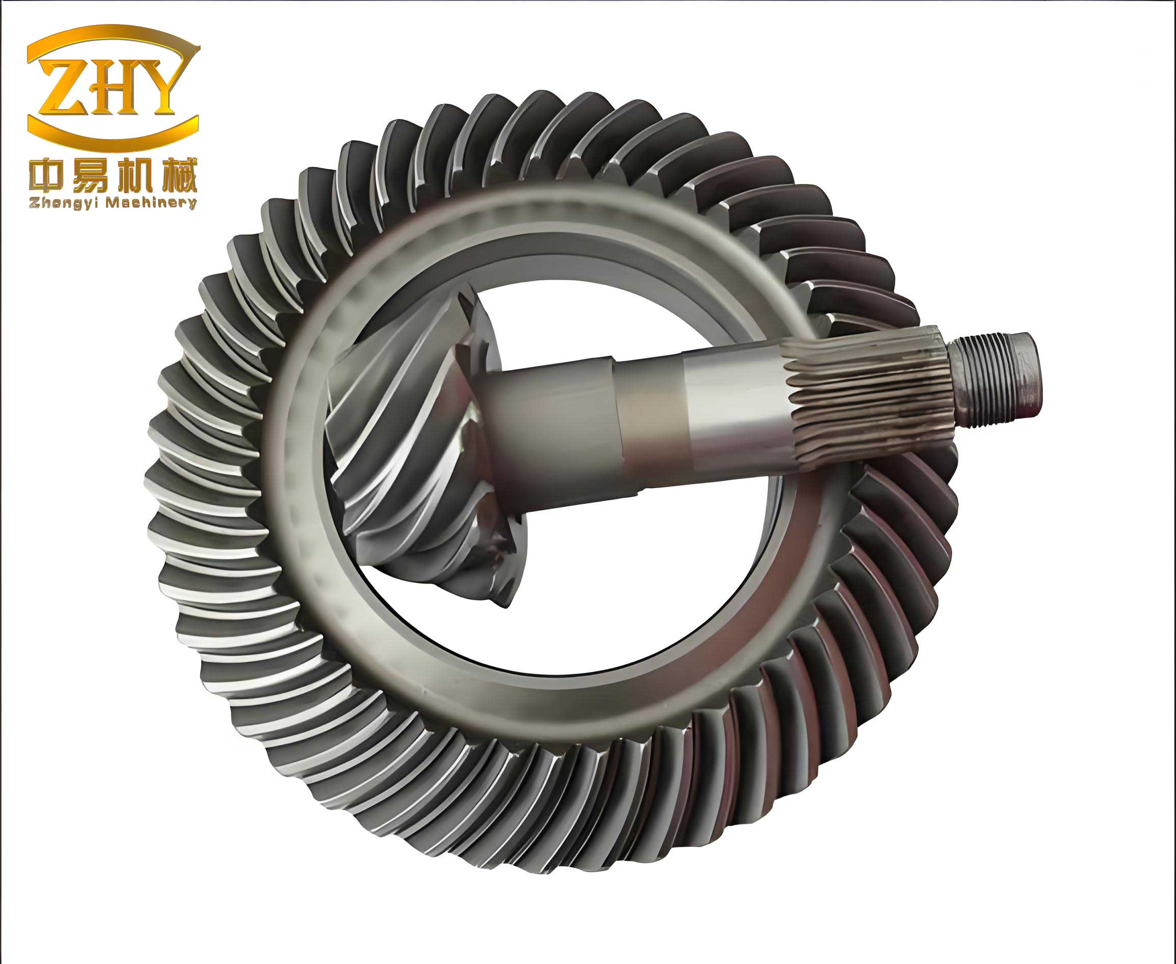
The cutting calculations for helical bevel gears are derived from a sequence of approximate computations, primarily based on the conditions at the midpoint of the tooth flank. This focus on the central region is justified by the practical requirement for localized contact, which arises from elastic deformation under load, leading to a contact zone rather than line contact. In this discussion, I will examine the key aspects of these approximations, including the conditions for approximation, the tool number issue and diagonal contact, and the correction of spiral angles. Throughout, I will emphasize the role of the helical bevel gear in these calculations, and I will use formulas and tables to summarize the relationships. The image below illustrates a typical helical bevel gear pair, highlighting their complex tooth geometry.
The fundamental condition for approximation in helical bevel gear cutting stems from the replacement of an ideal plane crown gear with a practical flat-top gear. In theory, the instantaneous contact line between a gear and a crown gear is the perpendicular projection of the instantaneous axis onto the tooth surface. For correct meshing, the normal at any contact point must pass through the instantaneous axis. When manufacturing a pair of helical bevel gears, both the pinion and the gear should have instantaneous contact lines that coincide with those of the crown gear at the same cone distance. However, in actual cutting machines, especially for non-equidistant teeth, the use of a flat-top gear instead of a plane crown gear means that the two crown gears used for cutting the pinion and gear cannot perfectly match. Consequently, the instantaneous contact lines for the pinion and gear do not align, resulting in point contact at any given moment rather than line contact. From a theoretical perspective, this implies that the gears cannot mesh correctly, necessitating a series of corrections in machine tool adjustments.
In practice, to achieve localized contact, the tooth flank curvatures of the mating gears are deliberately made slightly different. This ensures that only a point contact occurs at the midpoint of the tooth flank, but due to elastic deformation, an elliptical contact area forms under load. This localized contact allows us to focus our analysis on the vicinity of the tooth midpoint, which serves as the basis for all subsequent approximate calculations. The helical bevel gear’s geometry is defined by parameters such as pressure angle, spiral angle, and root angle, which I will refer to frequently in the derivations.
Let us first consider the tool number problem and its relation to diagonal contact. When a flat-top gear is used, the pressure angle at points away from the midpoint deviates from the nominal value. This deviation arises because the cutting tool must be rotated to account for the root angle of the gear being cut. Specifically, if we denote the pressure angle as $\phi$, the spiral angle at the midpoint as $\beta$, and the root angle as $\delta$, then the tool rotation can be decomposed into two components: one around the axis tangent to the tooth line and another around the axis perpendicular to it. The component around the tangent axis affects the pressure angle, leading to a deviation $\Delta \phi$. For a small rotation $\Delta \theta$, the pressure angle change is approximately $\Delta \phi = \delta \cdot \tan \beta \cdot \Delta \theta$. This is a key approximation in helical bevel gear cutting.
In the mating of a pinion and gear, the total pressure angle deviation on the contacting flanks is the sum of deviations from both gears. For the pinion (subscript $p$) and gear (subscript $g$), we have:
$$ \sum \Delta \phi = \Delta \phi_p + \Delta \phi_g = (\delta_p + \delta_g) \cdot \tan \beta \cdot \Delta \theta $$
This total deviation is distributed equally between the tools for the pinion and gear by adjusting the tool number. The tool number $N$ is standardized and calculated as $N = \frac{(\delta_p + \delta_g) \cdot \tan \beta}{10}$, where $\delta_p$ and $\delta_g$ are in degrees. However, this calculation is only valid at the midpoint. At any other point on the tooth flank, with a local spiral angle $\beta’$, the average pressure angle deviation becomes:
$$ \pm \Delta \phi’ = \frac{1}{2} (\delta_p + \delta_g) \cdot (\tan \beta’ – \tan \beta) $$
where the positive sign applies to the convex side and the negative to the concave side. Since the spiral angle typically increases from the toe to the heel of the tooth, $\tan \beta’ – \tan \beta$ is positive from toe to heel. Thus, for the convex side, the tool pressure angle is over-corrected from the toe to the midpoint and under-corrected from the midpoint to the heel, leading to a diagonal contact pattern where contact occurs at the toe on the concave side and at the heel on the convex side. This phenomenon is critical in helical bevel gear manufacturing and must be addressed through further corrections.
To eliminate diagonal contact, adjustments are made during the cutting of the pinion. According to the principle of generating motion, the relationship between the cutter radius $R_c$ and the pressure angle $\phi$ is given by $R_c \cdot \sin \phi = \text{constant}$. Differentiating this, we get an approximate relation for small changes:
$$ \frac{\Delta R_c}{R_c} = -\cot \phi \cdot \Delta \phi $$
For helical bevel gears, this holds on the pitch cone. Considering the normal direction, the change in cutter radius can be expressed in terms of the spiral angle. The total pressure angle deviation due to diagonal contact is related to the change in spiral angle along the tooth. At the midpoint, the spiral angle is $\beta$, and at a small distance $\Delta x$ away, it is $\beta’ \approx \beta + \Delta \beta$. The deviation $\Delta \phi_d$ for diagonal contact is proportional to $\Delta \beta$. From geometric considerations, we can derive:
$$ \Delta \phi_d = \frac{(\delta_p + \delta_g) \cdot \Delta \beta}{2 \cos^2 \beta} $$
To compensate, the generating ratio (or roll) is adjusted. Let the initial generating ratio be $R_g$, and after adjustment, it becomes $R_g \pm \Delta R_g$. The change in generating ratio $\Delta R_g$ is related to the displacement of the gear blank along the pitch cone. If the gear blank is moved a distance $\Delta L$ along the pitch cone, the new generating ratio is approximately $R_g’ = R_g \left(1 \mp \frac{\Delta L}{L}\right)$, where $L$ is the cone distance. This adjustment alters the pressure angle deviation to counteract diagonal contact. The required displacement $\Delta L$ is achieved by modifying the machine settings, specifically the cutter position and the blank position. For a machine with a cradle angle $\gamma$ and blank tilt angle $\alpha$, the changes are given by:
$$ \Delta X = -\Delta L \cdot \sin \alpha \quad \text{and} \quad \Delta Y = \Delta L \cdot \cos \alpha $$
where $\Delta X$ is the horizontal coordinate change and $\Delta Y$ is the vertical coordinate change in the cutter position. These adjustments ensure that the instantaneous axis passes through the desired point, maintaining the correct pressure angle at the midpoint.
The change in generating ratio also affects the tooth flank curvature. The curvature radius $\rho$ of the tooth flank is altered by $\Delta \rho$, which can be calculated from the kinematic geometry. For a small change in cradle angle $\Delta \gamma$, the curvature change is:
$$ \Delta \rho = -\rho \cdot \frac{\Delta \gamma}{\gamma} $$
Since $\Delta \gamma$ is small compared to $\gamma$, this approximation is valid. To achieve localized contact, the pinion’s tooth flank curvature is intentionally modified by increasing the cutter radius for the concave side and decreasing it for the convex side. The total cutter radius correction $\Delta R_{c,\text{total}}$ is the sum of the correction for diagonal contact and the correction for localized contact:
$$ \Delta R_{c,\text{total}} = \Delta R_{c,d} \pm \Delta R_{c,l} $$
where $\Delta R_{c,l} = k \cdot b \cdot f$, with $k$ being a constant dependent on material properties (typically around 0.1), $b$ the face width, and $f$ the percentage of localized contact length (usually 50-70%). This ensures that the helical bevel gear pair operates with a controlled contact pattern under load.
Now, let us turn to the correction of spiral angle. When a flat-top gear replaces a plane crown gear, the spiral angle is also affected. The rotation of the pitch plane around the tooth line tangent axis by an angle $\delta \cdot \Delta \theta$ causes a change in the spiral angle. In the normal plane, this change is projected as $\Delta \beta$. From geometry, the spiral angle deviation is approximately:
$$ \Delta \beta = \delta \cdot \tan \phi \cdot \Delta \theta $$
For the mating flanks of a helical bevel gear pair, the deviations on the pinion and gear are opposite in direction, leading to a total deviation of:
$$ \Delta \beta_{\text{total}} = \Delta \beta_p + \Delta \beta_g = (\delta_p + \delta_g) \cdot \tan \phi \cdot \Delta \theta $$
In practice, since the root angles are small, we can approximate $\delta_p$ and $\delta_g$ with their values in degrees, and the formula simplifies to $\Delta \beta_{\text{total}} \approx (\delta_p + \delta_g) \cdot \tan \phi / 57.3$ (since $\Delta \theta$ is in radians). This total correction is applied during the finishing cut of the pinion: for the convex side, the spiral angle is decreased by $\Delta \beta_{\text{total}}$, and for the concave side, it is increased by $\Delta \beta_{\text{total}}$.
The spiral angle correction is typically achieved by adjusting the cutter position, specifically the vertical coordinate $Y$, as it has the most sensitive effect on the spiral angle without significantly impacting other parameters like contact length or pressure angle. The relationship between the spiral angle $\beta$ and the machine settings can be expressed as:
$$ \beta = \arcsin\left(\frac{Y}{R_c}\right) + \text{correction terms} $$
Differentiating this, we get:
$$ \Delta \beta \approx \frac{\Delta Y}{R_c \cdot \cos \beta} – \frac{Y \cdot \Delta R_c}{R_c^2 \cdot \cos \beta} $$
For small adjustments, the second term is negligible, so $\Delta \beta \approx \Delta Y / (R_c \cdot \cos \beta)$. Thus, by controlling $\Delta Y$, we can precisely correct the spiral angle in helical bevel gear cutting.
In single-sided cutting methods, used in small-batch production, a double-sided cutter is employed for both flanks of each gear. Here, the cutter tip diameter is fixed, so diagonal contact is not corrected, and the generating ratio, cutter position, and blank position remain unchanged. This simplifies the machine adjustments but requires careful control of the spiral angle. In this case, the tooth flank curvature changes due to the pitch plane rotation, and the cutter position is adjusted solely to maintain the correct spiral angle. The curvature change can be derived from the normal curvature formula. If the nominal normal curvature is $\kappa_n$, after rotation by $\delta \cdot \Delta \theta$, the new curvature in the pitch plane is $\kappa_n’ = \kappa_n \cos(\delta \cdot \Delta \theta) \approx \kappa_n (1 – \frac{1}{2} (\delta \cdot \Delta \theta)^2)$, which is a second-order effect and often negligible for small angles.
To illustrate these approximations, I will present a practical calculation example for a helical bevel gear pair. Consider a pinion with $z_p = 10$ teeth and a gear with $z_g = 40$ teeth, pressure angle $\phi = 20^\circ$, face width $b = 1$ inch, outer cone distance $A_o = 4$ inches, pinion root angle $\delta_p = 2^\circ$, gear root angle $\delta_g = 4^\circ$, spiral angle $\beta = 35^\circ$, and cutter radius $R_c = 3$ inches. The calculations for cutter position corrections are summarized in the table below.
| Parameter | Symbol | Calculation for Pinion Finishing (Concave Side) | Calculation for Pinion Finishing (Convex Side) | Value from Traditional Method |
|---|---|---|---|---|
| Mean Cone Distance | $A_m$ | $A_o – b/2 = 3.5$ inches | $A_o – b/2 = 3.5$ inches | 3.5 inches |
| Cutter Position Vertical Coordinate | $Y$ | $A_m \sin \beta = 2.0$ inches | $A_m \sin \beta = 2.0$ inches | 2.0 inches |
| Cutter Position Horizontal Coordinate | $X$ | $A_m \cos \beta = 2.87$ inches | $A_m \cos \beta = 2.87$ inches | 2.87 inches |
| Tool Number | $N$ | $(\delta_p + \delta_g) \tan \beta / 10 = 0.42$ | Same as concave | 0.4 (standardized) |
| Diagonal Contact Correction | $\Delta X_d$ | $-0.05$ inches | $+0.05$ inches | $-0.04$ inches |
| Spiral Angle Correction | $\Delta Y_s$ | $+0.03$ inches | $-0.03$ inches | $+0.02$ inches |
| Total Cutter Position Change | $\Delta X_{\text{total}}$ | $-0.05$ inches | $+0.05$ inches | $-0.04$ inches |
| Total Cutter Position Change | $\Delta Y_{\text{total}}$ | $+0.03$ inches | $-0.03$ inches | $+0.02$ inches |
This table shows how the approximate calculations compare with traditional methods, such as the Gleason fixed-setting method. The differences are minimal, demonstrating the reliability of the approximations in helical bevel gear cutting. The helical bevel gear’s performance depends heavily on these adjustments, and the approximations allow for efficient manufacturing without compromising quality.
In summary, the cutting calculations for helical bevel gears involve a series of approximations that simplify the complex geometry and kinematics. These approximations are based on localized contact at the tooth flank midpoint, corrections for pressure angle deviations and diagonal contact, and adjustments to the spiral angle. By using differential methods, we can derive simplified formulas that are easy to apply in practice. For instance, the pressure angle deviation is $\Delta \phi \approx \delta \cdot \tan \beta$, the spiral angle correction is $\Delta \beta \approx (\delta_p + \delta_g) \cdot \tan \phi$, and the cutter radius correction is $\Delta R_c \approx -R_c \cot \phi \cdot \Delta \phi$. These relationships are fundamental to the design and production of helical bevel gears.
The helical bevel gear is a versatile component, and its manufacturing process continues to evolve with advancements in machine tools and computer-aided design. However, the core approximations remain relevant, providing a balance between accuracy and practicality. In my experience, these methods have proven effective in producing high-quality gears for demanding applications. As technology progresses, further refinements may emerge, but the principles discussed here will continue to underpin the field. I hope this analysis provides valuable insights into the approximate calculations for helical bevel gear cutting and encourages further exploration of this fascinating topic.