
In the field of mining machinery transmission systems, helical bevel gears serve as critical components due to their ability to transmit power between non-parallel shafts with high efficiency and smooth operation. However, the complex geometry, high precision requirements, and tight tolerance ranges of helical bevel gears make them susceptible to deformation during heat treatment processes, particularly carburizing and quenching. This deformation, primarily manifested as planar warping and ovalization of internal holes, can render the helical bevel gear unusable, leading to significant production losses and increased costs. The deformation arises from the combined effects of thermal stress and transformational stress during heating and cooling cycles. Over the course of our research and development efforts, we have systematically analyzed, summarized, and improved the heat treatment protocols for helical bevel gears. Through iterative experimentation with multiple process schemes, we have identified and implemented effective measures to control the deformation of helical bevel gears, ensuring they meet stringent technical specifications. This article presents a comprehensive account of our methodology, experimental investigations, theoretical analyses, and the resulting solutions that have proven successful in mitigating deformation in helical bevel gears during carburizing and quenching.
The material under investigation is 20Cr2Ni4A alloy steel, a low-carbon nickel-chromium steel commonly used for high-strength, high-wear-resistance components like helical bevel gears. The technical requirements for the heat treatment are as follows: the effective case depth after carburizing must be between 0.8 mm and 1.1 mm, the surface hardness of the gear teeth must attain 58 to 62 HRC, and the planar warping (often measured as flatness deviation across the gear’s face) must not exceed 0.2 mm. These specifications are challenging due to the inherent tendency of the helical bevel gear to distort under the severe thermal gradients and phase transformations inherent to carburizing and quenching.
The fundamental cause of deformation in helical bevel gears during heat treatment is the non-uniform distribution of temperature and the sequential nature of phase transformations across the component’s geometry. When a helical bevel gear is heated, different sections heat up at different rates due to variations in mass and surface area. Similarly, during quenching, the cooling rate varies, leading to differential contraction and expansion. More critically, the phase transformation from austenite to martensite, which is responsible for hardening, does not occur simultaneously throughout the gear. The thinner sections, such as the rim or web areas (often denoted as section C in our analysis), transform first because they cool faster. In contrast, thicker sections like the hub or central boss (section A) transform later. This asynchrony generates significant transformational stresses (also known as phase transformation stresses or organizational stresses) that, when coupled with thermal stresses, cause plastic deformation, predominantly warping of the planar surfaces and distortion of internal features. The warping can be modeled by considering the strain incompatibility between different regions. The total strain rate $\dot{\varepsilon}_{total}$ in a given volume element during quenching can be expressed as the sum of thermal, elastic, plastic, and transformational strain rates:
$$ \dot{\varepsilon}_{total} = \dot{\varepsilon}_{th} + \dot{\varepsilon}_{el} + \dot{\varepsilon}_{pl} + \dot{\varepsilon}_{tr} $$
where $\dot{\varepsilon}_{th} = \alpha \dot{T}$ is the thermal strain rate ($\alpha$ being the coefficient of thermal expansion and $T$ the temperature), $\dot{\varepsilon}_{el}$ is the elastic strain rate governed by Hooke’s law, $\dot{\varepsilon}_{pl}$ is the plastic strain rate, and $\dot{\varepsilon}_{tr}$ is the transformational strain rate associated with the volume change during martensitic transformation. For the helical bevel gear, the transformational strain is particularly critical. The volume expansion due to martensite formation is approximately 4% for steel, and this expansion is time and location-dependent. If section C transforms first, it expands and tries to constrain the later-transforming section A, setting up complex stress fields. The resulting warping can be approximated by considering the gear as a plate with non-uniform transformation. The out-of-plane deflection $w$ at a point (x,y) can be related to the through-thickness distribution of transformation strain $\varepsilon_{tr}(z)$:
$$ w(x,y) \approx \int \frac{M(x,y)}{D} \, dx \, dy $$
where $M$ is the bending moment induced by the mismatch in $\varepsilon_{tr}$ between the top and bottom surfaces or between different radial zones, and $D$ is the flexural rigidity of the plate. For a helical bevel gear, the geometry is more complex than a simple plate, but the principle remains: differential transformation strain drives warping.
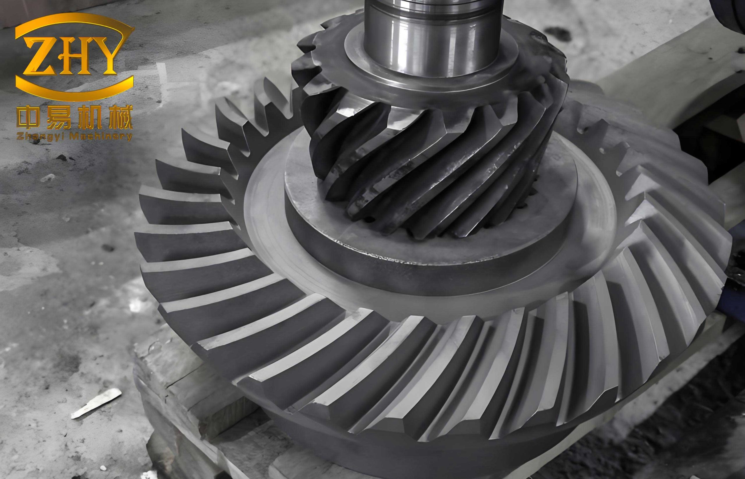
Our initial approach to control deformation in helical bevel gears focused on modifying the furnace loading method. Recognizing that press quenching is a standard industry method but unavailable in our facility, we devised a scheme where two helical bevel gears were placed back-to-back (face-to-face) and fastened together using three bolts through existing mounting holes. The idea was that the two helical bevel gears would mutually constrain each other’s deformation during the heat treatment cycle. The loading configuration is schematically represented (though not using the original image reference). Four helical bevel gears, labeled 1# to 4#, were processed using this method. The heat treatment cycle involved carburizing at 930±10°C to achieve the required case depth, followed by slow cooling, then reheating for quenching (a double quenching process). The results, however, were unsatisfactory. All four helical bevel gears exhibited planar warping exceeding 0.60 mm, far beyond the 0.2 mm limit. The data is summarized in Table 1.
| Helical Bevel Gear Sample ID | Planar Warping (mm) |
|---|---|
| 1# | 0.70 |
| 2# | 0.85 |
| 3# | 0.71 |
| 4# | 0.65 |
The failure of this method was analyzed comprehensively. First, the bolts used for fastening, made of standard steel, experienced significant creep at the high carburizing temperature of 930°C. Creep is the time-dependent plastic deformation of materials under constant stress at elevated temperatures. The bolt stress relaxation reduced the clamping force, allowing the helical bevel gears to move relative to each other. Secondly, the double quenching process itself introduces additional thermal cycles, each exacerbating distortion. Thirdly, and most importantly, the back-to-back arrangement created an asymmetric heating and cooling environment. The contacting large planar faces (the backs) had impeded heat transfer compared to the exposed front faces and the gear teeth. This asymmetry in thermal gradients led to non-uniform phase transformation, amplifying warping. Specifically, the thinner rim section (C) of each helical bevel gear, being more exposed, cooled faster and transformed to martensite first. This early transformation generated stresses that caused the entire gear to warp, as the thicker hub section (A) was still austenitic. The mutual constraint intended by bolting was ineffective due to bolt creep and the inherent asymmetry.
Following this, we designed and implemented a dedicated fixture (special tooling) to better control the deformation of the helical bevel gear. The fixture was a robust, thermally stable plate or structure that allowed the helical bevel gear to be firmly clamped using multiple fasteners. Instead of three bolts, we employed twelve high-strength bolts (model GB5781-86, M16×60) arranged symmetrically around the gear’s mounting flange. The fixture itself had substantial mass and thermal inertia to help moderate temperature gradients. Furthermore, we revised the heat treatment cycle from a double quench to a direct quench process. Direct quenching after carburizing involves cooling the part from the carburizing temperature to the quenching temperature and then immersing it in oil, eliminating the intermediate cooling and reheating steps. This reduces the total thermal cycles and associated distortion. The process parameters were set as: carburizing at (930±10)°C until the desired case depth was achieved, followed by furnace cooling to 790°C (a temperature just above the martensite start temperature for this steel to minimize thermal stress), and then oil quenching to room temperature. Four new helical bevel gear samples, labeled 5# to 8#, were processed using this dedicated fixture and direct quench method. The results were markedly improved, as shown in Table 2.
| Helical Bevel Gear Sample ID | Planar Warping (mm) | Surface Hardness (HRC) | Case Depth (mm) |
|---|---|---|---|
| 5# | 0.18 | 60 | 1.05 |
| 6# | 0.15 | 59 | 0.95 |
| 7# | 0.20 | 61 | 1.00 |
| 8# | 0.12 | 60 | 0.98 |
All helical bevel gears met the technical specifications for hardness, case depth, and critically, planar warping was ≤0.2 mm. The success of this approach can be attributed to several factors. The dedicated fixture with twelve symmetrically placed bolts provided a much more uniform and sustained clamping force. Even if minor creep occurred, the sheer number of bolts and the fixture’s own weight maintained alignment. The fixture also acted as a heat sink, moderating the cooling rate of the clamped face (face A, the mounting face), thereby reducing the temperature difference between face A and the opposite face/rim (face C). This moderation helped synchronize the martensitic transformation between the thick and thin sections. In essence, the fixture slowed down the cooling of section A relative to section C, allowing them to transform closer in time, minimizing the transformational stress mismatch. The direct quenching process further reduced overall thermal exposure and distortion.
To quantitatively understand the effect of the fixture, we can model the heat transfer. During quenching, the cooling rate $\frac{dT}{dt}$ at a point is governed by the heat transfer coefficient $h$ and the temperature difference with the quenchant. For an unclamped face exposed directly to oil, $h$ is high. For the face clamped to the fixture, the effective cooling is slower due to the thermal contact resistance $R_c$ and the fixture’s mass. The temperature evolution can be described by the heat conduction equation with boundary conditions. For the clamped region, a simplified model gives a lower effective heat flux. This reduces the thermal stress component. More importantly, it delays the martensite start time $t_{Ms}$ in the hub region. The time for a location to reach the martensite start temperature $M_s$ can be estimated from cooling curves. If $t_{Ms}^{A}$ for section A is delayed closer to $t_{Ms}^{C}$ for section C, the strain mismatch $\Delta \varepsilon_{tr}$ is reduced. The resulting bending moment $M$ is proportional to this mismatch integrated over the volume. Therefore, controlling the cooling asymmetry is key for the helical bevel gear.
Further refinement involved optimizing the carburizing and quenching parameters themselves. For the material 20Cr2Ni4A, the martensite start temperature $M_s$ is around 300-350°C. Quenching from 790°C, as we did, ensures the part is fully austenitic but minimizes the temperature difference with the quenchant, reducing thermal shock. The cooling curve can be analyzed using CCT (Continuous Cooling Transformation) diagrams. The goal is to achieve full martensite transformation while minimizing temperature gradients. The oil quench medium provides a less severe cooling rate than water, which is beneficial for reducing thermal stress but sufficient to bypass pearlite and bainite formation for this alloy. The case depth control is achieved by adjusting carburizing time using the diffusion equation. For a constant surface carbon concentration $C_s$ and initial carbon $C_0$, the case depth $d$ as the depth where carbon reaches a certain level $C_d$ is approximately given by:
$$ d = k \sqrt{t} $$
where $t$ is time and $k$ is a constant dependent on temperature and diffusivity. We carefully controlled time to achieve 0.8-1.1 mm depth.
The success of our method for the helical bevel gear has broader implications. The principle of using symmetric, multi-point clamping with a massive fixture to control cooling asymmetry and transformational sequence can be applied to other asymmetric components. Additionally, the shift from double quenching to direct quenching, where material science permits, is a general distortion-reduction strategy. For high-alloy steels like 20Cr2Ni4A, direct quenching is often feasible because the high hardenability allows martensite formation even at moderately slow cooling rates from the carburizing temperature. This eliminates the distortion from a second austenitization cycle.
In conclusion, through systematic investigation, we have developed an effective methodology to control deformation in helical bevel gears during carburizing and quenching. The combination of a specially designed multi-bolt fixture and a direct quenching process after carburizing successfully addressed the planar warping issue, bringing deformation within the strict 0.2 mm tolerance. This approach leverages the principles of stress engineering by managing thermal gradients and synchronizing phase transformations. The helical bevel gears produced using this method consistently meet all mechanical property requirements, eliminating the need for costly and risky straightening operations, and thereby improving productivity and yield. Future work may involve finite element simulation to optimize fixture design and quench protocols for different sizes and geometries of helical bevel gears, further advancing the reliability and precision of these critical transmission components.