
In the realm of mechanical power transmission, the health and longevity of gear systems are paramount. Among the various failure modes, adhesive wear on tooth surfaces stands as a predominant and insidious process, gradually degrading performance and ultimately leading to system failure. This is particularly critical in applications involving low-speed, high-torque conditions, such as in heavy-duty vehicle transmissions, wind turbine gearboxes, and certain industrial machinery. At low speeds, the formation of a protective elastohydrodynamic lubrication (EHL) film is often insufficient, forcing gear teeth to operate predominantly in boundary or mixed lubrication regimes. In such states, surface asperities make direct contact, leading to increased friction and a significantly higher propensity for adhesive wear. This wear alters the perfect involute profile, disrupts load distribution, increases noise and vibration, and reduces transmission accuracy and efficiency. Therefore, developing a robust predictive model for adhesive wear under these challenging conditions is not merely an academic exercise but a practical necessity for enhancing reliability and enabling condition-based maintenance. In this article, we present a detailed, integrated methodology for calculating the evolution of adhesive wear on involute cylindrical spur gear pairs, with a specific focus on the interaction between the worn tooth profile and the dynamic load sharing between meshing teeth.
The core of our approach lies in coupling two fundamental models: a modified load distribution model that accounts for progressive profile change due to wear, and the classic Archard wear equation. Traditional analysis often assumes a fixed load-sharing ratio, typically splitting the load equally between two pairs of teeth in the double-contact zone. However, as wear progresses, material is removed non-uniformly from the tooth flanks, creating a form of profile error. This error changes the kinematic relationship and contact timing between meshing teeth, thereby altering how the total load is distributed between concurrent contact points. Ignoring this feedback loop between wear and load distribution can lead to significant inaccuracies in long-term wear prediction.
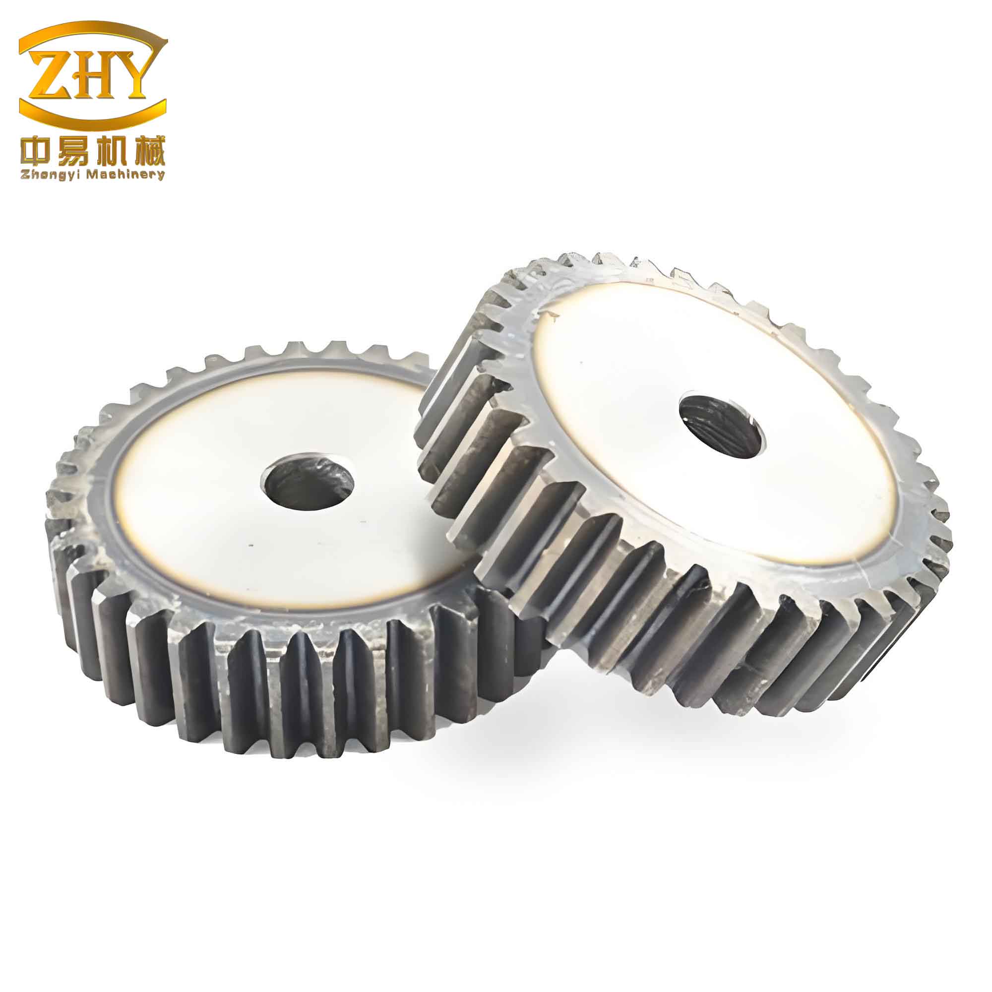
To accurately capture this interaction, we consider the gear mesh along the line of action. For a spur gear pair, the meshing process alternates between single-pair and double-pair contact zones. When two pairs of teeth are in contact, the compatibility of deformations must be satisfied. The difference in the total approach (elastic deformation + wear depth) between the first and second contacting tooth pairs determines how the load is partitioned. Let $h_{w}^{ij}$ represent the wear depth on tooth $i$ of gear $j$. For a two-pair contact scenario, the deformation difference $\tilde{E}_h$ is a function of the cumulative wear at all four contacting surfaces:
$$
\tilde{E}_h = h_{w}^{2g} + h_{w}^{2p} – h_{w}^{1g} – h_{w}^{1p}
$$
where superscripts $p$ and $g$ denote the pinion (driver) and the gear (driven), respectively, and numerals 1 and 2 refer to the first and second tooth pair in contact sequence. The load $F_i$ on tooth pair $i$ is related to its deformation $\delta_i$ and its mesh stiffness $k_i$, which itself is a function of the angular position $\theta$ and the deformation: $k_i = k_i(\theta, \delta_i)$. The total transmitted load $F_T$ is the sum of the loads on both pairs. From force equilibrium and deformation compatibility, the Load Sharing Factor (LSF) for the first tooth pair can be derived as:
$$
LSF_1 = \frac{F_1}{F_T} = \frac{k_1}{k_1 + k_2} \left(1 + \frac{k_2 \tilde{E}_h}{F_T}\right)
$$
Conversely, for the second pair:
$$
LSF_2 = \frac{F_2}{F_T} = \frac{k_2}{k_1 + k_2} \left(1 – \frac{k_1 \tilde{E}_h}{F_T}\right)
$$
These equations clearly show that the load sharing is dynamic and directly influenced by the wear-induced profile errors $\tilde{E}_h$. At the start of life ($\tilde{E}_h = 0$), the load is shared according to the ratio of mesh stiffnesses. As wear accumulates asymmetrically, the load distribution shifts, typically relieving load from the more severely worn pair in one double-contact zone and increasing it on the other. This model forms the critical first pillar of our integrated wear prediction framework.
The second pillar is the wear calculation itself, governed by the Archard wear law. This fundamental model states that the volumetric wear is proportional to the normal load and the sliding distance, and inversely proportional to the hardness of the softer material. For incremental analysis, it is more convenient to work with wear depth. The generalized Archard equation for a point on the tooth surface is:
$$
\frac{dh}{ds} = k \cdot p
$$
Here, $dh$ is the incremental wear depth, $ds$ is the incremental sliding distance, $p$ is the contact pressure, and $k$ is the dimensional wear coefficient. For computational implementation, we use a discrete “single-point observation” method. The wear depth $h_{w}^{P}(n)$ at a specific point $P$ after $n$ meshing cycles is updated each cycle by the incremental wear $\Delta h_{w}^{P}(n)$:
$$
h_{w}^{P}(n+1) = h_{w}^{P}(n) + \Delta h_{w}^{P}(n) = h_{w}^{P}(n) + k_w \cdot p_P(n) \cdot s_P
$$
In this formula, $k_w$ is the non-dimensional wear factor, which is a crucial parameter encapsulating the effects of material properties, lubrication condition, and surface roughness. $p_P(n)$ is the contact pressure at point $P$ during cycle $n$, and $s_P$ is the total sliding distance experienced by that point during one engagement. To solve this equation, we need to determine three key quantities for every point along the path of contact: the contact pressure $p_P$, the sliding distance $s_P$, and the wear factor $k_w$.
The contact between spur gear teeth is typically modeled as an equivalent contact between two cylinders. The radii of these cylinders are equal to the radii of curvature of the involute profiles at the point of contact. For a pinion with pitch diameter $d_{0p}$ and a gear with pitch diameter $d_{0g}$, operating at standard pressure angle $\alpha_0$, the radii of curvature $\rho_1$ and $\rho_2$ at a distance $y$ from the pitch point are:
$$
\rho_1 = \frac{d_{0p}}{2} \sin\alpha_0 + y, \quad \rho_2 = \frac{d_{0g}}{2} \sin\alpha_0 – y
$$
The equivalent radius of curvature $\rho$ is given by $\frac{1}{\rho} = \frac{1}{\rho_1} + \frac{1}{\rho_2}$. Assuming line contact and applying Hertzian theory, the half-width $a_H$ of the contact zone and the pressure distribution $p(x)$ across it can be calculated. The maximum pressure $p_0$ and the pressure at any distance $x$ from the centerline are:
$$
a_H = \sqrt{\frac{4 F_P \rho}{\pi b E^*}}, \quad p(x) = p_0 \sqrt{1 – \left(\frac{x}{a_H}\right)^2}, \quad \text{where} \quad p_0 = \sqrt{\frac{F_P E^*}{\pi b \rho}}
$$
Here, $F_P$ is the normal load on the tooth pair (from the LSF model), $b$ is the face width, and $E^*$ is the equivalent elastic modulus, calculated from the Young’s moduli $E_1, E_2$ and Poisson’s ratios $\nu_1, \nu_2$ of the pinion and gear materials: $\frac{1}{E^*} = \frac{1-\nu_1^2}{E_1} + \frac{1-\nu_2^2}{E_2}$. For wear depth calculation, we often use the maximum pressure $p_0$ as a representative value for the contact patch.
The sliding distance $s_P$ is fundamentally linked to the kinematics of the gear mesh. The two contacting points on the pinion and gear tooth have different tangential velocities, $U_1$ and $U_2$, leading to relative sliding. For a point on the pinion surface, the sliding distance accumulated as it traverses the entire contact zone of half-width $a_H$ is:
$$
s_{P1} = 2a_H \left( \frac{U_1 – U_2}{U_1} \right)
$$
Similarly, for the mating point on the gear tooth:
$$
s_{P2} = 2a_H \left( \frac{U_2 – U_1}{U_2} \right)
$$
The velocities are $U_1 = \omega_1 \rho_1$ and $U_2 = \omega_2 \rho_2$. It is crucial to note that at the pitch point, where $\rho_1 / \rho_2 = \omega_2 / \omega_1$, we have $U_1 = U_2$, resulting in pure rolling and zero sliding distance. This explains the characteristic “zero wear” region observed around the pitch line in gears.
The most complex and variable parameter is the wear factor $k_w$. It is not a material constant but a system property heavily dependent on the lubrication regime. We adopt a model that relates $k_w$ to the specific film thickness $\lambda$, defined as the ratio of the minimum EHL film thickness $h_{min}$ to the composite surface roughness $R_{a,rms}$. The relationship proposed by Priest and Taylor is widely used:
$$
k_w(\lambda) =
\begin{cases}
k_{w0}, & \lambda < 0.5 \quad \text{(Boundary Lubrication)} \\[6pt]
k_{w0} \cdot \dfrac{2(4-\lambda)}{7}, & 0.5 \leq \lambda \leq 4 \quad \text{(Mixed Lubrication)} \\[6pt]
0, & \lambda > 4 \quad \text{(Full-Film EHL Lubrication)}
\end{cases}
$$
Here, $k_{w0}$ is the wear factor under severe boundary lubrication conditions. For low-speed applications, the dimensionless speed parameter $U_w$ is very small, leading to a very small calculated $h_{min}$ from classical EHL formulas (e.g., Dowson-Higginson). Consequently, $\lambda$ often falls well below 0.5, placing the gear pair firmly in the boundary lubrication regime where $k_w = k_{w0}$ is a valid assumption.
Even $k_{w0}$ is not a simple constant. Janakiraman et al. performed a statistical analysis and proposed a fitting formula that relates $k_{w0}$ to operating conditions:
$$
k_{w0} = 3.981 \times 10^{29} \cdot L_w^{1.219} \cdot G_w^{-7.377} \cdot S_w^{1.589} \cdot E’
$$
where $L_w$, $G_w$, and $S_w$ are the dimensionless load, material, and roughness parameters, respectively, and $E’ = 2E^*$ is the plane strain modulus. $L_w = F_P/(b E’ \rho)$, $G_w = \alpha E’$ (with $\alpha$ being the pressure-viscosity coefficient), and $S_w = R_{a,rms}/\rho$. This formulation explicitly shows that $k_{w0}$, and thus the wear factor $k_w$, depends on the local load $F_P$, the curvature $\rho$, and the surface roughness. Therefore, it varies along the path of contact and also evolves as wear changes the surface roughness and load distribution.
To implement the complete wear prediction model, we follow an iterative numerical procedure. The geometry and operating parameters of the spur and pinion gear set are defined. A typical set used for validation is shown in the table below.
| Parameter | Symbol | Value |
|---|---|---|
| Number of teeth (Pinion/Gear) | $z_p / z_g$ | 16 / 24 |
| Module | $m$ | 4.5 mm |
| Pressure Angle | $\alpha_0$ | 20° |
| Face Width | $b$ | 14 mm |
| Young’s Modulus | $E$ | 210 GPa |
| Poisson’s Ratio | $\nu$ | 0.3 |
| Pinion Speed | $n_p$ | 100 rpm |
| Pinion Torque | $T_p$ | 302 Nm |
| Surface Roughness, RMS | $R_{a,rms}$ | 0.3 µm |
The path of contact is discretized into a fine grid of points. For each meshing cycle (or block of cycles for computational efficiency), the following steps are executed:
- Load Distribution Calculation: Using the current wear profile $h_w$ for all teeth, calculate the load sharing factors $LSF_1$ and $LSF_2$ for each position in the double-contact zones using the compatibility equations. In single-contact zones, $LSF=1$.
- Tooth Pair Load Calculation: The load on each individual tooth pair $F_P$ at each contact position is $F_T \cdot LSF$.
- Contact Mechanics: For each contact position, calculate the Hertzian contact pressure $p_0$ and the half-width $a_H$ based on $F_P$ and the local radius of curvature.
- Sliding Distance: Compute the sliding distances $s_{P1}$ and $s_{P2}$ for the corresponding points on the pinion and gear.
- Wear Factor: Determine the local wear factor $k_w$, which for low-speed boundary lubrication is primarily $k_{w0}$ from the empirical formula, a function of the local $F_P$ and $\rho$.
- Wear Increment: Calculate the incremental wear depth for each point on both the pinion and gear: $\Delta h_w = k_w \cdot p_0 \cdot s_P$.
- Profile Update: Add the incremental wear to the cumulative wear depth map of the tooth flanks.
- Iteration: Repeat steps 1-7 for the next meshing cycle. The updated wear profile from the previous cycle feeds into the load distribution calculation of the next, creating the coupled feedback loop.
To validate the proposed integrated model, we compare its predictions with published experimental data. The experiment, conducted by Flodin, involved a spur gear pair with parameters similar to those in the table above, running under lubricated conditions. The key result was the measurement of wear depth at the root of the pinion teeth over a large number of cycles. Our simulation captures the trend remarkably well. In the initial “running-in” phase, the experimental wear rate is slightly higher, which can be attributed to factors like the absence of specific lubricant additives in the test or initial surface asperity removal, which our model simplifies. As the simulation progresses, the predicted wear evolution aligns closely with the experimental data, confirming that the core physics of the wear process, especially the coupling between wear and load sharing, is accurately represented. This validation gives us confidence in using the model to explore the detailed wear behavior of the spur and pinion system.
Now, let us delve into the detailed results and analysis provided by the simulation. The first critical observation is the dynamic evolution of the Load Sharing Factor (LSF). The following table summarizes how LSF changes in the double-contact zones as wear accumulates, contrasting it with the initial, unworn state assumption of equal load sharing.
| Contact Zone | Initial State (No Wear) | Trend with Increasing Wear | Physical Reason |
|---|---|---|---|
| Pinion Root / Gear Tip Zone | ~0.5 (Equal sharing) | Load on this pair decreases | Severe wear at pinion root increases $\tilde{E}_h$, relieving load from this pair. |
| Pinion Tip / Gear Root Zone | ~0.5 (Equal sharing) | Load on this pair increases | Corresponding to the decrease in the first zone, more load is shifted to this pair. |
This shift is not linear but evolves with the wear profile. Consequently, the wear factor $k_w$, being dependent on load $F_P$ via the $k_{w0}$ formula, also changes dynamically along the path of contact. Initially, $k_w$ is higher in the single-pair contact region due to the higher load ($F_P = F_T$). As wear progresses, the load increases in the second double-contact zone (near the pinion tip), causing a local increase in $k_w$ there, while it decreases slightly in the first double-contact zone (near the pinion root) where the load is shed.
The most insightful result is the spatial distribution of cumulative wear depth on the tooth flanks of the spur and pinion. The simulation reveals several hallmark features of gear adhesive wear:
- Zero Wear at the Pitch Point: A region around the pitch line exhibits negligible wear. This is a direct consequence of kinematics: the sliding distance $s_P$ is zero at the pitch point and very small in its immediate vicinity, as shown by the sliding distance equations. With no sliding, the Archard wear rate is essentially zero, regardless of contact pressure.
- Maximum Wear at the Pinion Root: The most severe wear consistently occurs near the root of the driving pinion. This region combines several adverse factors: it is often in the double-contact zone but experiences high sliding distances (as the contact point is far from the pinion’s pitch point), and initially high contact pressure. Although our model shows load shedding from this zone over time, the initial high wear rate sets a deep wear scar that defines the failure profile.
- Maximum Wear at the Gear Tip: Correspondingly, the maximum wear on the driven gear occurs near its tip, which is the mating region to the pinion root.
- Wear Step at the Single/Double Pair Contact Transition: A distinct step or discontinuity in wear depth is observed at the transition point from double-pair to single-pair contact (Point A in the engagement cycle). This is a direct result of the sudden change in load on the tooth pair. In the double-contact zone just before Point A, the tooth pair carries only a fraction of $F_T$ (e.g., ~40%). Immediately after Point A, as it becomes the sole contacting pair, its load jumps to $F_T$. This instantaneous doubling (or more) of load causes a corresponding jump in the wear increment per cycle at that specific location, etching a step into the wear profile.
The interplay between the spur gear and the pinion is asymmetric due to their different number of teeth and hence different radii of curvature. The pinion, being smaller, experiences more meshing cycles per revolution and typically has higher curvature at the contact point (smaller $\rho_1$), leading to higher contact pressure for the same load. This makes the pinion the more critical component from a wear life perspective in a standard reduction gearset.
In conclusion, we have developed and validated a comprehensive model for predicting adhesive wear in involute cylindrical spur and pinion gears operating under low-speed, boundary-lubrication conditions. The model’s principal strength is the integration of a dynamic load-sharing algorithm that responds to the evolving tooth profile from wear, with a physics-based Archard wear calculation that incorporates variable contact pressure, sliding distance, and a lubrication-regime-dependent wear factor. This coupling is essential for accurate long-term wear prediction, as it captures the fundamental feedback mechanism where wear alters load distribution, which in turn modifies future wear rates.
Our analysis, enabled by this model, confirms and quantifies key wear characteristics: the existence of a zero-wear pitch region, the localization of maximum wear at the pinion root (and gear tip), and the formation of wear steps at meshing transition points. These insights are crucial for design engineers. They highlight critical areas for potential design interventions, such as targeted profile modifications (tip and root relief) to mitigate the load steps and redistribute stress, or the application of specialized surface treatments and coatings on the pinion flanks to enhance wear resistance precisely where it is needed most. Furthermore, this model serves as a foundational tool for predicting the functional life of gear transmissions in demanding low-speed applications, allowing for more reliable maintenance scheduling and preventing unexpected failures. Future work could extend this framework to include the effects of mild abrasive wear from contaminants, the evolution of surface roughness during running-in, and the transition into more severe failure modes like scuffing.