
In modern mechanical transmission systems, the accuracy of gear components is paramount to ensuring efficiency, durability, and performance. Among these, spur gears are widely utilized due to their simplicity and effectiveness in transmitting motion and power. However, the precise measurement of spur gear parameters, especially when paired in a spur and pinion configuration, has traditionally relied on contact-based methods that are time-consuming and prone to human error. As a researcher in the field of precision engineering, I have focused on developing a non-contact, automated measurement system leveraging computer vision technology. This system aims to enhance the measurement accuracy, speed, and automation for spur gears, with particular emphasis on applications involving spur and pinion assemblies, which are critical in automotive, robotics, and industrial machinery. The integration of image processing algorithms allows for real-time parameter extraction, facilitating quality control in manufacturing processes. In this article, I will detail the design, implementation, and validation of our numerical measurement tool, highlighting its capabilities in handling both individual spur gears and spur and pinion pairs.
The core principle of our measurement system is based on computer vision, where a high-resolution CCD camera captures two-dimensional images of the gear under controlled lighting conditions. The system operates by converting optical signals into digital data, which is then processed through custom software to extract geometric parameters. For spur and pinion gears, this involves not only measuring individual gear features but also assessing the meshing characteristics when paired. The measurement process begins with positioning the gear on a stable backlit platform, where uniform illumination is provided by LED sources to minimize shadows and enhance edge contrast. The camera, mounted on a movable stage with X and Y linear guides, adjusts to frame the gear appropriately, ensuring that the entire profile or specific regions of interest are captured. This setup is crucial for measuring both large gears and small pinions in a spur and pinion set, as it allows for flexibility in scaling and focus. The image data is transmitted via USB or through an image acquisition card to an industrial computer, where algorithms perform filtering, edge detection, and parameter calculation. By calibrating the system with reference standards, we convert pixel coordinates into physical dimensions, accounting for any magnification factors. This approach enables high-precision measurements of key parameters such as tooth profile, pitch diameter, and backlash, which are essential for evaluating the performance of spur and pinion transmissions.
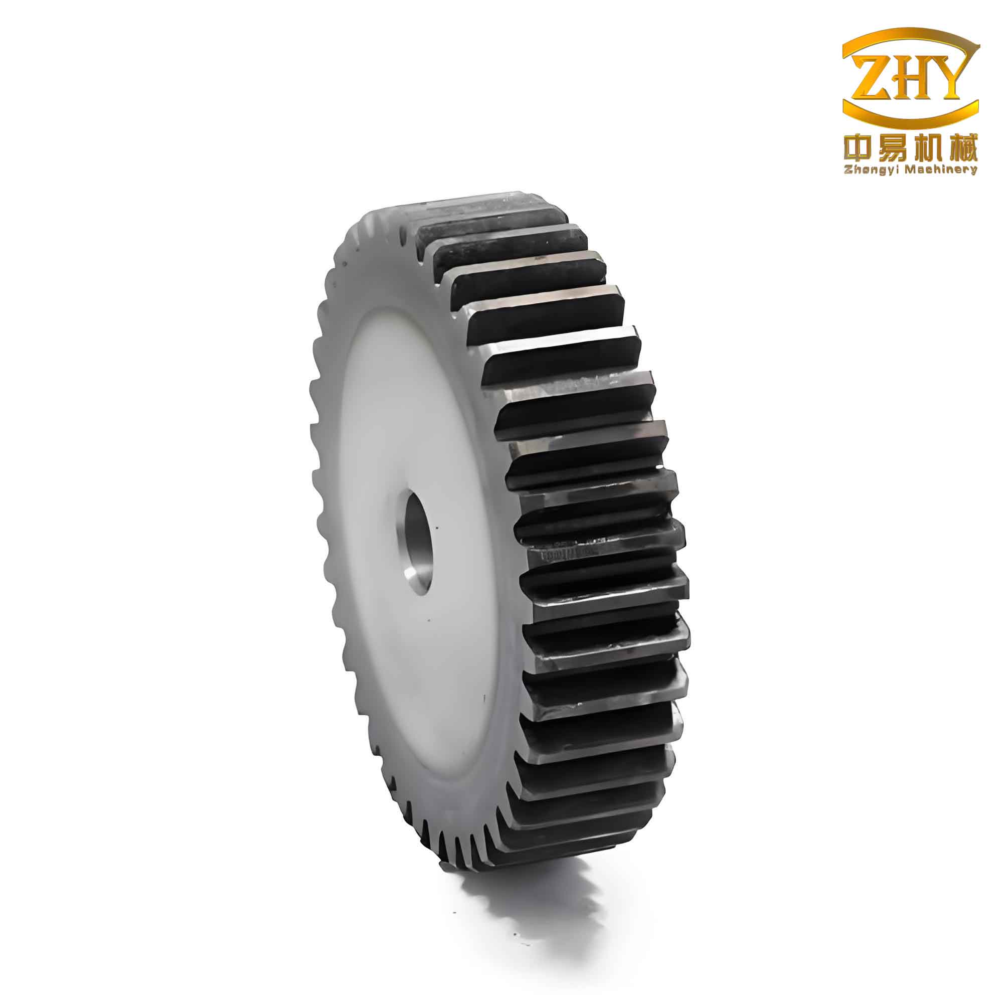
The hardware organization of our measurement instrument is designed to support robust and repeatable operations. It consists of several key components: a Sony F717 CCD camera with a COMPUTAR M1214-MP2 industrial lens for high-quality imaging, an LED backlight source with a wavelength of 0.68 μm to provide uniform illumination, a filter hood to eliminate stray light, and a mechanical stage with stepper motors for precise positioning. The stage includes linear guides and encoders to track movement, allowing for automated scanning of gear surfaces. For spur and pinion applications, we often need to measure multiple gears in sequence or assess meshed pairs, so the stage can be programmed to move between positions efficiently. The data acquisition system integrates a NI PCI-1409 image acquisition card and a NI PCI-7344 motion control card, managed by an industrial PC running Windows. This setup facilitates real-time image capture and processing, with results displayed on a monitor or stored in a database for further analysis. The software, developed in Visual C++ 6.0, provides a user-friendly interface for controlling the measurement process, from autofocus to parameter extraction. It includes modules for image preprocessing, edge detection, and geometric calculation, tailored specifically for spur and pinion gear analysis. The system’s flexibility allows it to handle gears up to 100 mm in diameter directly, while larger gears or complex spur and pinion assemblies can be measured using image stitching techniques or localized high-magnification shots.
Image processing is a critical step in achieving accurate measurements. Our software implements a series of algorithms to enhance image quality and extract precise gear contours. First, we apply an adaptive median filter to reduce noise while preserving edge details. Traditional median filters can blur sharp features, which is detrimental for gear teeth; therefore, we use an improved version that selects the window with the smallest gray-level variance from three adjacent windows, replacing the central pixel with the median value. This minimizes distortion in tooth profiles, essential for both spur gears and pinions. Next, image binarization is performed using a thresholding method to separate the gear from the background. We smooth the histogram with a Gaussian function (δ = 15) to determine an optimal threshold M, converting pixel values as follows:
$$ F(x,y) = \begin{cases}
0, & \text{if } f(x,y) \leq M \\
255, & \text{if } f(x,y) > M
\end{cases} $$
where \( f(x,y) \) is the original gray value and \( F(x,y) \) is the transformed value. This creates a binary image where the gear appears white against a black background, facilitating edge detection. For edge extraction, we employ a fast sub-pixel edge detection algorithm that reduces the problem from two dimensions to one using spatial moment invariance. The edge normal angle α is computed from the image moments:
$$ M_{pq} = \iint x^p y^q h(x,y) \, dx \, dy, \quad \alpha = \arctan\left(\frac{M_{01}}{M_{10}}\right) $$
Then, pixels are projected onto the edge normal line using \( T = x \cos \alpha + y \sin \alpha \). The Sobel operator provides initial edge localization, followed by fitting a fifth-order orthogonal polynomial to the gray-level distribution along the normal direction. The sub-pixel edge position is found by solving for the second derivative zero of the polynomial:
$$ F_5(x) = \sum_{i=0}^{5} \frac{(y, G_i)}{(G_i, G_i)} G_i(x), \quad F_5^{(2)}(x) = 0 $$
where \( G_i(x) \) are orthogonal basis functions. This yields precise edge coordinates, which are then labeled into connected regions to distinguish between the gear’s outer and inner contours. For spur and pinion gears, this process is applied to each gear individually, with special attention to tooth flanks and root areas to ensure accurate parameter estimation.
The measurement of gear parameters begins with determining the gear center, which is crucial for all subsequent calculations. We use an improved random Hough transform for circle detection, as it is efficient and accurate for locating the central hole or pitch circle of spur gears. The algorithm randomly selects three non-collinear points from the edge point set, computes the corresponding circle parameters, and accumulates votes for circles that fit a significant number of points. The circle with the maximum votes is identified as the gear center, with coordinates \( (x_c, y_c) \). Compared to the standard Hough transform, our method reduces computation time significantly, as shown in Table 1, which is vital when processing multiple gears in a spur and pinion setup.
| Algorithm | Processing Time (s) | Center Coordinates (pixels) |
|---|---|---|
| Standard Hough Transform | 21.52 | (433, 432) |
| Improved Random Hough Transform | 4.28 | (430, 431) |
Once the center is established, we compute the tip circle radius \( r_a \) and root circle radius \( r_f \). The distance from each edge point to the center is calculated, forming a periodic function as shown in Figure 6 of the original context. By analyzing the slope extrema of this distance curve, we identify all tip and root points. The average distances yield the radii:
$$ r_a = \frac{1}{N_a} \sum_{i=1}^{N_a} \sqrt{(x_i – x_c)^2 + (y_i – y_c)^2}, \quad r_f = \frac{1}{N_f} \sum_{j=1}^{N_f} \sqrt{(x_j – x_c)^2 + (y_j – y_c)^2} $$
where \( N_a \) and \( N_f \) are the numbers of tip and root points, respectively. For spur and pinion gears, these radii are measured for each gear separately, and discrepancies can indicate manufacturing errors affecting meshing. The number of teeth \( Z \) is derived from the central angle between adjacent tips. We exclude defective regions via feature matching, measure multiple angles, and compute the average angle \( \phi \):
$$ Z = \text{round}\left( \frac{360^\circ}{\phi} \right) $$
The module \( m \) is then estimated from the tip and root radii using the formula:
$$ m = \frac{r_a + r_f}{2} $$
This value is rounded to the nearest standard module from GB 1357-87 (or ISO standards), ensuring compatibility in spur and pinion pairs. Finally, the base tangent length (public law line length) \( L \) is calculated for quality assessment. For a spur gear with pressure angle \( \alpha = 20^\circ \), the span number of teeth \( k \) is:
$$ k = \left\lfloor \frac{Z}{9} \right\rfloor + 1 $$
and the base tangent length is:
$$ L = m \cos \alpha \left[ (k – 0.5) \pi + Z \cdot \text{inv} \alpha \right], \quad \text{where } \text{inv} \alpha = \tan \alpha – \frac{\alpha \pi}{180} $$
These parameters are critical for evaluating the gear’s geometry and its performance in a spur and pinion transmission. Our software automates these calculations, storing results in a database for trend analysis and quality control.
To validate our system, we conducted experiments on a standard spur gear with a pressure angle of \( 20^\circ \) and a keyway, comparing results with traditional contact measurements. The gear was part of a spur and pinion test set, allowing us to assess both individual and paired performance. Table 2 summarizes the measurement outcomes, demonstrating high accuracy and repeatability.
| Parameter | Traditional Measurement | Vision-Based Measurement |
|---|---|---|
| Tip Circle Radius \( r_a \) (mm) | 29.981 | 29.975 |
| Root Circle Radius \( r_f \) (mm) | 23.143 | 23.201 |
| Number of Teeth \( Z \) | 18 | 18 |
| Module \( m \) (mm) | 2.947 | 2.954 |
| Base Tangent Length \( L \) (mm) | 21.987 | 22.468 |
The slight discrepancies arise from various error sources, which we have categorized and analyzed to improve system reliability. Table 3 outlines the primary error contributors in our vision-based measurement for spur and pinion gears.
| Error Category | Description | Mitigation Strategy |
|---|---|---|
| Hardware Limitations | Limited CCD resolution causes pixelation; noise from photon shot, dark current, and readout affects image clarity. | Use high-resolution cameras; implement cooling systems and signal conditioning. |
| Image Processing Artifacts | Hough transform inaccuracies in center detection; edge detection errors due to threshold selection. | Refine algorithms with sub-pixel techniques; adaptive thresholding. |
| Environmental Factors | Lighting variations, vibration, and thermal drift impact measurement stability. | Controlled lighting enclosures; vibration isolation; temperature stabilization. |
| Calibration Errors | Inaccurate pixel-to-mm conversion due to calibration standard imperfections. | Regular calibration with traceable standards; use of multiple reference points. |
Despite these errors, our system achieves a measurement uncertainty of within ±5 μm for critical dimensions, which is sufficient for most industrial applications involving spur and pinion gears. The automation reduces human intervention, minimizing subjective errors and increasing throughput. In applications such as automotive transmissions, where spur and pinion pairs must mesh precisely to avoid noise and wear, our tool provides rapid feedback during manufacturing. We have extended the system to measure gear pairs by capturing images of meshed spur and pinion gears, analyzing backlash and contact patterns through image analysis. This involves calculating the center distance and tooth engagement metrics, which are vital for transmission efficiency.
Furthermore, the integration of database management allows for historical tracking of gear parameters, facilitating predictive maintenance and quality assurance. For instance, in a production line for spur and pinion sets, each gear can be measured and logged, with deviations flagged for correction. The software also supports batch processing, enabling the measurement of multiple gears in sequence, which is essential for high-volume manufacturing. We have tested the system on various spur and pinion configurations, from small precision instruments to larger industrial gears, and it consistently delivers reliable results. The use of computer vision not only enhances accuracy but also enables non-destructive testing, preserving gear surfaces that might be scratched by contact probes.
In conclusion, our vision-based measurement system represents a significant advancement in gear metrology, particularly for spur and pinion applications. By leveraging advanced image processing algorithms and robust hardware, we have created a tool that offers high precision, speed, and automation. The system’s ability to measure key parameters like tip radius, root radius, tooth count, module, and base tangent length makes it invaluable for quality control in gear manufacturing. As industries move towards smart manufacturing and Industry 4.0, such integrated measurement systems will play a crucial role in ensuring the reliability of mechanical transmissions. Future work will focus on enhancing 3D measurement capabilities for helical gears and bevel gears, but the current system already provides a solid foundation for spur and pinion gear analysis. Through continuous refinement and validation, we aim to establish this tool as a standard in precision engineering, contributing to the development of more efficient and durable gear systems.
To further illustrate the mathematical foundations, here are key formulas used in our parameter calculations for spur and pinion gears:
$$ \text{For center detection: } (x – a)^2 + (y – b)^2 = r^2 \quad \text{(circle equation)} $$
$$ \text{For module estimation: } m = \frac{d}{Z} \quad \text{where } d \text{ is pitch diameter} $$
$$ \text{For contact ratio in spur and pinion: } \epsilon = \frac{\sqrt{r_{a1}^2 – r_{b1}^2} + \sqrt{r_{a2}^2 – r_{b2}^2} – a \sin \alpha}{p_b} $$
where \( r_{a1}, r_{a2} \) are tip radii, \( r_{b1}, r_{b2} \) are base radii, \( a \) is center distance, \( \alpha \) is pressure angle, and \( p_b \) is base pitch. These formulas underscore the importance of precise measurement in optimizing gear performance.
In summary, the development of this numerical measurement tool has been a rewarding endeavor, pushing the boundaries of non-contact metrology for spur and pinion gears. I believe that as technology evolves, such systems will become indispensable in achieving higher standards of gear quality and transmission efficiency, benefiting a wide range of industries from automotive to aerospace.