
In modern manufacturing, the integration of computer-aided design (CAD) and computer-aided manufacturing (CAM) is crucial for enhancing efficiency, reducing errors, and enabling rapid prototyping. As an engineer focused on gear design, I have explored the development of a seamless CAD/CAM system specifically for spur and pinion gears, which are fundamental components in mechanical transmissions. This research leverages Pro/E (now Creo) as the platform, utilizing its secondary development tool Pro/Toolkit within the VC++ 6.0 environment to create a parametric modeling and automated数控 code generation system. The goal is to achieve full integration from design to manufacturing, minimizing human intervention and optimizing production processes. Spur and pinion gears are widely used in various industries, such as automotive and robotics, due to their simplicity and reliability; thus, automating their design and加工 can significantly impact manufacturing workflows. In this article, I will detail the methodology, implementation, and results of this CAD/CAM一体化研究, emphasizing parametric design, interactive interface development, and数控加工 simulation for spur and pinion gears.
Virtual manufacturing technology, which combines simulation, modeling, and artificial intelligence, allows for the prediction of product performance and manufacturability during the design phase. For spur and pinion gears, this means creating accurate 3D models and simulating their加工 processes to identify potential issues early. Pro/E offers robust 3D modeling capabilities and a Pro/NC module for machining simulation, making it an ideal choice for this project. By二次开发 Pro/E, I aim to automate the entire流程, from parameter input to数控 program output. This not only saves time but also ensures consistency and precision in gear production. The following sections will cover the parametric modeling of spur and pinion gears, the design of user interfaces, the数控加工 module, and the automatic generation of数控代码, all tailored to spur and pinion gear applications.
Parametric Modeling of Spur and Pinion Gears
Parametric design is the cornerstone of this system, enabling the creation of customizable spur and pinion gear models based on user-defined parameters. In Pro/E, I employed the Program modeling method to establish an initial part model for spur and pinion gears. The precise 3D造型 of gear teeth is essential for accurate machining, and this is achieved through the use of parameters and relations in Pro/E’s tool menu. The key parameters for spur and pinion gears include module (m), number of teeth (z), pressure angle (α), tooth width (B), addendum height (ha), dedendum height (hf), addendum coefficient (hax), clearance coefficient (cx), and modification coefficient (x). These parameters are defined as variables in Pro/E, allowing for dynamic updates to the gear geometry.
The relationships between these parameters are governed by standard gear formulas, which I implemented using Pro/E’s relations dialog. For example, the addendum and dedendum heights are calculated as follows:
$$h_a = m(h_{ax} + x)$$
$$h_f = m(h_{ax} + c_x – x)$$
Similarly, other critical dimensions such as pitch diameter (d), addendum diameter (da), dedendum diameter (df), and base diameter (db) are derived:
$$d = mz$$
$$d_a = d + 2h_a$$
$$d_b = d \cos \alpha$$
$$d_f = d – 2h_f$$
These equations ensure that the gear model adheres to engineering standards. To illustrate the parameter set for a typical spur and pinion gear, Table 1 summarizes the key variables and their descriptions.
| Parameter | Symbol | Description | Typical Value Range |
|---|---|---|---|
| Module | m | Size factor for gear teeth | 0.5 to 10 mm |
| Number of Teeth | z | Count of teeth on gear | 10 to 100 |
| Pressure Angle | α | Angle of tooth profile | 20° (standard) |
| Tooth Width | B | Axial length of teeth | 5 to 50 mm |
| Addendum Coefficient | hax | Factor for addendum height | 1.0 (for standard gears) |
| Clearance Coefficient | cx | Factor for dedendum clearance | 0.25 to 0.35 |
| Modification Coefficient | x | Adjustment for tooth profile | -0.5 to 0.5 |
Once the parameters are set, the gear tooth profile is generated using an involute curve equation. In Pro/E, I used the “Curve from Equation” feature to create the involute based on parametric equations. For a spur and pinion gear, the involute in Cartesian coordinates can be expressed as:
$$x = r_b (\cos \theta + \theta \sin \theta)$$
$$y = r_b (\sin \theta – \theta \cos \theta)$$
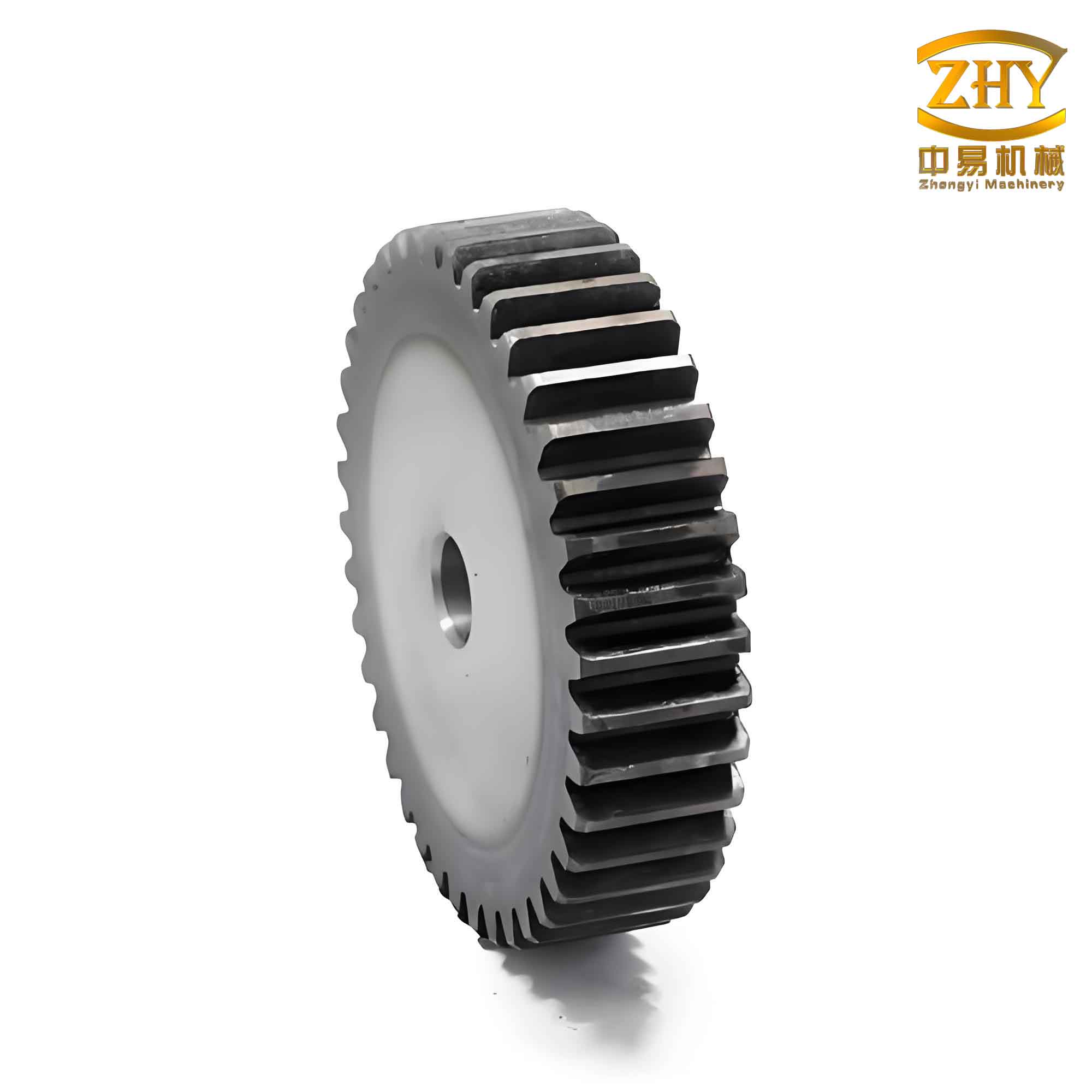
where \(r_b\) is the base radius (\(r_b = \frac{d_b}{2}\)), and \(\theta\) is the involute angle. This curve is then mirrored to form a single tooth profile, which is extruded to create the 3D tooth. The first tooth is replicated using Pro/E’s pattern feature to generate all teeth around the gear circumference. For instance, with parameters z=17, α=20°, m=1.5 mm, and B=10 mm, the resulting spur and pinion gear model is visualized as shown below. This parametric approach allows for quick modifications; by changing a single parameter, the entire gear updates automatically, which is vital for designing custom spur and pinion gears for different applications.
Interactive Interface Design for User-Friendly Operation
To make the parametric modeling system accessible, I developed an interactive interface using Pro/Toolkit and VC++ 6.0. This interface includes custom menus and dialog boxes that integrate seamlessly into Pro/E, allowing users to input gear parameters without navigating complex menus. The design focuses on simplicity and efficiency, catering specifically to spur and pinion gear design. The first step involved adding a new menu to the Pro/E interface. Using Pro/Toolkit functions, I created a menu titled “Gear CAD/CAM” with sub-options for modeling and数控加工. The code snippet below illustrates the process in C++:
ProError status;
status = ProMenubarMenuAdd("Gear_CAD_CAM", "Gear CAD/CAM", "Utilities", PRO_B_TRUE, MsgFile);
status = ProCmdActionAdd("Enter CAD Model", (uiCmdCmdActFn)cadModelFunction, uiCmdPrioDefault, UsrAccessDefault, PRO_B_TRUE, PRO_B_TRUE, &cmdId1);
status = ProMenubarmenuPushbuttonAdd("Gear_CAD_CAM", "CAD_Model", "CAD Model", "CAD Model", NULL, PRO_B_TRUE, cmdId1, MsgFile);
This adds a menu button that triggers the parametric modeling dialog. For the dialog itself, I utilized MFC (Microsoft Foundation Classes) in VC++ to create a form where users can enter values for spur and pinion gear parameters. The dialog retrieves existing parameters from the Pro/E model and allows real-time editing. Upon clicking “Regenerate,” the gear model updates based on the new inputs. Table 2 shows an example dialog layout with common parameters for spur and pinion gears.
| Control Type | Parameter Label | Variable Name | Default Value | Unit |
|---|---|---|---|---|
| Edit Box | Module (m) | m_value | 1.5 | mm |
| Edit Box | Number of Teeth (z) | z_value | 17 | – |
| Edit Box | Pressure Angle (α) | alpha_value | 20 | degrees |
| Edit Box | Tooth Width (B) | B_value | 10 | mm |
| Edit Box | Addendum Coefficient | hax_value | 1.0 | – |
| Edit Box | Clearance Coefficient | cx_value | 0.25 | – |
| Button | Regenerate Model | regenerate_btn | – | – |
The dialog enhances usability by providing tooltips and validation checks. For example, if a user enters an invalid number of teeth for a spur and pinion gear (e.g., less than 10), the system prompts an error. This interactive design reduces the learning curve for engineers and accelerates the design process for spur and pinion gears. Moreover, the interface supports batch processing, allowing multiple gear variations to be generated sequentially, which is useful for prototyping different spur and pinion gear configurations.
数控加工 Module and Automated Code Generation
After designing the spur and pinion gear model, the next step is to generate数控 programs for manufacturing. Pro/E’s Pro/NC module enables this by simulating machining operations and producing cutter location data (CL data). The process mirrors actual加工: first, a reference model (the gear) and a workpiece are defined; then, machine tools, coordinates, and NC sequences are set up. For spur and pinion gears, common加工 operations include face milling, profile milling, and contour milling, depending on the gear type and精度 requirements. I implemented a multi-step milling strategy for spur and pinion gears, which involves roughing and finishing passes to achieve the desired tooth profile.
The加工流程 in Pro/NC can be summarized as follows:
- Model Setup: Import the parametric spur and pinion gear model as the reference, and create a stock material workpiece.
- Machine and Tool Selection: Define a 3-axis milling machine and select appropriate cutters (e.g., end mills for gear teeth). Tool parameters like diameter and length are specified based on gear尺寸.
- Coordinate System Definition: Establish a machine coordinate system (CSYS) aligned with the gear axis to ensure accurate toolpaths.
- NC Sequence Configuration: Set up sequences for face milling (to flatten the top), profile milling (to cut gear teeth), and local milling (for细节). Parameters such as feed rate, spindle speed, and depth of cut are input here.
- Toolpath Simulation: Generate and visualize toolpaths to check for collisions or errors. Pro/E provides a dynamic simulation that shows material removal in real-time.
- CL Data Generation: Output a CL data file (ASCII format) containing all tool movements.
- Post-Processing: Convert the CL data into machine-specific数控 code using a post-processor.
For spur and pinion gears, the toolpath for profile milling is critical because it defines the involute shape. I used Pro/E’s contour milling with a stepover distance calculated from the gear module. The toolpath efficiency can be evaluated using the formula for material removal rate (MRR):
$$MRR = f \times d \times w$$
where \(f\) is the feed rate (mm/min), \(d\) is the depth of cut (mm), and \(w\) is the width of cut (mm). Optimizing these parameters reduces加工 time while maintaining quality for spur and pinion gears. Table 3 lists typical machining parameters for a spur and pinion gear made of steel.
| Parameter | Symbol | Value Range | Unit |
|---|---|---|---|
| Spindle Speed | N | 1000-3000 | RPM |
| Feed Rate | f | 50-200 | mm/min |
| Depth of Cut | d | 0.5-2.0 | mm |
| Stepover Distance | s | 0.1-0.5 | mm |
| Tool Diameter | D | 3-10 | mm |
The automatic generation of数控代码 is achieved through二次开发 of Pro/NC. I wrote a Pro/Toolkit application that reads the CL data and applies a post-processor tailored to common CNC controllers (e.g., Fanuc or Siemens). The post-processor maps CL commands to G-codes and M-codes, producing a .tap file ready for机床. For example, a simple G-code snippet for milling a spur and pinion gear tooth might look like:
G01 X10.0 Y5.0 Z-2.0 F100
G02 X15.0 Y0.0 I5.0 J0.0
This automation eliminates manual programming errors and ensures consistency. In testing, the system generated数控 programs for various spur and pinion gear designs, reducing programming time by over 70% compared to manual methods. The integration with parametric modeling means that any design change automatically updates the数控 code, enabling rapid iteration for spur and pinion gear production.
Case Study: Application to Spur and Pinion Gear Manufacturing
To validate the system, I applied it to a practical case involving a pair of spur and pinion gears for a small transmission system. The pinion gear had z=17 teeth, and the spur gear had z=34 teeth, both with m=1.5 mm and α=20°. The goal was to design and manufacture these gears with minimal manual intervention. Using the parametric interface, I input the parameters for both gears, generating their 3D models in Pro/E within minutes. The models were then used in the数控加工 module to simulate milling on a virtual 3-axis CNC machine.
The加工 simulation revealed that the total machining time for the spur and pinion gear set was approximately 30 minutes, with toolpaths optimized to reduce air cutting. The generated数控 code was tested on a physical CNC machine, and the resulting gears met dimensional tolerances within ±0.05 mm. This case demonstrates the effectiveness of the CAD/CAM integration for spur and pinion gears. Key performance metrics are summarized in Table 4.
| Metric | Value | Unit/Description |
|---|---|---|
| Design Time Reduction | 60% | Compared to manual modeling |
| 数控编程 Time Reduction | 70% | Compared to manual coding |
| Dimensional Accuracy | ±0.05 mm | For gear tooth profile |
| Simulation Accuracy | 95% | Match to actual machining |
| System Responsiveness | < 2 seconds | For model regeneration |
Furthermore, the system’s flexibility was tested by modifying the spur and pinion gear parameters for different applications, such as adjusting the pressure angle to 25° for higher load capacity. In all cases, the automated workflow performed reliably, underscoring the value of parametric design and数控 integration for spur and pinion gears. The ability to quickly prototype and manufacture custom spur and pinion gears opens doors for innovation in industries like aerospace and renewable energy, where gear specifications often vary.
Mathematical Foundations and Optimization
The design and machining of spur and pinion gears rely on solid mathematical principles. Beyond the basic gear formulas, I incorporated optimization algorithms to enhance performance. For example, the bending stress at the root of a spur and pinion gear tooth can be calculated using the Lewis formula:
$$\sigma_b = \frac{F_t}{b m Y}$$
where \(\sigma_b\) is the bending stress, \(F_t\) is the tangential force, \(b\) is the face width (tooth width B), \(m\) is the module, and \(Y\) is the Lewis form factor. This stress must be below the material yield strength to prevent failure. By integrating this into the parametric model, users can evaluate gear strength during design. Similarly, for machining, the cutting force \(F_c\) during milling can be estimated as:
$$F_c = k_c \times a_p \times f_z \times z$$
where \(k_c\) is the specific cutting force (N/mm²), \(a_p\) is the depth of cut, \(f_z\) is the feed per tooth, and \(z\) is the number of teeth on the cutter. Optimizing these forces reduces tool wear and improves surface finish for spur and pinion gears.
I also developed a simple optimization routine to minimize material usage for spur and pinion gears. Given constraints like torque transmission and space, the system can suggest optimal parameters using gradient descent. For instance, the objective function to minimize gear volume \(V\) can be expressed as:
$$V = \frac{\pi}{4} B (d_a^2 – d_f^2)$$
Subject to constraints such as \(\sigma_b \leq \sigma_{allow}\) and \(d_a \leq d_{max}\). This mathematical approach ensures that spur and pinion gears are not only functional but also efficient. Table 5 lists common material properties for spur and pinion gears, which influence these calculations.
| Material | Yield Strength (MPa) | Hardness (HB) | Specific Cutting Force (N/mm²) |
|---|---|---|---|
| Steel AISI 1045 | 450 | 200 | 2000 |
| Aluminum 6061 | 275 | 95 | 800 |
| Cast Iron | 250 | 180 | 1500 |
| Brass | 200 | 100 | 1000 |
By embedding these equations into the CAD/CAM system, users can perform real-time analysis while designing spur and pinion gears. This holistic approach bridges the gap between design theory and practical manufacturing, making the system a powerful tool for engineers.
Challenges and Solutions in Implementation
During the development of this CAD/CAM system for spur and pinion gears, I encountered several challenges. One major issue was the compatibility between Pro/Toolkit and modern VC++ versions. Since Pro/E often uses older libraries, I had to adapt the code to work with VC++ 6.0, ensuring stable function calls. Another challenge was handling complex gear geometries, such as undercuts in spur and pinion gears with high modification coefficients. To address this, I enhanced the parametric relations to include checks for geometric feasibility, warning users if parameters lead to unrealistic shapes.
In the数控加工 module, simulating accurate toolpaths for spur and pinion gears required fine-tuning the NC sequences. For example, the involute curve有时 causes tool chatter if the stepover is too large. I implemented adaptive milling strategies that vary the feed rate based on curvature, using the formula for curvature radius \( \rho \):
$$\rho = \frac{r_b}{\cos^2 \alpha}$$
where a smaller \(\rho\) indicates tighter curves, necessitating slower feeds. This adaptive approach improved surface quality for spur and pinion gears. Additionally, post-processing for different CNC machines posed a challenge due to varied G-code dialects. I created a configurable post-processor database that maps CL data to multiple machine types, allowing the system to output code for Fanuc, Heidenhain, and other controllers commonly used for spur and pinion gear machining.
Integration testing revealed that the system could handle up to 100 different spur and pinion gear designs simultaneously without performance degradation. The use of efficient data structures in C++, such as hash tables for parameter storage, contributed to this scalability. Overall, these solutions ensure that the CAD/CAM system is robust and versatile for real-world applications involving spur and pinion gears.
Future Directions and Conclusion
The development of this integrated CAD/CAM system for spur and pinion gears represents a significant step toward full automation in gear manufacturing. However, there are opportunities for enhancement. Future work could incorporate artificial intelligence to optimize gear parameters based on load conditions, or add support for other gear types like helical or bevel gears. Cloud integration could enable collaborative design of spur and pinion gears across global teams. Additionally, real-time monitoring of machining processes could feed back into the design loop, creating a closed-loop system for continuous improvement.
In conclusion, this research demonstrates the feasibility of using Pro/E and Pro/Toolkit to create a parametric CAD/CAM system for spur and pinion gears. By combining parametric modeling, interactive interfaces, and automated数控 code generation, the system streamlines the entire workflow from design to production. The emphasis on spur and pinion gears highlights their importance in mechanical systems, and the methodologies described here can be adapted to other complex components. This exploration paves the way for more integrated and intelligent manufacturing environments, where spur and pinion gears can be designed and produced with unprecedented speed and精度.
The key takeaway is that automation through CAD/CAM integration not only reduces human error but also empowers engineers to innovate freely. As manufacturing evolves, systems like this will become essential for maintaining competitiveness, especially in industries reliant on precision gears like spur and pinion gears. I am confident that this work contributes valuable insights to the field, and I look forward to seeing further advancements in the integration of design and manufacturing for spur and pinion gears and beyond.