
In mechanical transmission systems, the straight spur gear is widely used due to its simplicity, high efficiency, and ease of manufacture. One of the most critical aspects in gear design is the evaluation of bending strength, which is directly influenced by the geometry of the tooth root transition curve. The International Organization for Standardization (ISO) and the American Gear Manufacturers Association (AGMA) standards both identify the root fillet region as the location of maximum bending stress. A precise determination of the curvature radius along this transition curve is essential for accurate stress analysis and reliable gear design. In this study, we develop a comprehensive analytical method based on the generating motion principle and the theorem of three instantaneous centers to derive an exact expression for the curvature radius at any point on the tooth root transition curve of an involute straight spur gear. We then investigate the effects of key gear parameters—number of teeth, profile shift coefficient, pressure angle, and addendum coefficient—on the minimum curvature radius. The results provide valuable guidance for optimizing gear root geometry to enhance bending strength.
1. Generation of the Tooth Root Transition Curve
The tooth profile of a straight spur gear is typically formed by a hob or rack cutter using the generating (hobbing) process. The cutting tool has a basic rack profile as shown in Figure 1 (not included here), which includes a straight flank for generating the involute tooth flank and a rounded tip that generates the root transition curve. The rack cutter parameters are defined as: module \(m\), pressure angle \(\alpha\), addendum coefficient \(h_a^*\), tip clearance coefficient \(c^*\), and tip radius \(\rho_0\). During the generating motion, the rack translates with velocity \(v_c\) while the gear blank rotates with angular velocity \(\omega\) around its center \(O\). The instantaneous relative motion between the rack and the gear is determined by the theorem of three instantaneous centers.
Let us denote the line of action (common normal) as \(l_1\), which is inclined at the pressure angle \(\alpha\) to the rack pitch line. According to the three‑center theorem, the instantaneous center of rotation between the rack and the gear is point \(C\), located on the line perpendicular to \(v_c\) passing through \(O\) and intersecting \(l_1\). The distance \(OC\) is constant because \(\omega \cdot OC = v_c\). The point of contact \(K\) between the rack tip arc and the gear blank moves along the transition curve. By analyzing the velocity components of point \(K\) relative to both the rack and the gear, we can locate another instantaneous center \(P\) (for the absolute velocity of \(K\)) and then deduce the instantaneous center \(Q\) for the tangential velocity of \(K\) relative to the gear. The distance \(QK\) is precisely the curvature radius \(\rho_K\) of the transition curve at point \(K\) on the gear tooth.
2. Derivation of the Curvature Radius Formula
From the geometric relationships shown in Figure 3 (conceptual diagram), we obtain the following expression for the curvature radius at an arbitrary point on the root transition curve:
\[
\rho_K = \rho_0 + \frac{h}{\sin\lambda} \cdot \frac{h}{\sin^2\lambda} \cdot \frac{h}{\sin^2\lambda + r}
\]
where \(\rho_0\) is the rack cutter tip radius, \(r\) is the pitch circle radius of the gear, \(h\) is the distance from the center of the rack tip arc to the pitch line, and \(\lambda\) is the angle between the common normal and the direction of rack motion. After simplification, we obtain:
\[
\boxed{\rho_K = \rho_0 + \frac{h}{\sin\lambda} \cdot \frac{h}{h + r \sin^2\lambda}}
\]
When \(\lambda = 90^\circ\), the curvature radius reaches its minimum value \(\rho_{k\min}\) at the point closest to the root circle. Substituting \(\lambda = 90^\circ\) yields:
\[
\boxed{\rho_{k\min} = \rho_0 + \frac{h^2}{h + r}}
\]
In the above expression, \(h\) depends on the relative position of the rack cutter centerline with respect to the pitch line. For a standard rack cutter with tip radius \(\rho_0\), the parameter \(h\) is given by:
\[
h = (0.25 + h_a^*) m – \rho_0
\]
and the tip radius \(\rho_0\) is limited by two constraints: the minimum tip clearance \(0.25m\) and the need to maintain sufficient tooth tip thickness. Two candidate values are:
\[
\rho_{01} = \frac{0.25 m}{1 – \sin\alpha}, \quad
\rho_{02} = \frac{\frac{\pi}{2}m – (0.5 + 2h_a^*) m \tan\alpha}{2 \tan\left(\frac{\pi}{4} – \frac{\alpha}{2}\right)}
\]
\[
\rho_0 = \min(\rho_{01}, \rho_{02})
\]
These relationships form the basis for evaluating the influence of various design parameters on the minimum curvature radius of the straight spur gear root transition.
3. Parameter Study on Minimum Curvature Radius
We define a set of baseline parameters commonly used in aerospace gear applications, as listed in Table 1. All subsequent analyses are based on these values unless otherwise noted.
| Parameter | Symbol | Value |
|---|---|---|
| Number of teeth | \(z\) | 30 |
| Module (mm) | \(m\) | 4 |
| Pressure angle (°) | \(\alpha\) | 20 |
| Rack tip radius (mm) | \(\rho_0\) | 1 |
| Addendum coefficient | \(h_a^*\) | 1.0 |
| Top clearance coefficient | \(c^*\) | 0.25 |
| Profile shift coefficient | \(x\) | 0 |
3.1 Effect of Number of Teeth \(z\)
We compute \(\rho_{k\min}\) for tooth numbers ranging from 10 to 100 while keeping other parameters constant. The results are summarized in Table 2.
| \(z\) | \(\rho_{k\min}\) (mm) |
|---|---|
| 10 | 1.832 |
| 20 | 1.524 |
| 30 | 1.386 |
| 40 | 1.310 |
| 50 | 1.262 |
| 60 | 1.229 |
| 80 | 1.183 |
| 100 | 1.153 |
As the number of teeth increases, \(\rho_{k\min}\) decreases monotonically but at a diminishing rate. The reduction is most pronounced for gears with fewer than 30 teeth. When \(z\) exceeds 60, the change becomes less than 0.04 mm per 10 teeth. This trend indicates that finer‑toothed gears (higher \(z\)) produce a sharper root fillet, potentially increasing stress concentration. However, the minimum curvature radius always remains greater than the rack tip radius \(\rho_0\).
3.2 Effect of Profile Shift Coefficient \(x\)
Profile shift (addendum modification) is widely used to improve gear strength or adjust center distances. The parameter \(h\) in Eq. (5) must be modified to account for shift: \(h = (0.25 + h_a^* – x) m – \rho_0\). We vary \(x\) from –0.5 to +0.5, and the resulting \(\rho_{k\min}\) values are presented in Table 3.
| \(x\) | \(\rho_{k\min}\) (mm) |
|---|---|
| –0.5 | 1.651 |
| –0.3 | 1.524 |
| 0.0 | 1.386 |
| 0.2 | 1.310 |
| 0.5 | 1.212 |
Increasing the profile shift coefficient (positive shift) reduces the minimum curvature radius. This is because a positive shift moves the cutter away from the gear center, decreasing the distance \(h\). Consequently, the root fillet becomes sharper, which may increase bending stress. Designers should carefully evaluate this trade‑off when applying positive addendum modification to straight spur gears.
3.3 Effect of Pressure Angle \(\alpha\)
The pressure angle influences both the rack tip radius \(\rho_0\) and the parameter \(h\). Using Eqs. (6)–(8), we compute \(\rho_{k\min}\) for pressure angles of 17.5°, 20°, 22.5°, and 25°, with \(z = 30\). The results are shown in Table 4.
| \(\alpha\) (°) | \(\rho_0\) (mm) | \(h\) (mm) | \(\rho_{k\min}\) (mm) |
|---|---|---|---|
| 17.5 | 0.787 | 4.213 | 1.278 |
| 20.0 | 1.000 | 4.000 | 1.386 |
| 22.5 | 1.283 | 3.717 | 1.416 |
| 25.0 | 1.500 | 3.500 | 1.346 |
The minimum curvature radius first increases with pressure angle, reaching a peak near \(\alpha = 22.5°\), and then decreases for higher values. The initial increase is due to the larger tip radius \(\rho_0\) allowed by the clearance condition. Beyond the peak, the reduction in \(h\) dominates, causing \(\rho_{k\min}\) to decline. This non‑monotonic behavior suggests that an optimal pressure angle exists around 22°–23° for maximizing root fillet radius in straight spur gears with the given baseline parameters.
3.4 Effect of Addendum Coefficient \(h_a^*\)
The addendum coefficient influences both \(\rho_0\) and \(h\). We analyze three representative pressure angles (17.5°, 20°, and 25°) for \(h_a^*\) values from 0.8 to 1.4. The results are compiled in Table 5.
| \(h_a^*\) | \(\alpha = 17.5°\) \(\rho_{k\min}\) (mm) | \(\alpha = 20°\) \(\rho_{k\min}\) (mm) | \(\alpha = 25°\) \(\rho_{k\min}\) (mm) |
|---|---|---|---|
| 0.8 | 1.145 | 1.223 | 1.462 |
| 1.0 | 1.278 | 1.386 | 1.346 |
| 1.2 | 1.395 | 1.442 | 1.198 |
| 1.4 | 1.488 | 1.231 | 1.027 |
For a low pressure angle (17.5°), \(\rho_{k\min}\) increases steadily with \(h_a^*\) over the range studied. At the standard pressure angle of 20°, the curvature radius initially rises with \(h_a^*\) but then drops sharply when \(h_a^*\) exceeds about 1.2, owing to the constraint on tooth tip thickness that forces a smaller \(\rho_0\). For a high pressure angle (25°), the trend is reversed: \(\rho_{k\min}\) decreases monotonically as \(h_a^*\) increases. This complex interaction highlights the need for simultaneous optimization of pressure angle and addendum coefficient when designing the root fillet of straight spur gears.
4. Practical Implications for Gear Design
The analytical framework presented above enables gear engineers to compute the exact minimum curvature radius of the tooth root transition curve for any involute straight spur gear produced by a rack‑type cutter. The derived formula, along with the parametric study, can be directly applied in the following ways:
- Bending strength assessment: The curvature radius at the root is a key input for calculating the stress concentration factor \(K_t\). Larger \(\rho_{k\min}\) reduces stress concentration and improves fatigue life.
- Optimization of gear geometry: By adjusting parameters such as profile shift, pressure angle, or addendum coefficient, designers can maximize \(\rho_{k\min}\) within the constraints of contact ratio, tip thickness, and undercut avoidance.
- Non‑standard gear design: The formulas are particularly valuable for custom gears (e.g., in aerospace and high‑speed machinery) where standard parameter tables may not apply.
As a concrete example, consider a straight spur gear with \(z = 20\), \(m = 5\) mm, \(\alpha = 20°\), \(h_a^* = 1.0\), and \(x = 0\). Using our method, we find \(\rho_0 = 1.25\) mm, \(h = 5.0\) mm, \(r = 50\) mm, and \(\rho_{k\min} = 1.25 + 25/(5+50) = 1.704\) mm. This value can be compared directly with the root radius measured from a coordinate measuring machine to validate the manufacturing process.
5. Conclusions
In this work, we have derived an exact closed‑form expression for the curvature radius at any point on the tooth root transition curve of an involute straight spur gear generated by a rack cutter. The formula is based on the kinematic analysis using the theorem of three instantaneous centers and accounts for the geometry of the cutter tip arc. The minimum curvature radius, which occurs at the deepest point of the fillet, is given by a simple relationship involving the cutter tip radius, the addendum height, and the pitch circle radius.
A comprehensive parametric study reveals the following key insights for straight spur gear design:
- Increasing the number of teeth reduces \(\rho_{k\min}\), with the most significant changes occurring for \(z < 30\).
- Positive profile shift reduces the minimum curvature radius, indicating that high positive shift may worsen root stress concentration.
- The effect of pressure angle is non‑monotonic: an optimum exists around 22°–23° for maximizing \(\rho_{k\min}\).
- The influence of the addendum coefficient depends strongly on the pressure angle; for typical 20° gears, there is a peak near \(h_a^* = 1.2\), beyond which the curvature radius decreases sharply.
These results provide a reliable theoretical basis for the design of straight spur gears with improved bending fatigue resistance. Future work may extend the analysis to helical gears and consider the effect of different cutter geometries (e.g., full‑radius or double‑radius tips).
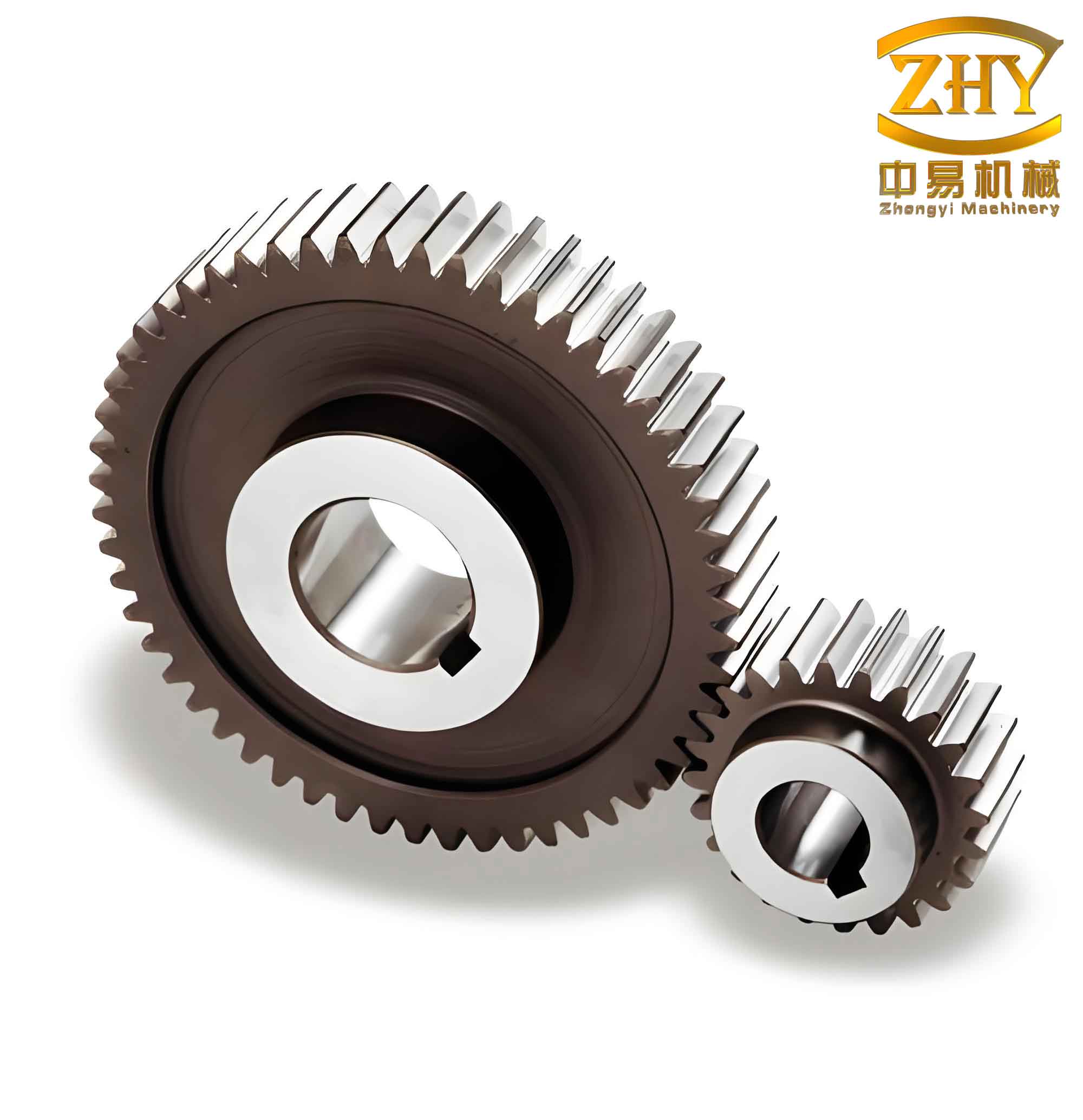
In summary, the methodology and formulas presented here offer a powerful tool for engineers engaged in the design and analysis of involute straight spur gears, enabling accurate prediction of the root fillet geometry and its influence on bending strength.