
The manufacturing of spur and pinion gears, which are fundamental components for power transmission and motion control, is a critical process in industries ranging from aerospace and defense to automotive and home appliances. Among various manufacturing techniques, cold precision forging has emerged as a highly advantageous method for producing spur and pinion gears. This process offers superior material utilization, high production rates, excellent mechanical properties, and good surface finish, all while maintaining the integrity of the metal grain flow. However, the complex geometry of a spur and pinion gear, characterized by its involute tooth profile, presents significant challenges. The most prominent issues are the difficulty in completely filling the sharp corners at the tooth tips and the exceptionally high forming loads required. These high loads directly compromise tooling life, making the economic production of high-precision spur and pinion gears a persistent technical hurdle. This article, from my perspective as a process engineer specializing in metal forming, presents a comprehensive numerical analysis and optimization study aimed at mitigating these challenges for a specific cylindrical spur and pinion gear. The goal is to develop robust process strategies that lower forming forces and ensure complete die fill.
To address the core challenges, three distinct cold forging process schemes were conceived for a standard spur and pinion gear with a module of 2.0, 30 teeth, a face width of 20mm, and a pressure angle of 20°. The performance of these schemes was rigorously evaluated using the finite element method (FEM). The first scheme, termed Plan A, represents the conventional closed-die forging approach with no specific feature to alleviate pressure or aid material flow. It serves as the baseline for comparison. The innovation lies in the two modified schemes. Plan B introduces a central “flash hole” or relief cavity in the upper die. Plan C incorporates “flow分流槽” or relief grooves at the tooth tip regions of the die. The primary objective of both Plan B and Plan C is to provide an escape path for excess material or to relieve hydrostatic pressure, thereby reducing the overall forming load. Crucially, these features were designed with practical manufacturability in mind, keeping their dimensions intentionally small—a 6mm diameter for the flash hole and a 0.5mm depth for the分流槽—to minimize subsequent machining while still achieving the desired effect.
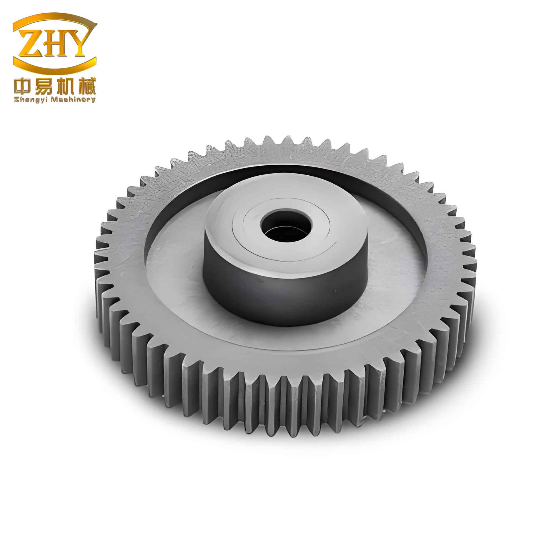
The foundation of any reliable process analysis is a accurate numerical model. For this study, a three-dimensional finite element model was constructed using Deform-3D software. Leveraging the axisymmetric nature of the spur and pinion gear, a quarter-symmetry model was employed to drastically reduce computational time without sacrificing result accuracy. The workpiece material was defined as AISI 4120 steel, a common alloy for gearing applications, modeled as a rigid-plastic body. The dies were treated as rigid bodies. The key simulation parameters are summarized in the table below:
| Simulation Parameter | Value / Setting |
|---|---|
| Workpiece Initial Dimensions | Ø50 mm × 38.5 mm (Billet) |
| Material | AISI 4120 Steel |
| Temperature (Workpiece & Die) | 20 °C (Room Temperature) |
| Friction Coefficient (Baseline) | 0.1 (Shear Model) |
| Upper Die Speed (Baseline) | 1 mm/s |
| Mesh Elements (Workpiece) | Approx. 100,000 (Tetrahedral) |
| Symmetry Condition | Quarter Model |
The finite element analysis provided clear and compelling results regarding forming load. The load-stroke curves for the three plans revealed a significant reduction in the maximum forging load for the modified schemes. Plan A, the conventional process, required a peak load of approximately 1,500 kN. In contrast, both Plan B (with flash hole) and Plan C (with分流槽) exhibited nearly identical peak loads of about 1,393 kN and 1,397 kN, respectively. This represents a force reduction exceeding 100 kN, or about 7%, despite the very small dimensions of the introduced features. This conclusively verifies that even minimally intrusive design modifications—a small flash hole or shallow分流槽—can have a profound effect on alleviating the forming pressure during the cold forging of a spur and pinion gear. The total forming load ($F_{total}$) in a closed-die forging operation can be conceptually broken down into components: the ideal deformation work ($F_{ideal}$), the force to overcome friction ($F_{friction}$), and the redundant work due to inhomogeneous deformation ($F_{redundant}$).
$$
F_{total} = F_{ideal} + F_{friction} + F_{redundant}
$$
The introduction of the flash hole or分流槽 primarily acts to reduce the $F_{redundant}$ component by relieving trapped material and mitigating excessive hydrostatic pressure, particularly in the challenging tooth-tip regions of the spur and pinion gear.
Beyond load reduction, the quality of the forged spur and pinion gear is paramount. This was assessed by examining the stress and strain distributions throughout the forming process. The evolution of the forming process showed a distinct pattern: the initial 50% of the stroke involved primarily upsetting of the billet with minimal localized stress. The subsequent stage was dedicated to tooth formation, where stress and strain values increased dramatically as material flowed into the complex die cavities. The maximum effective strain was consistently concentrated at the tooth tips, confirming that this area undergoes the most severe deformation and is most prone to under-filling. A comparison of the stress fields at the end of the forging stroke was particularly enlightening. While the stress was predominantly located in the tooth regions across all plans, the maximum stress value in Plan A reached approximately 5.5 (in normalized units). Plans B and C, however, successfully limited the maximum stress to around 3.0. More importantly, the stress distribution in Plans B and C was more uniform, indicating less severe stress concentrations. A more homogeneous stress state during formation typically translates to lower residual stresses in the final component, better dimensional stability, and potentially improved fatigue life for the spur and pinion gear. The superiority of Plans B and C in promoting a favorable stress state is a critical finding for ensuring the integrity of cold-forged spur and pinion gears.
While the geometric design of the die (flash hole vs.分流槽) is a major factor, the selection of process parameters is equally vital for optimizing the cold forging of spur and pinion gears. Two key parameters were investigated: the friction coefficient (µ) and the upper die speed (v). The friction coefficient is largely governed by the lubrication conditions at the die-workpiece interface. The die speed influences the strain rate, which affects material flow stress and machine dynamics. A full factorial design of experiments was simulated, combining three friction coefficients (0.1, 0.2, 0.3) with three die speeds (1, 5, 10 mm/s), resulting in nine distinct parameter sets. The primary output was the maximum forming load. The results are systematically presented in the following table:
| Parameter Set | Friction Coefficient (µ) | Upper Die Speed (v) [mm/s] | Max. Forming Load [kN] |
|---|---|---|---|
| a | 0.1 | 1 | 1,489 |
| b | 0.1 | 5 | 1,652 |
| c | 0.1 | 10 | 1,688 |
| d | 0.2 | 1 | 1,654 |
| e | 0.2 | 5 | 1,773 |
| f | 0.2 | 10 | 1,862 |
| g | 0.3 | 1 | 1,718 |
| h | 0.3 | 5 | 1,873 |
| i | 0.3 | 10 | 2,070 |
The analysis of the parameter study reveals clear and significant trends. The forming load for the spur and pinion gear is highly sensitive to both friction and speed. As expected, increasing either parameter leads to a higher required load. The lowest recorded load was 1,489 kN (Set ‘a’: µ=0.1, v=1 mm/s), while the highest soared to 2,070 kN (Set ‘i’: µ=0.3, v=10 mm/s). This constitutes a substantial difference of 581 kN, equivalent to a 28% increase. This range provides invaluable practical guidance. For instance, the results quantitatively demonstrate the critical importance of effective lubrication (low µ) in cold forging. The relationship between forming load ($F$), friction, and speed can be expressed through a simplified phenomenological model that incorporates the strain-rate sensitivity of the material:
$$
F \propto \bar{\sigma}_f \cdot (1 + \alpha \mu) \cdot \left(1 + \beta \ln\left(\frac{\dot{\epsilon}}{\dot{\epsilon}_0}\right)\right)
$$
where $\bar{\sigma}_f$ is the average flow stress, $\mu$ is the friction coefficient, $\dot{\epsilon}$ is the strain rate (correlated to die speed $v$), and $\alpha, \beta, \dot{\epsilon}_0$ are constants related to the process and material. This model explains the observed positive correlation. Based on the data, a practical parameter window for forging this specific spur and pinion gear would be a friction coefficient maintained at or below 0.2 (requiring high-quality lubricants) and a die speed kept at the lower end of the range (1-5 mm/s) to balance productivity with tool life. Selecting parameters from Set ‘d’ (µ=0.2, v=1 mm/s), yielding a load of 1,654 kN, represents a robust and feasible choice for production.
In conclusion, this numerical investigation successfully delineates effective pathways for optimizing the cold precision forging process of cylindrical spur and pinion gears. The introduction of strategically placed, small-scale geometric features in the forging die—specifically a central flash hole (Plan B) or tooth-tip分流槽 (Plan C)—proves to be highly effective. Both strategies achieved a marked reduction in the maximum forming load compared to the standard closed-die approach (Plan A), directly addressing the primary cause of premature die failure. Furthermore, these modified plans promoted a more uniform and lower stress state within the forged spur and pinion gear, which is indicative of superior product quality with minimized residual stresses and better microstructural integrity. The subsequent parameter sensitivity analysis quantified the profound impact of friction and die speed on forming load, establishing a clear operational window for selecting these variables in an actual production environment for spur and pinion gears. The combined strategy of intelligent die design (employing a分流槽 or flash hole) coupled with tight control over lubrication (low friction coefficient) and forming speed provides a comprehensive, theoretically-grounded framework for the economical and high-quality manufacturing of cold-forged spur and pinion gears.